Gas Clip Technologies GCT IR Link User manual

1 of 7
GASCLIPTECH.COM
Quick Reference Guide
GCT IR Link Software


GCT IR Link Software Quick Reference Guide
QRG-GCT-IRL-SW v3 Portable gas detectors you can count on 3 of 7
CONTENTS
Downloading and Installing GCT IR Link Software ....................................... 1
Quick Reference Icons ................................................................. 2
Download Logs . ........................................................................... . 2
Upgrade Firmware .......................................................................... 2
Calibration .................................................................................. 3
Hibernate ................................................................................... 3
Calibration Certicate ....................................................................... 3
Select Product .............................................................................. 3
Basic and Advanced Options ......................................................... 4-5
Settings and Options Unique to Specic Model Types . . . . . . . . . . . . . . . . . . . . . . . . . . . . . . . . . . . . 6
SGC ........................................................................................ 6
MGC Pump ................................................................................. 6
MGC Simple ................................................................................ 6
GCT IR Link Software Quick Reference Guide
QRG-GCT-IRL-SW v3 Portable gas detectors you can count on 1 of 7
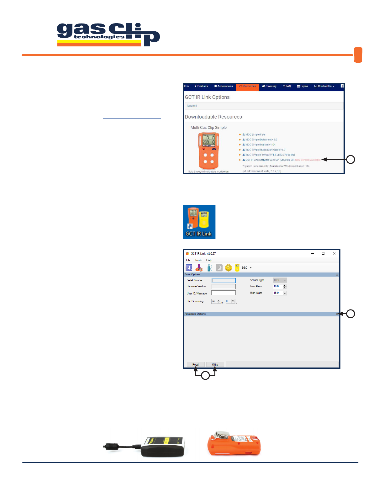
1. You will rst need to download and install the
most recent version of GCT IR Link Software (v2.0.55
or newer) from the Resources page on the Gas Clip
Technologies (GCT) website, www.gascliptech.com
[1a]. If you have trouble downloading or installing the
software, please contact GCT Service Department.
2. Once installed, open the program by clicking on the
GCT IR Link Software icon that appears on your desktop.
Once the program is open, you will notice a row
of icons at the top for quick access to the most
commonly used tools and two main sections, Basic
Options and Advanced Options. If the Advanced
Options are not displayed, you can reveal them by
clicking the down arrows [2a] on the right side of the
program screen. To hide them you would click the
up arrows in the same location. The most important
buttons to understand in this program are the “Read”
& “Write” buttons [2b]. When clicked, “Read” will pull
the information and settings that are currently on
the detector and display them in the corresponding
settings boxes within the program screen.“Write”, on
the other hand, will take any new settings or changes
that you make and apply them to the detector being
communicated with via the GCT IR Link.
DOWNLOADING AND INSTALLING GCT IR LINK SOFTWARE
To communicate with a detector via the GCT IR Link you will need to place the detector face down in front of the GCT IR Link
with the IR communication windows facing each other about 1-2 inches apart (pictured below). Note: your detector will need
to be powered on and the IR communications window free from dirt or debris to ensure successful IR communication.
2b
2a
1a
GCT IR Link Software Quick Reference Guide
QRG-GCT-IRL-SW v3 Portable gas detectors you can count on 2 of 7
QUICK REFERENCE ICONS
1. Download Logs: Here you can use your GCT IR
Link to download the event logs or data logs from your
detector. For more information on what data is contained in
each type of log, or instructions on how to interpret the logs,
please contact GCT Service department. To download logs,
select a location to save the logs to [1a]. For easy retrieval,
it is recommended to either use your PC’s desktop or a
dedicated folder as the destination. Check the “Open File
After Download” box [1b] if you would like the log to open
immediately after download is complete. Next, click the
drop-down arrow [1c] and select the log type that you wish to
download. Click“Download” [1d] to begin compiling the log.
2. Upgrade Firmware: Here you can upgrade the
rmware on your detector. To upgrade your rmware,
download the most recent version of the rmware for your
detector from the Resources page on our website. Once the
rmware download is complete, place your detector face down
in front of the GCT IR Link with the IR communication windows
facing each other [2a]. Next, either drag the downloaded
rmware le into the Upgrade Image File box [2b] or click
“Browse” to nd the downloaded le on your computer to
select. To complete the upgrade, click “Upgrade”[2c]. Once
the rmware update is complete, the status bar will display
“Successful” in green and the detector will power cycle to apply
the update. If you have any issues updating the rmware on a
detector, please contact GCT Service department.
1
2b
1d
2c
2 3 4 5 6
Item Description
1 Download Logs
2 Upgrade Firmware
3 Calibration
4 Hibernate (SGC Plus Only)
5 Calibration Certicate
6 Select Product
1a
1b
1c
2a

GCT IR Link Software Quick Reference Guide
QRG-GCT-IRL-SW v3 Portable gas detectors you can count on 3 of 7
3. Calibration:
Here you can calibrate both Multigas and Single Gas
detectors. Note: although you can calibrate all detectors through the GCT IR
Link Software, a much more user-friendly Manual Calibration mode is built into all
Multigas detector menus (see your detector’s User’s Manual for manual calibration
instructions). To perform a calibration through the GCT IR Link software, you
will need the following: your detector, the calibration cap that came with the
detector, a bottle of calibration gas, a regulator and tubing (hose). First, set the
gas concentrations [3a] to match the mixture in the bottle that you are using for
the calibration. Connect the regulator to the bottle of gas. Attach the calibration
cap to the detector and connect the tubing (hose) from the calibration cap to
the regulator. Once all is set up, click “Calibrate”[3b]. The program will prompt
you to apply the calibration gas and then notify you of a successful calibration or
failure in the status bar. If you have further questions on performing a calibration
through the GCT IR Link Software, please contact the GCT Service department.
6. Select Product: Here you can select the product that you wish to
see the Settings and Options for. When a detector is Read with the GCT
IR Link Software it will automatically direct you to the correct product tab.
3a 3b
5a
5b
5d
5. Calibration Certicate: Here you can print a Calibration
Certicate for a successful calibration completed within the last 48
hours. To generate the Calibration Certicate, enter the Gas Lot Number
[5a] from the gas bottle used to complete the calibration, the name of the
individual preparing the certicate [5b], and the company information [5c]
to be displayed on the certicate. Once this information has been entered
select a destination folder [5d] for the certicate to be saved and click
“Generate Certicate”.
4. Hibernate: Hibernation mode is only available on the SGC Plus family of detectors (SGC-P-H and SGC-P-C). This will
power down the detector for storage and no life remaining will be removed during hibernation. Note: Hibernating an
SGC-Plus will clear the logs so, if you require a copy of the logs for documentation, please download them before attempting
to hibernate.
5c

GCT IR Link Software Quick Reference Guide
QRG-GCT-IRL-SW v3 Portable gas detectors you can count on 4 of 7
BASIC AND ADVANCED OPTIONS
Most of the editable settings for Gas Clip Technologies detectors are similar across all Multigas product lines, however there
are some Settings and Options that are unique to specic model types. The following section will be an overview of settings
that are shared between model types.
Serial Number:
Once the detector has been “Read” it will populate the Serial Number of the detector in this box.
Firmware Version:
Once the detector has been “Read” it will populate the current Firmware Version installed on the detector
in this box.
User ID/Message:
An optional, user-programmable, text message containing up to 46 alpha-numeric characters can be used
to show company branding, a detector identier, or any other pertinent information. Default User ID/Message is "GAS CLIP
TECHNOLOGIES". Note: The SGC family of detectors is limited to 6 characters.
Most of the following settings and options are only available on Multigas detectors. Options that are also available on
SGC and SGC Plus will be marked with an *
Low Alarm:
Used to set the Low Alarm threshold for each gas. *
High Alarm:
Used to set the High Alarm threshold for each gas. *
STEL Alarm:
Used to set the Short-Term Exposure Limit Alarm threshold for H2S and CO.
TWA Alarm:
Used to set the Time Weighted Average Alarm threshold for H2S and CO.
Language:
The detector can display all its text prompts in any of six languages: English, German, French, Spanish, Italian or
Portuguese. Note:“OL”, “ERROR” and sensor icons (H2S, CO, O2& LEL) remain the same for all languages.
TWA Method:
The algorithm used to calculate the TWA (Time Weighted Average) can be set to either an average over a
moving window (OSHA) or as a cumulative average (ACGIH).

GCT IR Link Software Quick Reference Guide
QRG-GCT-IRL-SW v3 Portable gas detectors you can count on 5 of 7
TWA Interval:
The TWA Interval denes the time frame over which the long-term average is calculated. Default is 8 hours.
STEL Interval:
The STEL Interval denes the time frame over which the short-term average is calculated. Default is 15 minutes.
50% LEL =:
Used to change the % by volume of CH4 that is determined to be equal to 50% LEL (typically 2.5% in N. America
and 2.2% in EU).
Calibration Interval:
The Calibration Interval controls how often the detector noties the user to calibrate the sensors. The
interval can be individually adjusted for each sensor. *
Bump Interval:
The Bump Interval controls how often the detector noties the user to bump test the sensors. The interval can
be individually adjusted for each sensor. *
Calibration Gas:
When the detector is calibrated, it scales the sensor readings to match the concentrations of the applied
gases. The calibration gas concentrations can be adjusted to match the respective levels contained within the gas bottle.
Default is 25ppm H2S, 100ppm CO, 18% O2and 50% LEL (2.5% vol CH4). *
Sensor Enabled:
Individual sensors can be disabled. A disabled sensor is completely removed from the detector’s display
for sensor readings, alarm limits and calibrations. Caution: A disabled sensor will not measure gas or detect alarm
conditions.
SAFE Display:
If Safe Display is enabled, screen will display “SAFE” as long as there are no gas or detector alerts.
Self-Test Lock:
If a sensor fails a self-test, the detector shows“Err”on the display and goes into high alarm. By default, the
alarm can be silenced by pressing the Power/Menu Button. The Self-Test Lock option prevents the alarm from being silenced.
Auto Zero:
This option automatically zeros the sensors every time the detector is activated (this is enabled by default and it is
recommended that it remains enabled).
O Lock:
This option prevents the user from deactivating the detector's sensors with the Power/Menu Button.
Maintenance Notication: If Maintenance Notication is enabled, the detector will periodically ash the maintenance LED
when a bump test or calibration is due. Otherwise, if the option is disabled, the detector will only show the maintenance text
on the display.
Dock Lock:
This option restricts bump tests and calibrations to only being able to be performed with one of Gas Clip
Technologies’Clip Docks. Manual tests will not be able to be performed.
Latching Alarms:
Alarms are non-latching by default, therefore, once the gas readings fall back within the set limits after an
alarm condition, the detector will cease to alarm and return to normal operation. Latching alarms will hold the detector and
its display in its peak alarm condition until the Power/Menu Button is pressed.
LEL by Volume CH4:
Allows the detector to display gas readings as %-by-volume CH4 rather than % LEL.
Activity LED Period:
This option allows the detector to ash a single LED at a specied interval to indicate that the detector is
on. The interval between ashes can be set anywhere from 5 seconds to 120 seconds. To disable this function, type "0" in the
Activity LED Period box and press ENTER. The box will display "OFF".

GCT IR Link Software Quick Reference Guide
QRG-GCT-IRL-SW v3 Portable gas detectors you can count on 6 of 7
This section will cover the settings and options that are unique to specic model types.
Life Remaining [1]:
Displays the total life remaining of the detector in months and days.
Display [2]:
Lets the user select how the detector display is congured. The display can be set to show Sensor Reading at
all times, Life Remaining at all times, or Sensor/Life Remaining. The default, Sensor/Life Remaining, setting will show Life
Remaining until there is a reading of the target gas and it will then switch over to the Sensor Reading display, once the reading
reaches “0” again it will switch back to Life Remaining.
Hide Bump Due LED ashing [3]:
Lets the user select whether to enable, or disable, the Flashing LED notication that a Bump
is due (Similar to the Maintenance Notication for Multigas detectors).
Self-Test Interval [4]:
Sets the interval for the detector to request a self-test.
MGC PUMP
Pump Test:
Requires the pump inlet to be blocked and unblocked on detector start up as well as after a Pump Block alarm has
been acknowledged.
MGC SIMPLE
Life Remaining:
Displays the total life remaining of the detector in months and days.
Life Display:
While the detector is not in alarm, the display screen will show the Life Remaining instead of the Sensor Readings.
* For the most up to date list of Options and Settings please refer to your product’s User’s Manual. *
1
2
3
4
SGC & SGC PLUS

GCT IR Link Software Quick Reference Guide
QRG-GCT-IRL-SW v3 Portable gas detectors you can count on 7 of 7
Gas Clip Technologies, Inc.
305 W FM 1382 Ste 540
Cedar Hill, TX 75104 USA
Toll Free: 1 (877) 525-0808
Phone: +1 (972) 775-7577
Fax: +1 (972) 775-2483
E-mail: [email protected]om
Website: www.gascliptech.com
CONTACT INFORMATION
Table of contents
Popular Conference System manuals by other brands


Bosch
Bosch DCN Next Generation Installation and operation manual

TracPhone
TracPhone v7ip installation guide

Rath
Rath Janus SmartView Visual Installation & operation manual

Studer
Studer Xcom-GSM quick guide

Cisco
Cisco 7935 - IP Conference Station VoIP Phone Administration guide

Shure
Shure FC 6021 datasheet