Gas Clip Technologies Clip Dock User manual


MGC Dock User’s Manual
V1.5 Port able gas det ect or s you can count on. 2 of 15
Contents
Warnings Statements/Avertisseement ..........................................................................................3
READ FI RST BEFORE OPERATI ON ... ... .. .. .. .... .. .... .. ... .. .. .. ... .. .. .. .... .. .... .. ... .. .. .. ... .. .. .. .... .. 3
Description ...............................................................................................................................................4
Basic Operation.......................................................................................................................................5
Clip Dock Com ponent s ... .. .. .... .. .. .. .. .. .... .. .. .. .. .. .... .. .. .. .. .. .... .. .. .. .. .. .... .. .. .. .... .. .. .. .. .. .... .. 5
LEDs......................................................................................................................5
User Operation........................................................................................................................................6
Turning t he Clip Dock On and Off . .... .... .. .... .. .... .. .... .... .. .... .... .. .... .. .... .. ... .. .. .. ... .. .. .. .... . 6
Charging . .... .. .... .. .... .. .... .... .. ... .. .. .. .... .. .... .. .... .... .. .... .... .. .... .. .... .. .... .... .. .... .... .. .... .. .... 6
Calibr ation Gas I nst allat ion .. .. .. .. .. .... .. .. .. .. .. .... .. .. .. .... .. .. .. .. .. .... .. .. .. .. .. .... .. .. .. .. .. .... .. .. .. . 6
Bu tt on Usage . .. .. .. .... .. .... .... .. .... .. ... .. .. .. .... .. .... .... .. .... .. .... .... .. .... .. .... .. .... .... .. .... .... .. .... 6
Troubleshoot ing Failures ... .. .. .. .. .. .. .. .. .... .. .. .. .. .. .... .. .. .. .. .. .... .. .. .. .. .... .. .. .. .. .... .. .. .. .. .. .... . 7
Clip Dock Configuration.......................................................................................................................8
Clip Dock Opt ions . .. .... .... .. .... .. .... .. .... .... .... .. .... .. .... .. .... .... .. .... .... .. .... .. .... .. .... .... .. ... .. .. 8
Detector Opt ions . .. .... .. .... .. .... .... .. .... .. ... .. .. .. .... .... .. .... .. .... .. ... .. .. .. .... .. ... .. .. .. .... .. .... .... . 8
Clip Dock Records (Logs).....................................................................................................................9
Clip Dock Log Form at ... .. .. .... .. .. .. .. .. .... .. .. .. .... .. .. .. .. .. .... .. .. .. .. .. .... .. .. .. .. .... .. .. .. .. .. .... .. .. .. 9
Logged SGC Opt ions .. .. .. .. .. .. .. .. .. .. .... .. .. .. .. .... .. .. .. .. .... .. .. .. .. .. .... .. .. .. .. .... .. .. .. .. .. .... .. .. .. .. 9
Logged MGC Opt ions ............................................................................................. 10
Wall-Mounted Clip Dock ................................................................................................................... 11
I nstallat ion Procedur e: ........................................................................................... 11
Clip Dock Specifications.................................................................................................................... 13
Contact Information ........................................................................................................................... 14
Limited Warranty................................................................................................................................ 15

MGC Dock User’s Manual
V1.5 Port able gas det ect or s y ou can count on. 3 of 15
Warnings Statements/Avertisseement
The Clip Dock may not support all gases. For a complete list, please contact GCT.
Do not use the Clip Dock if it appears to be damaged. Inspect it before each use.
Ensure the Clip Dock is used with certified calibration gas.
DO NOT use expired calibration gas. Please check the expiration date located on the bottle.
DO NOT operate the Clip Dock in a hazardous environment
Do not expose the Clip Dock to electrical or mechanical shocks before, during, or after use.
Do not allow liquids to condense and/or use high power sprays on the Clip Dock.
Gas Clip Technologies recommends periodic back up of the data stored on the USB Memory.
The Clip Dock contains a lithium battery that must be disposed of by a qualified recycler. Check local
regulations for proper disposal.
Warning: The battery may present a fire or chemical burn hazard if mistreated. Do not disassemble, heat
above 100°C (212°F), or incinerate. Contact Gas Clip Technologies for replacement instructions. Use of
another battery may present a risk of fire or explosion.
DO NOT charge the instrument in temperatures above or below the specified range of 0°C to 40°C.
Read the entire Clip Dock manual and follow all instructions to ensure proper use and safe installation.
READ FIRST BEFORE OPERATION
Gas Clip Technologies ( GCT) Clip Docks are designed t o ensure t hat the port able gas
det ect or s ar e able t o det ect and alar m t o k now n t ar get gas concen t rat ion s. Dat a f rom t hese
t ests is st ored t o t he onboard USB m em ory which can be downloaded for analysis at a lat er
tim e. I t is y our responsibilit y to pr operly use the Clip Dock.

MGC Dock User’s Manual
V1.5 Port able gas det ect or s y ou can count on. 4 of 15
Description
The Gas Clip Technologies Clip Dock is an all-in- one stan d- alone docking st at ion designed
for m axim um test ing efficiency and port abilit y. I t test s up t o four unit s sim ult aneously,
reducing the testing time and gas usage. With only two buttons, it’s simple to train workers
how t o use it for r egular bum p t est s, occasional calibrat ion s, or t o deactiv ate det ect ors. I t
can be opt ionally housed in a r ugged Pelican © case or a wall- m ou nt able m et al enclosur e.
Logs are st or ed on a USB flash drive which can easily be t ransferr ed t o a com put er for
analysis.
Each Clip Dock com es wit h t he following st andard featur es:
Test 4 unit s at one tim e, up t o 12 instrum ent s in a m inut e
Easy 1 but ton operation
Robust r echar geable int ernal bat t ery , up t o 15 00 t est s before r echarging
I nternal gas cylinder regulator and pr essure gauge
USB flash m em ory for bum p t est and event log storage
Opt ional unit configu rat ion and firm w are updat es via GCT Manager Soft w are
Rugged Pelican© case or Wall- m ount able case
No com put er required t o operat e

MGC Dock User’s Manual
V1.5 Port able gas det ect or s y ou can count on. 5 of 15
Basic Operation
Clip Dock Components
1
2
3
6
8
9
10
4
5
11
7
LEDs
LED
Color
Description
Unit LEDs
orange
test in progress
red
test failed
green
test passed
orange cycling
charging
Power LED
green
pow er ed on
green blinking
low bat tery
orange
test in progress
orange blinking
No USB m em ory det ect ed*
* The Clip Dock will be unable t o record t est result s if USB m em ory is not inst alled
Entry
Description
1
Det ect or Bay
2
Access Hat ch Screw s ( x 2)
3
Pressure Gauge
4
Gas Bot t le
5
USB Mem ory St ick
6
Unit LED ( x4)
7
Power LED
8
But t ons
9
Charging Port
10
Exhaust Port
11
Solenoid, Regulat or , Gauge
12
( Opt ional) Gas I n let

MGC Dock User’s Manual
V1.5 Port able gas det ect or s y ou can count on. 6 of 15
User Operation
Turning the Clip Dock On and Off
The Clip Dock is pow ered by an int ernal rechargeable bat t ery t hat can perform up t o 1500
bum p t est s. Pressing either but ton w ill aut om atically wake up t he Clip Dock and perform the
button’s associate actions. The Clip Dock w ill aut om at ically t urn it self off bet ween t est s,
unless the charger is connect ed.
Charging
Connect the supplied DC pow er adapt er to t he Charging Port on the Clip Dock t o charge the
int ernal batt ery. The Unit LEDs will cycle unt il the batt ery is fully charged. A com plet e
charge takes approx im at ely 3 hours and last s for approxim at ely 1500 bum p t est cycles.
DO NOT charge the instrument in temperatures above or below the specified range of 0°C to 40°C
DO NOT substitute any other battery type than specified and supplied by Gas Clip Technologies.
Calibration Gas Installation
The Clip Dock requires a calibrat ion gas bot tle t o be installed in order t o perform t est s on
t he det ect ors. To install, rem ove t he Access Hatch Screws ( x2) and lift th e access pan el.
Thread the bot t le int o the CG- 10 fit ting until tight . Once properly connected, t he gas gauge
will indicate t he bott le pressur e.
By default , t he Clip Dock assum es t hat t he bot t le cont ains four gases so t hat any det ect or
m odel can be t est ed. The GCT Manager soft w are allows y ou t o specify t he gas
concent rat ions. The default concent rat ion is set for a m ix of all gas t ypes:
H2S: 25 ppm CO: 100 ppm O2: 18% LEL: 50%
Button Usage
Operat ion of t h e Clip Dock is det er m ined by t h e t wo but t ons on t he t op plat e:
Bump Test: Br iefly applies gas t o ensure t hat t he det ect or s r espon d
Calibration: Calibrates the detectors’ measurement accuracy against t he applied gas
Both (hold): Turns off or hibernat es t he det ect or s
Place up t o four act ivat ed det ect ors int o t he det ect or bay s. The Clip Dock can t est up t o four
det ect ors sim ult aneously. Ensure t hat the gas bot t le m at ches t he gas types required by the
insert ed det ect or s. The Clip Dock can t est w it h different det ect or s at t he sam e t im e if u sing
a m ult i- gas blend calibrat ion m ix.
To begin the test , pr ess the Bump Test and/ or the Calibration but ton. A bum p t est will t ake
approxim at ely 20 seconds; a calibrat ion 90 seconds; hibernation a few seconds. While t he
test is active, the LEDs will t urn ORANGE. When t he t est has com plet ed, t he LEDs will turn
GREEN for pass or RED for fail. Wait until the power but ton shows the overall result ( GREEN
or RED) befor e r em oving t he det ect or s.
Ev ery t est will perform t he follow ing m aint enance oper at ions:
Upgrade each detector’s firmware (if required)
Set the detector’s date and time (if supported)
Test each detector’s beeper
Configure each detector’s user options (as required)

MGC Dock User’s Manual
V1.5 Port able gas det ect or s y ou can count on. 7 of 15
Download each detector’s logs
Bum p, Calibrat e, or hibernat e as r equest ed
Record t he t est t o t he USB m em ory
Troubleshooting Failures
1. I nspect t he det ect or sensor an d beeper cavit ies an d clear any obst ruct ions.
2. Clean t he sm all I R com m unication window located on t he top of t he det ect or.
3. Verify the gas bot tle is not em pt y. 58L bottles are “full” at 500 PSI; 116L at 1000
PSI .
4. Try relocating t he Clip Dock away fr om bright light sour ces, which m ay int erfere w it h
I R com m un icat ion bet ween t he Clip Dock and t he det ect ors.
5. I f a m onit or has failed 3 aft er t hr ee t est att em pt s, please cont act Gas Clip
Technologies.
MGC Dock User’s Manual
V1.5 Port able gas det ect or s y ou can count on. 8 of 15
Clip Dock Configuration
The Clip Dock is configured wit h t he GCT Manager software. The lat est version is available
on t he GCT website at www.gascliptech.com , along with its User’s Manual.
The GCT Manager soft w are can com m un icat e w it h t he Clip Dock t hr ough I R or USB as
select ed by t he radio but t ons. I R com m unication is handled t hrough Bay 1 of t he Clip Dock
and if t he I R Link is placed int o Bay 1. For I R com m unicat ion, conn ect t he Clip Dock t o a
char ger and place t he GCT I R Link int o Bay 1. Dir ect USB oper at ion wit h t he m em ory st ick
conn ect ed t o t he PC offers fast er t r an sfers or configurat ion w it hout a GCT I R Link .
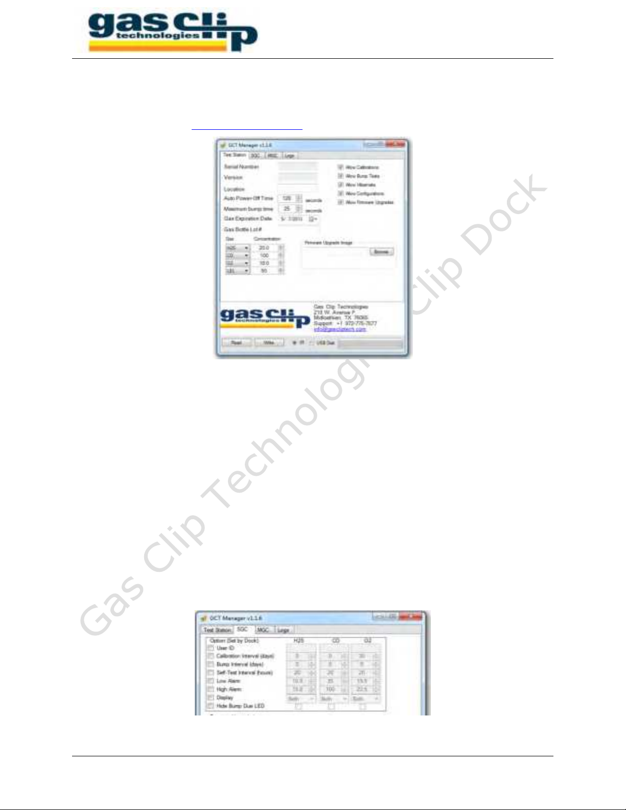
Clip Dock Options
The softwar e pr ogram will provide a det ailed descript ion of each opt ion if t he m ouse is
hovered of it . The Location, Gas Expiration Date and Gas Bottle Lot # are opt ional
par am et er s t hat will be recorded int o t he log file wit h each t est. The ch eckbox es can enable
or disable various featur es of t he Clip Dock, including: calibrat ions, bum p t ests,
hibern at ions, det ect or configurat ion and det ect or firm w ar e upgr ades.
Detector Options
Ev ery det ector t est ed by the Clip Dock can opt ionally be program m ed wit h various
configurat ion set tings. By default , the Clip Dock will not reconfigure any detectors. The GCT
Manager soft w are allow s fine- gr ained cont r ol ov er w hich opt ion s ar e pr ogram m ed int o t he
det ect or s and what t hose set t ings w ill be.

MGC Dock User’s Manual
V1.5 Port able gas det ect or s y ou can count on. 9 of 15
Clip Dock Records (Logs)
The Clip Dock records t he result s of each t est t o it s USB m em ory . I n addit ion, it will
download each detector’s event log. Clip Dock log files are stored in Comma Separated
Value ( CSV) form at which can easily be parsed by a spreadsheet program for viewing and
m anipulation.
Clip Dock Log Format
The first lines of t he log file provide a header for the log dat a. Each t est is st ored in m ultiple
lines:
Line 1: Overall Clip Dock t est result s
Dat e and Tim e of t est
Test t ype ( Bu m p Test , Calibr at ion or Turn Off)
Clip Dock Serial Num ber
Overall pass/ fail test result
Firm ware and Hardware versions
Locat ion ( opt ional user st r ing t hat can be configur ed w it h t he GCT Man ager )
Line 2: Bay t est result s for t he insert ed det ect or
Bay Num b er ( 1 - 4)
Detector Model
Detector serial num ber
Detector pass/ fail result
Detector firm ware and hardwar e versions
Beeper pass/ fail result
Det ect or opt ion s ( var ies by det ect or t ype)
Line 3: Det ect or sensor( s) t est r esult s
Sensor Type
Sensor pass/ fail result
Sensor reading
Gas bot t le details
Sensor opt ions ( v ar ies by det ect or t y pe)
Logged SGC Options
The SGC Dock logs t he following Single Gas Clip ( SGC) det ect or opt ions on Lin e 2 :
Show Sensor Readings ( T/ F)
Bu m p Flash Disabled ( T/ F)
Hide Clock ( T/ F)
User I D
Self- Test I nt er val
The following SGC Sensor opt ions are logged on Line 3:
High and Low alarm s
Calibrat ion and Bum p Test I nt erv als
Calibrat ion and Bum p Due ( day s)

MGC Dock User’s Manual
V1.5 Port able gas det ect or s y ou can count on. 10 of 15
Logged MGC Options
The MGC Dock logs t he following Multi Gas Clip (MGC) detector opt ions on Line 2:
User Message
Language
TWA m ethod
TWA and STEL intervals
SAFE m ode ( T/ F)
Self- Test Lock ( T/ F)
Au t o- Zer o ( T/ F)
Maint enance Not ificat ion ( T/ F)
Dock Lock ( T/ F)
Lat ching Alar m s ( T/ F)
The following MGC Sensor opt ions are logged on Line 3:
Sensor enabled/ disabled
Low, High, STEL and TWA alarm s
Last calibration and calibrat ion int erval
Last bum p t est and bum p t est int erval

MGC Dock User’s Manual
V1.5 Port able gas det ect or s y ou can count on. 11 of 15
Wall-Mounted Clip Dock
The w all- m ou nt ed Clip Dock exchan ges t h e port able
Pelican© case for an enclosure suit able for
perm anent , fixed installat ions. All ot her feat ur es
and operat ions are the sam e.
The Clip Dock is m ount ed wit h four screws
( supplied) . For inst allat ion on dry wall, t he pr ovided
drywall anchors should be used. For installat ion on
brick or m etal structures, the user w ill have t o
supply suit able m ount ing hardwar e. A conv enient
wall- m ounting t em plat e is included to help locat e
t he m ount ing screws.
IMPORTANT: Select a location near a power source that is required for charging of the
internal battery.
Installation Procedure:
I n m ost cases t he Clip Dock can be inst alled wit h t he use of t he following t ools:
# 2 Philips screw driver
Level
Clip Dock Mount ing Tem plate
1. Using t he provided installat ion t em plat e and a level, m ark out t he four screw
locations

MGC Dock User’s Manual
V1.5 Port able gas det ect or s y ou can count on. 12 of 15
2. Screw the dry wall anchors int o t he m ark ed locations.
3. Screw in t he top t wo screws m ost of t he way. Leave enough space
for t he Clip Dock case to slide over t he screw.
4. Hang the Clip Dock on t he top t w o screws.
5. Open t he gas cylinder com part m ent and scr ew in the rem aining
two screws
6. To com plete t he installation:
Lead the exhaust t ube away t o a suit ably vent ed location.
I nstall t he gas cy linder or conn ect t he ext ernal gas sour ce.
Connect t he DC pow er source t o t he Clip Dock .
Secure t he gas cy linder com part m ent lid wit h t he access hat ch screws.

MGC Dock User’s Manual
V1.5 Port able gas det ect or s y ou can count on. 13 of 15
Clip Dock Specifications
Portable Clip Dock
Wall-Mounted Clip Dock
Size
19.78 x 15.77 x 7.41 in.
(50.2 x 40 x 18.8 cm )
17.75 x 12 x 6.5 in.
(45.2 x 30.5 x 16.5 cm )
Weight
(wit hout gas cylinder)
15 lbs. (6.8 kg.)
14lbs. (6.4 k g.)
Operating Temperature
41 t o + 104˚F (5 t o + 40˚C)
Battery Life
15 00 Bu m p Test s
Charge Time
2- 3 hours
LEDs
5 red/ green/ or ange LEDs ( 1 for each unit, 1 for power)
Display
Alphanum eric Liquid Crystal Display ( LCD)
Log Capacity
Approxim ately 5 m illion t ests (2GB, r em ovable USB m em ory)
Warranty
Full 2 year s
User Options
Locat ion, Gas ex pirat ion dat e, Gas bot tle lot num ber, gas concent rat ions,
bum p gas t im e, bum p sensor pass crit er ia, calibr at ions, bum p t ests,
hibernat ions, det ect or configur at ion, firm w are upgr ades, t urn off t im e
Note: This equipment has been tested and found to comply with the limits for a Class B digital device, pursuant to Part 15 of
the FCC Rules. These limits are designed to provide reasonable protection against harmful interference when the equipment is
operated in a commercial environment. This equipment generates, uses, and can radiate radio frequency energy and, if not installed
and used in accordance with the instruction manual, may cause harmful interference to radio communications.

MGC Dock User’s Manual
V1.5 Port able gas det ect or s y ou can count on. 14 of 15
Contact Information
Gas Clip Technologies, Inc.
610 Uptown Blvd, Suite 4100
Cedar Hill, TX 75104
Toll Free: (877) 525-0808
Phone: (972) 775-7577
Fax: (972) 775-2483
E-mail: [email protected]
Website: www.gascliptech.com

MGC Dock User’s Manual
V1.5 Port able gas det ect or s y ou can count on. 15 of 15
Limited Warranty
Gas Clip Technologies (“GCT”) warrants this product to be free from defects in material and
workmanship under normal use and service for a period of two years beginning upon the date of
purchase. This warranty extends only to the sale of new and unused products to the original
buyer. GCT’s warranty obligation is limited, at GCT’s option, to refund of the purchase price,
repair, or replacement of a defective product that is returned to a GCT authorized service center
within the warranty period. In no event shall GCT’s liability hereunder exceed the purchase price
actually paid by the buyer for the product. This Warranty does not include: (1) Routine
replacement of parts due to the normal wear and tear of the product arising from use. (2) Any
product which in GCT’s opinion has been misused, altered, neglected or damaged by accident
or abnormal conditions of operation, handling, or use. (3) Any damage or defects attributable to
repair of the product by any person other than the authorized dealer, or installation of
unapproved parts or gas cylinders on or in the product. The obligations set forth in this warranty
are conditional on: (1) Proper storage, installation, use, maintenance, and compliance with the
user’s manual instructions and any other applicable recommendations of GCT. (2) The buyer
promptly notifying GCT of any defect and, if required, promptly making the product available for
correction. No goods shall be returned to GCT until receipt by the buyer of instructions from
GCT. (3) The right of GCT to require that the buyer provide proof of purchase such as the
original invoice, bill of sale or packing slip to establish that the product is within the warranty
period. The buyer agrees that this warranty is the buyer’s sole and exclusive remedy and is in
lieu of all other warranties, express or implied, including but not limited to any implied warranty
or merchantability or fitness for a particular purpose. GCT shall not be liable for any special,
indirect, incidental, or consequential damages or losses, including loss of data, whether arising
from breach of warranty or based on contract, tort, or reliance on any other theory. Some
countries or states do not allow limitation of the term of an applied warranty, or exclusion or
limitation of incidental or consequential damages, the limitations and exclusions of this warranty
may not apply to every buyer. If a court of competent jurisdiction holds any provision of this
warranty invalid or unenforceable, such holding will not affect the validity or enforceability of any
other provision.
Table of contents
Other Gas Clip Technologies Measuring Instrument manuals


Popular Measuring Instrument manuals by other brands

Unifire
Unifire FORCE 50 Maintenance instructions

Micromeritics
Micromeritics TriStar II 3020 Maintenance instructions

DEHACO
DEHACO VAC CLOUD user manual
 user manual")
Carrier
Carrier Indoor Air Quality (IAQ) user manual

Martin Lishman
Martin Lishman Field Check PLUS Instruction manual and users guide

VorTek
VorTek MT160 instruction manual

Tektronix
Tektronix WCA2UP-03 instructions

ST
ST DELTA 1000/400A AC DC user manual

TE Connectivity
TE Connectivity M242-05 Series installation instructions

Fluke
Fluke 1736 Manual supplement

Spectrasensors
Spectrasensors SS2100 Hardware installation and maintenance manual

DEHN + SÖHNE
DEHN + SÖHNE DEHNrecord DRC SCM XT operating manual


