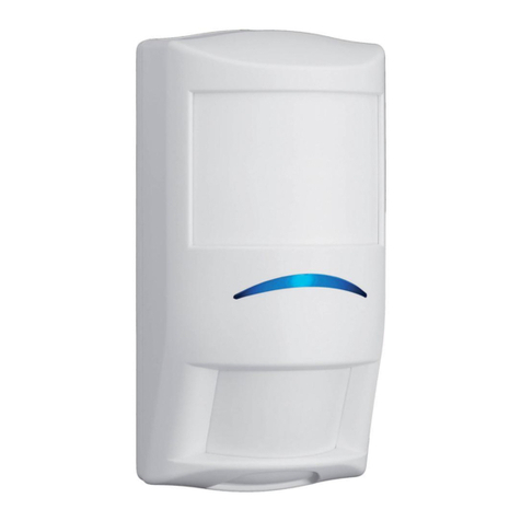
GASSONIC GASSSONIC MM0100 User manual

InstallatIon and User GUIde for
GasssonIC MM0100 /eH6028
UltrasonIC Gas leak deteCtors
teCHnICal doCUMentatIon
t


InstallatIon and User GUIde for
GasssonIC MM0100 /eH6028
UltrasonIC Gas leak deteCtors
From serial number: 056-001
Gassonic MM0100 / EH6028

Index
Page:
1. Introduction ................................................................................................................................... 4
2. Description of Gassonic MM0100 / EH6028 ............................................................................... 4
3. Installing the Detector
3.1. Area Monitored by Gassonic MM0100 / EH6028 ...................................................... 4
3.2. Environmental Conditions ........................................................................................... 5
3.3. Mounting the Detector ............................................................................................... 5
3.4. Cable Connections ..................................................................................................6-7
4. Power Requirements ...................................................................................................................... 8
5. Adjustments
5.1. Adjustable Alarm Level Settings .................................................................................. 8
5.2. Alarm Delay & Cut-on Frequency Settings
5.2.1. Gassonic EH6028 .......................................................................................... 9
5.2.2. Gassonic MM0100 ......................................................................................... 9
5.2.2.1 Alarm Delay..................................................................................................... 9
5.2.2.2 Cut-on Frequency ........................................................................................... 9
6. Operating the Equipment
6.1. Trip Output Data ......................................................................................................... 10

safetY ConsIderatIons
WARNINGS
• Switchoffallequipmentbeforeconnectingordisconnectingthem.Failuretodosocould
damage the equipment.
• TheGasLeakDetectorsGassonic MM0100 / EH6028 areintrinsicallysafeunits
(EEx ib IIC T6). The voltage and current levels at the detector must be limited by Ex approved
isolators/barriers. Failure to do so may result in an explosion.
• Precautionsshallbetakentoavoidelectrostaticchargingofthedivice.
• OnlyoriginalGassonicscrewswithisolatorsshouldbeusedtotightenthelid.
aBoUt tHIs InstallatIon GUIde
ThisinstallationguidedescribeshowtoinstalltheGassonicMM0100/EH6028GasLeakDetector
andtellsyouhowtoadjustittothelocalconditions.
Copyright @ 2004 Gassonic
Allrightsreserved.Nopartofthispublicationmaybereproducedordistributedinanyform,orbyanymeans,
withoutpriorconsentinwritingfromGassonic,Ballerup,Denmark.

InstallationandUserGuideforUltrasonicGasLeakDetectors Page 4
1. IntrodUCtIon
ThisinstallationguidedescribeshowtoinstallUltrasonicGasLeakDetectorsGassonicMM0100/EH6028
andhowtomakethenecessarychecksandadjustmentstoensureoptimalperformance.
2. desCrIptIon of GassonIC MM0100 / eH6028
TheGassonicMM0100/EH6028detectsleaksfrompressurisedgassystemsbysensingtheairborne
ultrasoundproducedbythegasescaping.ThisdetectionmethodisOmni-directional.Itcanfunctionin
extremeweatherconditionsandisidealformonitoringleaksfromvalvesandangesincomplexpipeline
systems,bothonshoreandoffshore.
TheGassonicMM0100detectorhasanadjustablealarmtriggerlevelsetting(7levels,from44to104dB
in10dBsteps)andaninternaladjustablealarmdelayfrom0–480seconds.Iftheinternalalarmdelay
issettozero,analarmdelayofatleast15secondsshouldbeintroducedatthecontrolsystem.These
functionsenablethedetectortorecogniseleaksmoreeasilyandpreventtheoccurrenceoffalsealarms.
TheGassonicEH6028detectorhasanadjustablealarmtriggerlevelsetting(10levels,from54to99dB
in5dBsteps)andnointernalalarmdelay.Itisnecessaryforanalarmdelayofatleast15secondstobe
introduced at the control system.
Ex approved isolators must be used to limit the current and voltage to the detector. These isolators need
tobeinstalledinthenon-hazardousarea.ThedetectorssatisesATEX–EEx ib IIC T6andUL/ULC–Class
1/Div. 1/ Group ABCD classifications. It is certified by DEMKO (certificate no. DEMKO 02 ATEX 131173X
andULFile/NO.E228468).CopiesofthecerticatesareavailableonrequestfromyourlocalGassonic
representative.
3. InstallInG tHe deteCtor
3.1. Area Monitored by Gassonic MM0100 / EH6028
Sound in Air:
Soundpressurelevels(SPL)decreaseby
approximately6dBeachtimethedistance
is doubled.
This means that if a gas leak generates
aSPLof100dBat1metretheSPLwill
dropby6dBeverytimethedistancefrom
thegasleakisdoubled.Asillustratedin
thediagram,theSPLat2metreswillbe
94dB.

Page 5Gassonic MM0100 / EH6028
Although these calculations are for ideal conditions, where there are no obstacles or reecting walls
betweentheleakandthedetector,theyprovidereliableguidelinesastothenumberofdetectorsrequired
andwherethemightbepositioned.
Werecommendthatthedetectorshouldbepositionedinlineofsighttoandwithin8–12metresradius
fromthepossibleleak,toaccuratelydetectleaksof0.1kg/sec.(e.g.4mmleaksizeat735psi).Thismay
dependentonlocalconditions(backgroundnoiseetc.).
3.2. envIronMental CondItIons
WARNING!Inordertokeepthedetectorandthejunctionboxintrinsicallysafe,thevoltageandcurrent
levels must be limited by Ex approved isolators/barriers placed in the non-hazardous area. MTL isolators
arementionedindrawingBR6008onpage8.However,anyisolators,withthecorrectspecications,can
be used.
Corrosion Resistant:
Thedetectorshavebeentestedwithsaltcontamination,followedby30cyclesoftheKesterwicktest
withupto100%relativehumidityand0.21SO2percycle(accordingtoDIN50018-SFW0.25W).The
GassonicMM0100/EH6028havebeentestedandfoundtocomplywithIP66accordingtoIEC529
second edition: 1989-11.
3.3. MoUntInG tHe deteCtor
TwoM8stainlesssteelboltsattachedtothedetector’slidareusedtoxtheGassonicMM0100/EH6028
initsoperatingposition.Thedetectorscanbemountedtoafree-standingpoleorwall,usingthemountain
bracketUA1352.Itispossibletomountthedetectorsnotonon-vibratingstructuralbeamsorcable-trays.
Themicrophoneshouldfacedownwards,andiftiltingofthedetectorisneeded,thisangleshouldnot
exceed 45°.

InstallationandUserGuideforUltrasonicGasLeakDetectors Page 6
3.4. CaBle ConneCtIons
1
-
1
1
7
4
4
10
2
11
2
2
8
5
11
3
12
3
3
9
6
12
13
14
Safe Area
Installation Example Drawing for
MM0100 Family, with MTL Isolators
Hazardous Area
MTL5025
MTL5011
O/P
PWRCHL
20-35 VDC
Supply
Voltage
On/Off Relay Output
DCS-System or
Fire & Gas Panel
Earth
Glan Type:
HAWKE 501/453/UNIVA/B/WXYZ
BFOU(C) 250V 2x2x0,75
Armour
Inside MM0100
Pair 1
Power Supply
13-24 VDC
Pair 2
Alarm Relay
Output
Internal
Relay
Blue
Black
Blue
Black
1KW
484W
10KW
Relay Status Output from MTL5011
MM0100 Normal, No alarm: Relay open.
MM0100 Gas Leak alarm or Power drop: Relay closed.
6 metres of cable attached
to the detector from factory.
Pair 1
Blue - position 1
Black - position 2
Pair 2
Blue - position 3
Black - position 4
Drain wire- position 5
Collective screen and drain wire cut back and insulated.
Detector Relay and NAMUR Output Status:
Normal: No Alarm, Relay Switched, Output = 1.28kW ±1%.
Trigger: Alarm, Relay Open, Output = 10kW ±1%.
BR6008
Drawn By:
Documentation No.:Rev.:
Date:
RELATED
Authorised Person:
Documentation
Level:
15
SN
220302
Junction Box (optional)
1702
Gas Leak Detector
MM0100,
MM0100-EH6028
Power supply Vmax/Ui: 28 Vdc
Power supply Imax/Ii: 100 mA
Li: < 0,01 mH
Ci: <10 nF
Class I/Div.1/Group ABCD
Earth
Earth
Pi: 750 mW
IS Earth
Any isolators with the correct specifications can be used.
Installation Example Drawing for
Gassonic MM0100 Family, with MTL Isolators

Page 7Gassonic MM0100 / EH6028
Thedetectorisdeliveredasasealedunitttedwithasixmeter,2-pair,
collectivescreen,steel-braided,halogen-free,mudresistant,reresistantcable.
Pair 1 PowerSupplyInputs:
Blue:13–28VDC
Black:GND
Pair 2 Trip Outputs:
Blue&Black:AlarmRelayOutput.
Collective screen and drain wire: IS Earth
Armour: Earth
Thebraidedcablemustbefastenedatleastevery0.5m.

InstallationandUserGuideforUltrasonicGasLeakDetectors Page 8
4. power reqUIreMents
Thedetectorsarepoweredbyanexternal24VDCsupply(min.13VDC,max.28VDC).Themaximum
powerconsumptionofonedetectorisapproximately30mA.Thedetectorsmustbeelectricallyconnected
via certified barriers placed outside the hazardous area.
Intrinsicallysafespecications:
Vmax/Ui = 28 Vdc Imax/Ii = 100 mA Li = 0.01 mH Ci = 10 nF Pi = 0.75 W
5. adjUstMents
5.1. Adjustable Alarm Level Settings
TheGassonicMM0100/EH6028isequippedwithanadjustableAlarmTriggerLevel.
This should be adjusted to suit the local conditions.
The alarm has ten level settings:
GASSONIC MM0100 GASSONIC EH6028
Level Setting Trip SPL (dB) Level Setting Trip SPL (dB)
0,1&2 44 054
354 159
464 264
574 369
6 84* 4 74
794 5 79*
8 & 9 104 684
789
894
999
*Factorysettings(unlessotherwisespecied)
TheDetectorsshouldbeadjustedsothatthealarmlevelisatleast6dBabovethenormalbackground
noise level in the area to be monitored.
Abuilt-ingreenLED,positionedbesidetheattenuatorindsidethedetector,helpsyoutondthecorrect
level setting.
Adjusting the Alarm Level
1.UsinganAllen-key,removethescrewatthebottomofthedetector.
2.Using a small, at-blade screwdriver set the attenuator to the highest position. Adjust the level
downwardsuntilthegreenLEDlights.Increasethesettingtoatleastthenextattenuatorposition.The
detectornowhasthecorrectalarmlevelsetting.
3.ReplacethescrewandsecureitrmlyusingtheAllen-key.Itisimportantthatthescrewistightand
sealedtopreventwaterenteringthedetector.

Page 9Gassonic MM0100 / EH6028
5.2. alarM delaY & CUt-on freqUenCY settInGs
5.2.1 GASSONIC EH6028
The Alarm Delay and Cut-on Frequency settings are fixed in the Gassonic EH6028.
These values are:
Alarm Delay: 0 seconds Cut-on frequency: 25 kHz
5.2.2 GASSONIC M0100
TheGassonicMM0100isequippedwithanadjustableAlarmLevel,AlarmDelayandaCut-onFrequency.
These should be adjusted to suit the local conditions.
5.2.2.1. Alarm Delay
TheGassonicMM0100isttedwithanAlarmDelayfunction.Thiscanpreventshortdurationultrasound
noiseevents,whichexceedthealarmlevel,fromtriggeringthealarm.Gasleaksnormallyproducean
almost constant ultrasound level. The detector may be subjected to short duration ultrasound noise
events,suchasair-valves,sirensorloudbangs,whichexceedthealarmlevel.Byadjustingthealarmdelay
toaperiodlongerthantheseeventsitwillbeabletoilluminatefalsealarms.
Thealarmdelayissetusingthedipswitchesinsidethedetector.Thetimedelaysandthecorresponding
dipswitchpositionsareshownbelow:
Dip On. Delay
1 0
2 15 sec*
3 30 sec
4 2 min
5 4 min
6 8 min
* Factory settings
Thetime-delayistypicallysetbetween15secondsand2minutes.However,thisdependsentirelyonthe
durationofthenoiseevents.Thealarmdelaycanbesetupto8minutes.
Ifadelaylongerthan8minutesisnecessary,anexternaldelayunitcanbeadded.
5.2.2.2. Cut-on Frequencies
Thedetectorcanalsobesetsothatitignoresfrequenciesbelowadenedlevel.TheH.P.ltercontrols
this“cut-on”option.Thefrequencyisdenedusingthedipswitcheslabelled7and8.
DIP7 DIP8 Freq.(kHz)
On On 25*
Off On 20
On Off 15
Off Off 10
* Factory settings

InstallationandUserGuideforUltrasonicGasLeakDetectors Page 10
Adjusting the DIP Switches:
1.UnscrewthefourscrewsinthetopoftheGassonicMM0100,andremovethelid.
2.Unscrewthesixscrewsonthemetalplatelocatedunderthelidandremovetheplate.Thedipswitches,
illustratedbelow,arenowvisible.
3.Usingasmall,at-bladescrewdriver,changethepositionsofthedipswitchestosuityourmeasuring
site requirements.
4.Replacetheplateandsecureitwiththesixscrews.
5.ReplacethelidandsecurethefourscrewsusinganAllen-key.
6. operatInG tHe eqUIpMent
6.1. Trip Output Data
Theonlyoutputfromthedeviceisatripoutput.Thishastwostates:
Normal:1.28kΩ±1%
Alarm:10kΩ±1%(Nopoweroranultrasoundlevelabovethepresettriggerlevel)

GASSONIC A/S
Energivej 42 A
DK-2750Ballerup
Denmark
Tel +45 44 700 910
Fax +45 44 700 911
mail@gassonic.com
www.gassonic.com
GasssonIC MM0100 /eH60288
From serial number: 056-001
BB6016-03
CAPITOLCOPENHAGEN+4545800831
This manual suits for next models
1
Table of contents
Other GASSONIC Security Sensor manuals

