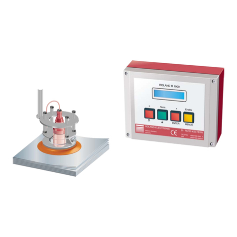
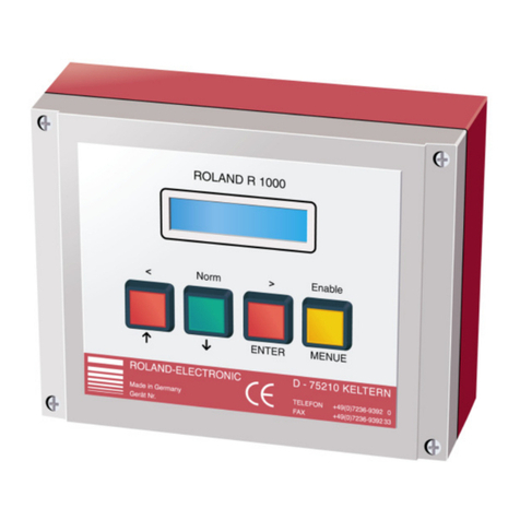
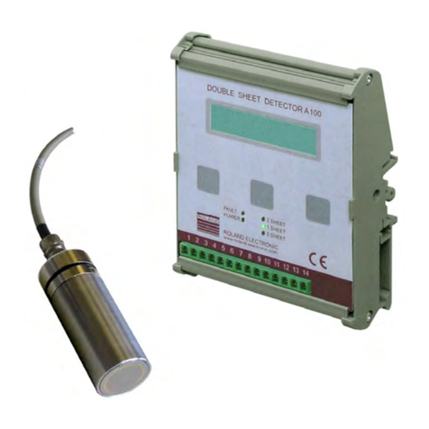
Roland R1000 series E20 User manual

DOUBLE SHEET CONTROL E20
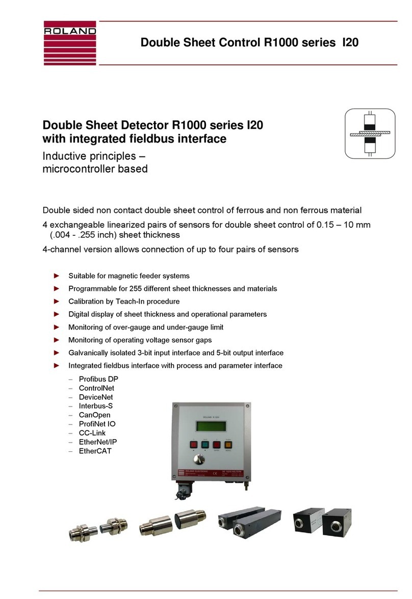
Double Sheet Detector
R1000-series E20
with integrated fieldbus interface
Pos: 1 /Do ppelblech/G eräte/E20/De ckblatt/D eckblatt @ 0 \mod_1 173195768953_501.doc @ 3188
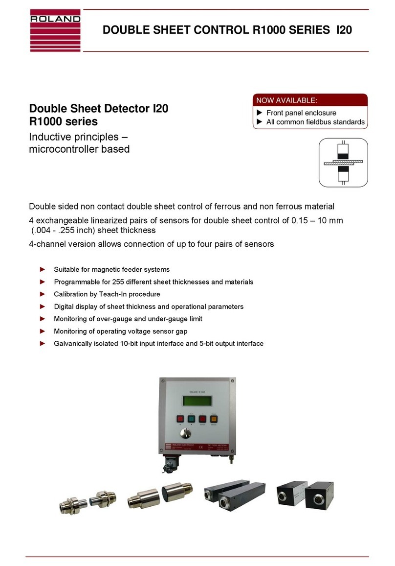
Electro magnetic principles –
microcontroller based
Single – sided contact double sheet control of ferrous materials
No force after measurement
4 exchangeable sensors for double sheet control of 0.1 – 12 mm (.004 - .472 inch) sheet
thickness
Optional version 4P allows connection of up to four identical sensors
Programmable for 255 different sheet thicknesses and materials
Calibration without sheet samples
Digital display of sheet thickness and operational parameters
Monitoring of over-gauge and under-gauge limit
Monitoring of operating voltage and sensor gap
Galvanically isolated 3-bit input interface and 5-bit output interface
Integrated fieldbus interface with process and parameter interface
− Profibus DP
− ControlNet
− DeviceNet
− Interbus-S
− CanOpen
− ProfiNet IO
− CC-Link
− EtherNet/IP
−EtherCAT
►
►
►
►
►
►
►

Copyright
©
2015ROLAND ELECTRONIC GmbH
Otto-Maurer-Str. 17
DE 75210 Keltern
All rights on this document are at Roland Electronic GmbH.
Reproduction (also partly), electronical coverage, translation, transmission to third parties,
only with our prior permission.
Subject to change without further notice.
===== En ded er Stückliste =====

Manual
Double Sheet Detector R1000 series UDK20
with integrated fieldbus interface
B0048191 / Rev. 1.5 Table of content
ROLAND ELECTRONIC GmbH · Otto-Maurer-Str. 17 · DE 75210 Keltern · Phone +49 (0)7236-9392-0 · Fax +49 (0)7236-9392-33 3
Declaration of conformity according to EC directives.....................................................................................5
1Safety advices ........................................................................................................................................7
1.1Declaration of icons .............................................................................................................................7
1.2Safety instructions and warnings for user............................................................................................7
1.3Intended use ........................................................................................................................................8
1.4Fieldbus terms......................................................................................................................................8
2Technical data ........................................................................................................................................9
2.1Technical data control unit UDK20 ......................................................................................................9
2.2Versions of the control unit UDK20....................................................................................................11
2.3Sensors..............................................................................................................................................12
2.4Sensor performance data (Measuring time) for ferrous (FE) material...............................................13
2.5Sensor data for non-ferrous (NF) material.........................................................................................14
2.6Sensor data (air gap) .........................................................................................................................15
2.7Sensor cables ....................................................................................................................................16
3System description..............................................................................................................................21
3.1Measurement principle.......................................................................................................................21
3.2General hints for process security .....................................................................................................21
3.3Control unit.........................................................................................................................................22
3.4Parameters of the control unit............................................................................................................22
3.5Application samples...........................................................................................................................27
4Mounting...............................................................................................................................................33
4.1General mounting instructions...........................................................................................................33
4.2Dimensions of the system..................................................................................................................34
4.3Mounting of sensors...........................................................................................................................37
4.4Automatic tool changer......................................................................................................................50
5Electrical installation ...........................................................................................................................51
5.1General instructions...........................................................................................................................51
5.2Configuration of connectors...............................................................................................................52
5.3Connecting diagram - examples........................................................................................................64
5.4Internal wiring of the Sensor-Switch-Box SSBUDK10.......................................................................67
6Communication with the PLC .............................................................................................................69
6.1Fieldbus specific messages...............................................................................................................69
6.2Data transmission communication.....................................................................................................70
6.3Process channel.................................................................................................................................71
6.4Parameter channel.............................................................................................................................86
6.5External I/O control ............................................................................................................................93
6.6Fieldbus configuration file..................................................................................................................98
7Start-up................................................................................................................................................103
7.1Initially applying power to the system ..............................................................................................103
7.2Operation .........................................................................................................................................104
7.3Configuration menu..........................................................................................................................105
7.4General information regarding the configuration .............................................................................107
7.5Changing, setting-up or checking the configuration.........................................................................107
Manual
Double Sheet Detector R1000 series UDK20
with integrated fieldbus interface
Table of content B0048191 / Rev. 1.5
4 ROLAND ELECTRONIC GmbH · Otto-Maurer-Str. 17 · DE 75210 Keltern · Phone +49 (0)7236-9392-0 · Fax +49 (0)7236-9392-33
7.6Program parameters ....................................................................................................................... 108
7.7System parameters......................................................................................................................... 114
7.8Data storage via serial RS232-interface ......................................................................................... 124
7.9Firmware update ............................................................................................................................. 124
8Operation............................................................................................................................................ 125
8.1Abbreviated operating instructions.................................................................................................. 125
8.2Entering a measurement program .................................................................................................. 126
9Fault messages, causes and remedies........................................................................................... 129
9.1Fault messages of the Sensor-Switch-Box ..................................................................................... 130
9.2Fault concerning memory................................................................................................................ 131
9.3Faults concerning Zero adjust......................................................................................................... 131
9.4Faults concerning Teach-In............................................................................................................. 132
9.5Faults concerning RS232 Transmission ......................................................................................... 132
9.6Faults concerning measuring operation.......................................................................................... 132
9.7Faults concerning keyboard............................................................................................................ 133
9.8Faults concerning supply voltage.................................................................................................... 133
9.9Faults Sensor Switch Box ............................................................................................................... 133
9.10Faults concerning PLC parallel inputs.........................................................................................133
9.11Faults fieldbus interface............................................................................................................... 134
9.12Other faults.................................................................................................................................. 134
10Maintenance....................................................................................................................................... 135
10.1Replacement of sensors.............................................................................................................. 135
10.2Exchange of control unit.............................................................................................................. 136
10.3Replacement of fuses.................................................................................................................. 137
10.4Data back up via the fieldbus interface or serial interface........................................................... 137
10.5Firmware update via RS232 interface......................................................................................... 137
10.6Short description RPP-XP software............................................................................................. 138
10.7Spare parts.................................................................................................................................. 138
11Technical records.............................................................................................................................. 139
11.1Fieldbus configuration files.......................................................................................................... 139
11.2Exchange of equipment............................................................................................................... 139
11.3Parameter channel commands.................................................................................................... 140
12Order data .......................................................................................................................................... 147
12.1Versions of control unit UDK20 ................................................................................................... 147
12.2System accessories..................................................................................................................... 148
12.3Sensors and accessories............................................................................................................. 149
12.4Cables.......................................................................................................................................... 149
12.5Cable plugs and cable sockets.................................................................................................... 149
12.6Other accessories........................................................................................................................ 150
13Appendix ............................................................................................................................................ 151
13.1System configuration form........................................................................................................... 151

Manual
Double Sheet Detector R1000 series UDK20
with integrated fieldbus interface
B0048191 / Rev. 1.5 Safety advices
ROLAND ELECTRONIC GmbH · Otto-Maurer-Str. 17 · DE 75210 Keltern · Phone +49 (0)7236-9392-0 · Fax +49 (0)7236-9392-33 5
Declaration of conformity according to EC directives
Manufacturer: Roland Electronic GmbH
Otto-Maurer-Str. 17
DE 75210 Keltern
Product name: UDK20
Product type: Double Sheet Detector
R1000 Series
Roland Electronic GmbH declares that the product listed above complies with the requirements of
the EMC directives listed below.
Applied Directives:
2006/95/EG Low Voltage Directive
EN61010-1: 2010
2004/108/EG: EMC Directive
EN61000-6-2: 2005-08 EN61000-6-4: 2007-01
Date of mark’s apposition: 16.02.2015
Keltern, 16.02.2015 Managing Director
Place, Date Signature Function of the signer
The declaration confirms the compliance with the cited directives. However, it is not any implied warranty of fitness for a
particular purpose especially as it may relate to product liability.
The safety instructions and warnings must be observed.
ISO 9001 : 2008
Reg.-no. 5152 QM08

Manual
Double Sheet Detector R1000 series UDK20
with integrated fieldbus interface
Safety advices B0048191 / Rev. 1.5
6 ROLAND ELECTRONIC GmbH · Otto-Maurer-Str. 17 · DE 75210 Keltern · Phone +49 (0)7236-9392-0 · Fax +49 (0)7236-9392-33
Blank page

Manual
Double Sheet Detector R1000 series UDK20
with integrated fieldbus interface
B0048191 / Rev. 1.5 Safety advices
ROLAND ELECTRONIC GmbH · Otto-Maurer-Str. 17 · DE 75210 Keltern · Phone +49 (0)7236-9392-0 · Fax +49 (0)7236-9392-33 7
1 Safety advices
1.1 Declaration of icons
Warning - general dangers!
Reference to imminent hazards, which can result in severe bodily harm or death.
Warning - dangers by high voltage!
Reference to imminent hazards due to electricity, which can result in severe bodily
harm or death.
Attention - Damage of construction units!
Reference to a potential imminent situation, which can result in damage to the
product or environs.
Note
Useful reference to an application or deepening information.
1.2 Safety instructions and warnings for user
This handbook contains all information required for the correct operation of the Roland equipment.
It has been written for technically qualified personnel.
Unauthorized tampering with the unit, especially ignoring the warnings in this handbook, can cause
malfunction and damage to the unit. Only authorized personnel should be allowed to make
changes to the unit and perform cable connections especially the power supply.
Should it be necessary, e.g. in case of service or repair, to make measurements within the unit,
then all customary accidents prevention procedures should be observed. Only professional
electrical tools should be used.
Note The factory pre-settings – especially the upper / lower limit values – have
been chosen such that an optimal machine protection is ensured.
Diverging settings can impair the machine protection.
Safety advice for persons with cardiac pacemakers!
Persons with cardiac pacemakers are to stay away from the sensors!
The strong magnetic / electromagnetic fields of the sensors can cause malfunction
of cardiac pacemakers and other such apparatus!
Warning When connecting or disconnecting the sensor plug you must stop
measurement!
Non-observance can result in a damage of the sensor!

Manual
Double Sheet Detector R1000 series UDK20
with integrated fieldbus interface
Technical data B0048191 / Rev. 1.5
8 ROLAND ELECTRONIC GmbH · Otto-Maurer-Str. 17 · DE 75210 Keltern · Phone +49 (0)7236-9392-0 · Fax +49 (0)7236-9392-33
1.3 Intended use
Flexible Manufacturing Systems in the sheet processing industry require reliable Double Sheet
Control systems in order to protect presses and other sheet processing machines against damage
caused by feeding multiple sheets.
The Double Sheet Detector R1000 UDK20 was specifically developed for this technical
environment. Depending on the application (type of material, thickness, sensor gap) the UDK20
can be used with up to four sensors. The reliable function of the Double Sheet Detector depends
therefore markedly on the selection of the correct sensors and the mounting of the sensors.
1.4 Fieldbus terms
Within this manual the following Field bus specific expressions are used:
Term used in the manual Field bus specific expression
Master Scanner
Slave ControlNet adapter / node
Baud rate Data rate
Bus address Mac ID / node address

Manual
Double Sheet Detector R1000 series UDK20
with integrated fieldbus interface
B0048191 / Rev. 1.5 Technical data
ROLAND ELECTRONIC GmbH · Otto-Maurer-Str. 17 · DE 75210 Keltern · Phone +49 (0)7236-9392-0 · Fax +49 (0)7236-9392-33 9
2 Technical data
2.1 Technical data control unit UDK20
Operating voltage: 24 VDC, +6 V / -2 V
Power consumption: 60 W (operation: <60 W, in idle: <10 W)
Switch on current: 10 Amps for 1 ms
External fuse: 5 Amps medium time lag
Weight: approx. 1.5 kg (3.30 lbs)
Ambient temperature: 0 - 50 °C (30 - 122° F)
Wall mount enclosure:
Protection category: IP65
Dimensions without screw fittings: approx. 225 x 240 x 80 mm (L x W x H)
approx. 8.85 x 9.45 x 3.15 inch (L x W x H)
Dimensions with screw fittings: approx. 225 x 360 x 80 mm (L x W x H)
approx. 8.85 x 14.2 x 3.15 inch (L x W x H)
Front panel enclosure:
Protection category: IP40 (inside)
IP65 (front cover)
Dimensions: approx. 240 × 240 × 120 mm (L x W x H)
approx. 9.45 × 9.45 × 4.7 inch (L x W x H)
Additional characteristics:
• 255 parameter sets memory
• Programming via pushbuttons or fieldbus
• 3 potential free optocoupler inputs 24 VDC with joint common
Specification:
min. switching voltage HIGH: 20 VDC
max. switching voltage HIGH: 30 VDC
min. switching voltage LOW: 0 VDC
max. switching voltage LOW: 8 VDC
• 5 potential free optocoupler outputs with positive external supply
Specification:
max. switching voltage: 50 VDC
max. switching current: 100 mA (internal current limitation)
max. switching power: 2.4 W (only resistor load)
Attention In case of inductive load a coil protection diode should be used.
Otherwise the signal output could be destroyed by the excess voltage
generated by switching the inductive load off.

Manual
Double Sheet Detector R1000 series UDK20
with integrated fieldbus interface
Technical data B0048191 / Rev. 1.5
10 ROLAND ELECTRONIC GmbH · Otto-Maurer-Str. 17 · DE 75210 Keltern · Phone +49 (0)7236-9392-0 · Fax +49 (0)7236-9392-33
• RS232 interface
Specification:
Baudrate: 4800
Data Bits: 8
Parity-Bit: None
Stop-Bit: 1
Hardware Handshake: None
The selection of the interface parameters with the exception of the baudrate is made via the
software and cannot be changed by user.
• Fieldbus interface
Profibus-DP interface according to the EN 50170, protocol version 1.10, max. baud rate
12 Mbit/s
ControlNet communication adapter (profile number 12) according to int. ControlNet
specification
DeviceNet communication adapter (profile number 12) according to ODVA specification
(group two only server)
Interbus-S - interface, certification protocol no. 440 (500 kbit/s; RS422)
CanOpen - interface, according to DS301 v4.02 compliant
ProfiNet IO – interface
CC-Link V1
EtherNet/IP
EtherCAT

Manual
Double Sheet Detector R1000 series UDK20
with integrated fieldbus interface
B0048191 / Rev. 1.5 Technical data
ROLAND ELECTRONIC GmbH · Otto-Maurer-Str. 17 · DE 75210 Keltern · Phone +49 (0)7236-9392-0 · Fax +49 (0)7236-9392-33 11
2.2 Versions of the control unit UDK20
The control unit article key is coded as follows:
1. Control unit UDK20 for connection of one sensor
A = Control unit
B = Type of fieldbus:
PR = Profibus-DP
CN = ControlNet
DN = DeviceNet (B-coded)
DNT = DeviceNet (A-coded)
IN = Interbus-S
CP = CanOpen (B-coded)
COP = CanOpen (A-coded)
PN = ProfiNet IO
CC = CC-Link
EN = EtherNet/IP
ET = EtherCAT
C = pluggable connections at control unit
D = Control unit in front panel enclosure
2. Control unit UDK20 for connection of up to two sensors,
all sensors are plug connected directly at the unit.
A = Control unit
B = Connection of up to 2 sensors
C = Type of fieldbus:
PR = Profibus-DP
CN = ControlNet
DN = DeviceNet (B-coded)
DNT = DeviceNet (A-coded)
IN = Interbus-S
CP = CanOpen (B-coded)
COP = CanOpen (A-coded)
PN = ProfiNet IO
CC = CC-Link
EN = EtherNet/IP
ET = EtherCAT
D = pluggable connections at control unit
E = Control unit in front panel enclosure
Basing on the article key shown above the following versions are available:
• UDK20-xx-S: Unit for connection of one sensor (max. 4 via SSB),
in industrial enclosure,
with data backup via Fieldbus or serial port
• UDK20-xx-S-FP: Unit as previous, but for front plate mounting
• UDK20-2PW-xx-S: Unit for connection of max. two sensors,
in industrial enclosure,
with data backup via Fieldbus or serial port
• UDK20-2PW-xx-S-FP: Unit as previous, but for front plate mounting
BCD
UDK20 xx--
S
-FP
BCDE
UDK20 xx--
S
-FP-2PW

Manual
Double Sheet Detector R1000 series UDK20
with integrated fieldbus interface
Technical data B0048191 / Rev. 1.5
12
ROLAND ELECTRONIC GmbH · Otto-Maurer-Str. 17 · DE 75210 Keltern · Phone +49 (0)7236-9392-0 · Fax +49 (0)7236-9392-33
2.3 Sensors
The sensor description has the following code:
A = Electro magnet
B = Eddy current
C = Diameter
D = Model
E = Thread
F = Quick disconnect
Fig. 1: Designation of sensors
2.3.1 Sensor PW42AGS
Fig. 2: Sensor PW42AGS
Technical data
FE - Measuring range
1)
: 0.2 – 4.0 mm .01 - .16 inch
NE - Measuring range
1)
: see sensor data for NF - material
Ambient temperature: 0 – 60 °C 30 – 140 °F
Class of protection: IP65
Weight: approx. 0.5 kg 1.1 lbs
Sensor cable: pluggable
1)
Related to single sheet thickness
W42A
G
S
A
B
C
D
E
F

Manual
Double Sheet Detector R1000 series UDK20
with integrated fieldbus interface
B0048191 / Rev. 1.5 Technical data
ROLAND ELECTRONIC GmbH · Otto-Maurer-Str. 17 · DE 75210 Keltern · Phone +49 (0)7236-9392-0 · Fax +49 (0)7236-9392-33 13
2.4 Sensor performance data (Measuring time) for ferrous (FE) material
In the following diagram the response time of the control unit for measurement is shown depending
in number of sensors activated by the program. In addition the response time depends on the
selected system parameter “FE-Measure”, the actual sheet thickness, the nominal sheet thickness
and the upper limit (up).
System parameter „FE-Measure“
• „fast“
The actual response time depends on the measured sheet thickness, the nominal thickness
and the upper limit (up).
The maximum response time is limited by the nominal thickness and the upper limit (see
diagram and example).
Advantage: maximum response time is low.
Disadvantage: In case of measuring results larger than the double sheet threshold, the text
“2-sheet” is issued instead of the actual measurement value.
• „normal“
The actual response time depends on the measured sheet thickness.
The maximum response time corresponds to the maximum sheet thickness.
Example 1:
• System parameter “FE-Measure: fast”
• Measurement with one sensor
• Nominal thickness 1.0 mm = 100%
• upper limit (UP) 120% (=1.2 mm)
Actual sheet thickness = 1 mm actual response time = 58 ms
Actual sheet thickness = 2 x 1 mm actual response time = 62 ms
Actual sheet thickness = 7 x 1 mm (sensor on stack) actual response time = 62 ms
The maximum response time is 62 ms (with “up“ = 120%). This means that after the signal "measurement start" was issued
(max. 30ms), it will take 62 ms until the result of the measurement is available as output signal (with “up“ =120%).
Example 2:
• System parameter “FE-Measure: normal”
• Measurement with one sensor
• Nominal thickness 1.0 mm = 100%
• upper limit (UP) 120% (=1.2 mm)
Actual sheet thickness = 1 mm actual response time = 58 ms
Actual sheet thickness = 2 x 1 mm actual response time = 68 ms
Actual sheet thickness = 7 x 1 mm (sensor on stack) actual response time = 80 ms
The maximum response time is 80 ms (with “up“ = 120%). This means that after the signal "measurement start" was issued
(max. 30ms), it will take 80 ms until the result of the measurement is available as output signal (with “up“ =120%).
Note The advantage in measuring time is significant, if the thickness of material
is considerably lower than the measuring range of the sensor.

Manual
Double Sheet Detector R1000 series UDK20
with integrated fieldbus interface
Technical data B0048191 / Rev. 1.5
14 ROLAND ELECTRONIC GmbH · Otto-Maurer-Str. 17 · DE 75210 Keltern · Phone +49 (0)7236-9392-0 · Fax +49 (0)7236-9392-33
The data for 2 sensors apply in the so-called sequencer mode.
Fig. 3: System reaction time PW42AGS
2.5 Sensor data for non-ferrous (NF) material
The amount of eddy current generated and the corresponding energy absorption is directly related
to the electrical conductivity. High values of electrical conductivity and the corresponding strong
eddy currents reduce the controllable sheet thickness.
Note The system reaction time for non-ferrous materials is constant at 85 ms.
This applies for measurements with 1 sensor as well as for measurements
with 2 sensors (in sequencer mode).
Material Conductivity (MS) Max. thickness for single sheet (mm)
Austenite 1.41 2.0
Bronze 8.5 4.0
Zinc 16.3 4.0
AL-Alloy 18.2 4.0
AL-Alloy 25.2 4.0
AL 34.2 4.0
CU-Alloy 43 3.5
CU 57.5 3.0
Standard working range
Single sheet thickness
(Nominal thickness) [mm]
40
50
60
70
80
90
100
110
120
130
140
150
160
170
2 Sensors
1 Sensor
PW42AGS
150 %
120 %
0,5 1,0 1,5 2,0 2,5
03,0 3,5 4,0

Manual
Double Sheet Detector R1000 series UDK20
with integrated fieldbus interface
B0048191 / Rev. 1.5 Technical data
ROLAND ELECTRONIC GmbH · Otto-Maurer-Str. 17 · DE 75210 Keltern · Phone +49 (0)7236-9392-0 · Fax +49 (0)7236-9392-33 15
2.6 Sensor data (air gap)
Double sheet thresholds above 120% reduce the performance of the system with regard to air gaps
between the sheets and increase the systems reaction time according to the diagram.
Air gaps influence the performance negatively because air has - in contrast to steel - a high
resistance to the magnetic flux. Therefore, air gaps reduce the performance of the system
considerably (see chapter “3.1 Measuring principle and conditions influencing measurement
accuracy“).
For reliable double sheet monitoring there should be no air gap between sheet and sensor and also
between the sheets. The most reliable double sheet recognition results, if no air gaps exist. These
aspects should be specifically observed when mounting the sensors.
The eddy current principle is more forgiving with regard to air gaps than the electromagnetic
principle. However, for most reliable performance precaution should be taken to avoid air gaps
between sensor and sheet. The permissible air gaps between first and second sheet can be slightly
higher than for steel.
The influence of air gaps are described in the following diagrams.
Max. air gap between sensor and first sheet (1st air gap)
Max. air gap between first and second sheet (2nd air gap)
The data apply for a set upper limit of 120%.
234567
0,2
0,4
0,6
0,8
1,0
1,2
1,4
1,6
1,8
2,0
2,2
2,4
2,6
2,8
3
,
0
Sheet thicknes
s
[mm]
1.
0,5 1,5 2,5 3,5 4,5 5,5 6,5
PW42AGS
1
.
s
t
a
i
r
g
a
p
[
m
m
]
NF
FE
234567
1
2
3
4
5
6
7
8
9
10
[mm]
0,51,52,53,54,55,56,5
PW42AGS
FE
NF
2.
11
2
.
n
d
a
i
r
g
ap
[
mm
]

Manual
Double Sheet Detector R1000 series UDK20
with integrated fieldbus interface
Technical data B0048191 / Rev. 1.5
16 ROLAND ELECTRONIC GmbH · Otto-Maurer-Str. 17 · DE 75210 Keltern · Phone +49 (0)7236-9392-0 · Fax +49 (0)7236-9392-33
2.7 Sensor cables
Suitable cable type:
• Superflex (C)Y PURKOMBI 2 x 1,0 mm² + 4 x 2 x 0,25 mm²
• The cable is oil-proof and suitable for drag chains
- Bending radius flexible use min. 110 mm
Cable marking:
• for PW42AGS:
SCPWS-GG (straight receptacle at the sensor)
SCPWS-GW (right angle receptacle at the sensor)
The cable has quick disconnects at both ends. The plug at the control unit side is always straight.
Note The sensor cable is an active component of the sensor technology. The
technical data of the sensors is valid only if the cable specification is met. A
shielded cable (2 x 1,0 mm² + 4 x 2 x 0,25 mm²) must be used. The cable
length can be to up to 50 m. Following the rule "the shorter the better"
generally leads to better measuring results.
2.7.1 Sensor cable SCPWS for PW42AGS sensor
Cable socket, sensor side Cable plug, unit side
Socket contacts Plug contacts
Right angle cable socket, sensor side
1 grey
2 pink
3 red
4 black / violet
5 blue
6 brown 1 mm²
7 brown
8 white 1 mm²
9 green
Enclosure blank (Shield)
Fig. 4: Sensor cable SCPWS
3
45
6
7
81
9
54
26
24
3
45
6
7
81
9
60

Manual
Double Sheet Detector R1000 series UDK20
with integrated fieldbus interface
B0048191 / Rev. 1.5 Technical data
ROLAND ELECTRONIC GmbH · Otto-Maurer-Str. 17 · DE 75210 Keltern · Phone +49 (0)7236-9392-0 · Fax +49 (0)7236-9392-33 17
to Sensor to control unit
Cable socket Bootlace ferrules
1 grey
2 pink
3 red
4 black / violet
5 blue
6 brown 1 mm²
8 white 1 mm²
7 brown
9 green
Enclosure blank (Shield)
Cable types for the sensor PW42AGS (order data):
• SCPWS-GG (straight receptacle at the sensor)
• SCPWS-GW (right angle receptacle at the sensor)
The standard length is 5 meter. Cable length up to 50 meter made to order, longer cables please
enquire.
Note In particular with larger lengths the sensor cable should not be placed
directly adjacent to cables with large noise potential.
The cable is drag cable suitable and oil resistant.
Cable type:
• Superflex (C)Y PURKOMBI 2 x 1,0 mm² + 4 x 2 x 0,25 mm²
pink
red
black
violet
blue
brown *
white *
brown
green
1
2
3
4
5
6
8
7
9
PW42AGS
1
2
3
4
5
6
8
7
9
1
2
3
4
5
6
8
7
9
1
2
3
4
5
6
8
7
9

Manual
Double Sheet Detector R1000 series UDK20
with integrated fieldbus interface
Technical data B0048191 / Rev. 1.5
18 ROLAND ELECTRONIC GmbH · Otto-Maurer-Str. 17 · DE 75210 Keltern · Phone +49 (0)7236-9392-0 · Fax +49 (0)7236-9392-33
2.7.1.1 Installation of the sensor cable
Fig. 5: Installation of the sensor cable
The following instructions are essential when installing the sensor cable:
1. Take notice of the keyway on the sensor head! Do not use during tightening a pipe
wrench or similar tools, since the pin contacts could be destroyed.
2. Be careful about the screw-in depth! Turn the cable socket until the edge flushes with
the sensor head. (see the O-ring)
3. Tighten the securing grub screw after connecting the cable socket with an allen
wrench (1.5 mm)!
Note The securing grub screw is not present at every cable type
2.7.2 Sensor cable extensions
A sensor cable extension can be relatively easy made. For this a SCPWS-GG or SCPWS-GW
cable is always needed.

Manual
Double Sheet Detector R1000 series UDK20
with integrated fieldbus interface
B0048191 / Rev. 1.5 Technical data
ROLAND ELECTRONIC GmbH · Otto-Maurer-Str. 17 · DE 75210 Keltern · Phone +49 (0)7236-9392-0 · Fax +49 (0)7236-9392-33 19
2.7.3 Cable for Sensor-Switch-Box SSBUDK10
The cable SVCPWS-SSBUDK10 is used for connecting the control unit to the Sensor Switch Box.
The following pin configuration and dimensions apply:
to Sensor-Switch-Box to unit
Cable socket Cable plug
1 white
2 green
3 brown
4 yellow
5 grey
Enclosure blank (Shield)
1 white
2 green
3 brown
4 yellow
5 grey
Enclosure blank (Shield)
to Sensor-Switch-Box to unit
Cable socket Cable plug
1 white
2 green
3 brown
4 yellow
5 grey
Enclosure blank (Shield)
Cable type for SSBUDK10 (order data):
• SVCPWS-SSBUDK10
The standard length is 5 meter.
Note For the connection of the SSBUDK10 to the sensor PW42AGS the
SCPWSGG or SCPWS-GW are used.
2
3
5
4
51
22
22
2
3
5
4
1
2
3
4
5
grey
white
brown
green
yellow
SSBUDK10
1
2
3
5
4
1
2
3
5
4

Manual
Double Sheet Detector R1000 series UDK20
with integrated fieldbus interface
System description B0048191 / Rev. 1.5
20 ROLAND ELECTRONIC GmbH · Otto-Maurer-Str. 17 · DE 75210 Keltern · Phone +49 (0)7236-9392-0 · Fax +49 (0)7236-9392-33
Blank page
Other manuals for R1000 series E20
7
This manual suits for next models
1
Table of contents
Other Roland Security Sensor manuals

Roland
Roland R1000 series E20 User manual

Roland
Roland Double Sheet Detector R1000 Series User manual

Roland
Roland ZBX-540E User manual

Roland
Roland R1000 series E20 User manual

Roland
Roland udk20 User manual

Roland
Roland R1000 series E20 User manual

Roland
Roland R4000 User manual

Roland
Roland R100 Series User manual

Roland
Roland R1000 series E20 User manual

Roland
Roland Double Sheet Detector I100 User manual