Rotech TRISTAR J18 AT User manual

1
Vehicle Access Control
Pedestrian Access Control
Safety & Security Equipment
T: +61 7 3205 1123 www.rotech.com.au e: info@rotech.com.au
TRISTAR J18 AT
TURNSTILE Instructions
(V11/19)
Unpacking the turnstile
First remove the top cover of the wooden crate, then the side cover. The turnstile inside the
crate can now be pulled out of the crate. Do not remove the plastic wrapping until the turn-
stile is ready to be used as this will prevent any damage to the stainless steel cabinet.

2
1. Introduction
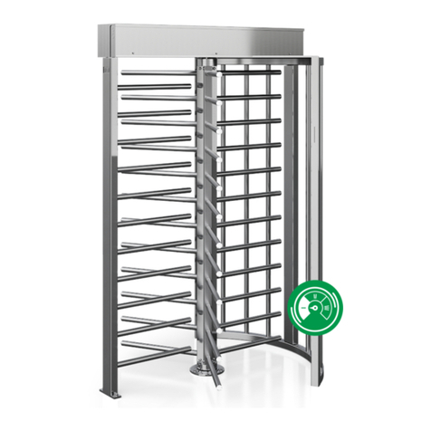
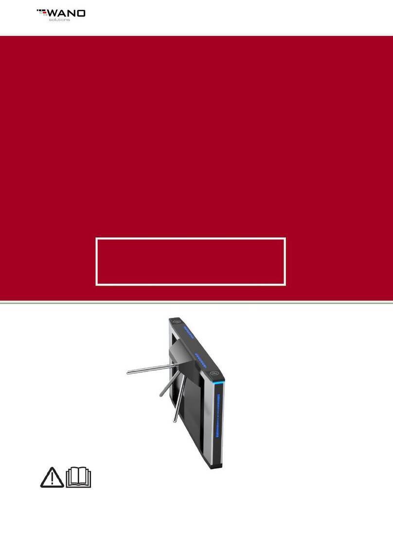
The TriStar J18 AT automatic turnstile is designed for use in high volume traffic areas to
control pedestrian traffic. Any type of access control or ticketing system can be used
to activate the turnstile. The turnstile is operated using a DC brushless motor which
ensures a smooth operation and the inbuilt encoder guarantees exact positioning of
the arm. When connected to the fire alarm or other emergency system the active
arm drops allowing fast exit from the building. During a power failure the arm drops
and will automatically reposition itself when the power is restored.
2. Technical Specifications
Model No
TriStar J18 AT
Throughput 25 users per minute
Channel width
550-600 mm
Duty cycle
100%
Operating input
Potential free N/O
MCBF
300 million operations
Safety devices
Arm drops in emergency
IP rating
IP 55 standard
Signal time out
Adjustable up to 20 seconds
Power supply
220vac +- 10%
Motor voltage
24vdc
Power consumption
50W
Working environment
-30
℃
~+70
℃
Relative humidity
95%
3. Standard features
3.1 Easy set up using the LED display.
3.2 Accurate positioning using the encoder.
3.3 The control panel shows the status of all key components.
3.4 Multiple input and output ports, can be configured to user requirements.
3.5 When the arm is returning to the default position it slows so that there is no
mechanical force on the internal components.
3.6 Suitable for both Indoor and outdoor.
3.7 The control panel indicates the current status.
3.8 The rotation speed of the arm while entering the turnstile can be adjusted.
3.9 If the arm is forced without presenting a card the arm locks for 4 seconds.
3.10 The turnstile can be opened by two input signals (signals can be input by access
controller, push button or other equipment).
3.11 Indicator lights: When the turnstile is ready to read the card, the light in the middle will
be yellow. After reading card the upper blue light will come on. If someone tries to
push the arm without permission, the red light will comeon.
3.12 Single direction or bi direction is optional.
3.13 In an emergency or power failure the active arm will drop. The control panel can be
3
connected to the fire alarm or any type of emergency input. When the power is
restored or the emergency input is switched off the arm automatically returns to the
default position
3.14 The J18 AT has a memory input that remembers how many access cards have
been presented and does not lock the turnstile until all users who have presented
their cards have passed through the turnstile.
3.15 If no pedestrian passes through the turnstile after swiping their card the turnstile will
return to lock mode after a pre-set time (time adjustable).
4. Optional features
4.1 Voice prompt and display screen available.
4.2 An external counter can be connected to count thenumber of people passing
through the turnstile.
4.3 RS485 communication, PC command through serial port
4.4 Audible and / or visual alarm to indicate attempted forcedentry.
5. Mechanical installation
5.1 The turnstile should be mounted on a smooth level surface; a concrete base is
preferred especially for outdoor applications.
5.2 Two hold down bars are provided and these should be fixed with M12 x 100 mm
expansion bolts.
5.3 The conduit entry can be inside the leg of the turnstile or through the cabinetwall.
6. Electrical Installation
6.1 All electrical connections must be made by a qualified electrician in accordance with
Australian wiring regulation AS/NZS 3000 2007.
6.2 The turnstile requires a 5 amp 240vac power supply fitted with an earth leakage unit
and a suitable circuit breaker.

4
7. Z3D001A Control Panel

5
8. Set up Instruction
After power-up, the LED on the main board will display the version number of the
current software. For example, the display shows 0-01, indicating that the current
software is V01, The display will then show : 2017-12-12-10-41-30 (year, month, day,
hour, minute, second). After this display the turnstile arm will automatically rotate to
the normal working position after completing a self test, the turnstile is now ready set
the parameters.
8.1 Main board control buttons and LED display
Figure 11 Digital Tube
8.2 Parameter set up
For example: If you wish to change parameter P-01 (counting function)
Press the “Set / Confirm / Save” button for 3 seconds to enter the set up mode.
If you change the value of the parameter to 1 by pressing the "Up" and "Down"
keys, this will enable the counting function and finally press the
"Set/Confirm/Save" button to save the parameter.
If you want to set other parameters, after displaying P-01, you can change the type
of the parameter by "Up" and "Down".

6
Parameter
Description
Value
Valu
e
P-00
Example
P-01
Counting function selection
0
Disable
1
Enable
P-02
To allow access in entry
direction
0
Disable
1
Enable
P-03
To allow access in exit
direction
0
Disable
1
Enable
P-05
Reserved
P-06
Entry control by
0
Swiping card
1
Free wheel
P-07
Exit control by
0
Swiping card
1
Free wheel
P-08
Rotation speed of arm during
self-check at startup
Value is 0-100, the larger the value, faster
the speed, default 70
P-09
Rotation speed when
operating the turnstile
Value is 0-70, default 50
P-10
Reset speed when the bar is
off center
The value is 0-50. The larger the value, the
more accurate the accuracy, but the
greater the jitter, default 34
P-11
Speed setting after the arm
locked
The value is 0-70, default is 40
P-12
Recovery time of the first lock
(recovery time of the first forced
lock l: the recovery time of the
second lock is 4 times of the first,
and the recovery time of the N
times lock is (n-1)*4 times of the
recovery time of the first lock ).
Maximum value 20S, defaulted 2S
P-13
Waiting time after swiping
card
Maximum value 20S, default 8S
P-14 to P-24
Reserved
P-25
Zero setting
P-26
Program version selection
8.3 Interface instruction

7
Interface
Name
Pin definition
IO3
The reversed panel
status indicator
+12V —+12V output, power for indicator
GND — Power GND
GND —Power GND
FRL — Reversed red indicator
FBL —Reversed blue indicator
FYL —Reversed yellow indicator
+12V - +12V output, powering the panel status
indicator
GND
GND
FRL - status indicator red light
FBL - status indicator blue light
FYL - status indicator yellow light
I04
Forward panel status
indicator
+12V —+12V output, power for indicator
GND —Power GND
GND —Power GND
ZRL —Forwarded red indicator
ZBL —Forwarded blue indicator
ZYL —Forwarded yellow indicator
+12V - +12V output, powering the panel status
indicator
GND
GND
ZRL - status indicator red light
ZBL - status indicator blue light
ZYL - status indicator yellow light
IO5
Alarm interface
ALM —Alarm output signal
ALM —Alarm output signal ALM
GND
IO7
Forward, reversed
counting
Arm drop signal input
B1 —Reserved
B2 —Reserved
EX2 —Reserved
EX1 —Reserved
FCNT —Reverse pass counting
ZCNT —Forward pass counting
LOCK —Arm drop signal input(fire arm drop)
IO9
Communication
interface
485 A
485 B
8.4 Digital zero setting method
Power on, waiting for the self-test to be completed.
Press the “Set/Confirm/Save” button for 3 seconds to enter the set up interface,
then use the up and down keys to adjust the parameter type to “P-25”, and
finally press the “Set/Confirm/Save” button within 5 seconds.
Adjust any one of the arms manually to the "closed position", the gate is
automatically reset, the turnstile will use the newly set zero point after the reset.
9. Trouble shooting
Problem Action

8
No response when triggered Close cover
Arm is not returning to start position Check cam for wear if OK add lubricant
Arm is slow returning to start position Adjust tension springs
Emergency arm drop off not working or arm
won’t lock in position when power on Adjust the position of the release solenoid
Arm does not automatically lock in position Adjust position of photocell on disc.

9
Turnstile J18 AT Dimensions
NOTE: The concrete pad should be 20Mpa (min) 150 mm thick, cured for 7 days on a suitably
compacted foundation. Hold down anchors (4) to be 12mm dia x 100mm into the concrete.
Control panel in Entry Leg of Turnstile.

Cleaning and Maintenance of Stainless steel cabinet
Initial cleaning, wipe down exterior surfaces with thinners, then polish with stainless
steel polish
If outdoor polish every 3 months
In wet environments (daily cleaning with water) polish every 4 weeks to prevent “tea
staining”
Polish every week if salt spray present