Gatan PIPS II 695 Guide

Pr
e
e
cisio
Ow
n
G
5
P
n Io
n
n
er’s
M
G
atan,
I
5
794 W. Las
P
leasanton,
C
n
Poli
s
M
anual
a
I
nc.
s
Positas Bl
v
C
A 94588
s
hing
a
nd Us
e
Part N
u
v
d. Tel.
(
Fax.
PIPS
Syst
e
e
r’s G
u
u
mber 695.
8
Revisi
o
3/15
/
(
925)463-0
2
(925)463-0
2
II
e
m
u
ide
8
2001
o
n 4.0
/
2014
2
00
2
04

2
PIPS II Owners Manual and Users Guide
PIPS II
O
Sy
m
S
s
ym
I
M
in
s
pr
O
wners Ma
n
T
h
m
h
a
e
q
m
bols a
n
Y
o
p
r
S
YMBOL
C
A
m
bol is ma
r
M
PORTAN
T
s
tructions
oduct. Rev
n
ual and Us
e
S
h
is chapter
anual. Gata
n
a
rm to your
s
q
uipment as
w
n
d Atte
n
o
u must be
a
r
ovides vari
o
REFERE
N
IEC 60417
IEC 60417
IEC 60417
IEC 60417
A
UTION -
D
r
ked.
T
- For
please re
f
iew this do
c
e
rs Guide
S
afety
presents a
n
, Inc., reco
s
elf or the e
q
w
ell.
n
tion S
y
a
ware of sa
f
o
us procedu
r
N
CE
-5031 (200
2
-5032 (200
2
-5033 (200
2
-5017 (200
6
D
ocument
a
Re
g
ulator
y
f
er to th
e
c
ument in f
u
Infor
m
summary
o
mmends fo
l
q
uipment. P
y
mbols
f
ety when y
o
r
es that requ
i
2
-10)
2
-10)
2
-10)
6
-08)
a
tion must
b
y
Complia
n
e
R
e
g
ulat
o
u
ll before i
n
m
atio
n
o
f the safe
l
lowing all
s
lease follo
w
o
u install an
d
i
re careful a
t
b
e consult
e
n
ce and
o
r
y
Pamp
h
n
stallin
g
an
d
n
ty symbols
s
afety prec
a
w
all warnin
g
d
use this s
y
ttention to
p
D
D
A
c
u
B
a
l
c
u
E
T
e
d in all c
a
Safet
y
inf
o
h
let provi
d
d
operatin
g
throughou
t
a
utions to pr
g
s marked
o
y
stem. This
G
p
recautions.
D
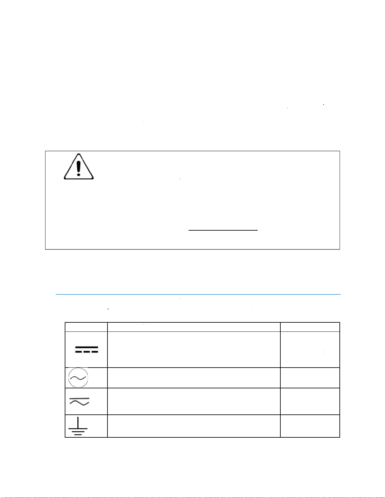
ESCRIPTI
O
D
irect curre
n
A
lternating
u
rrent
B
oth direct a
n
l
ternating
u
rrent
E
arth (gro
u
ERMINAL
a
ses where
o
rmation
d
ed with
g
this produ
3
t
this
r
event
o
n the
G
uide
O
N
n
t
n
d
u
nd)
this
and
this
ct.
PIPS II
O
Pr
o
O
wners Ma
n
o
duct S
a
R
e
p
r
u
s
c
o
w
i
lo
w
a
a
n
n
ual and Us
e
IEC 60417
IEC 60417
IEC 60417
IEC 60417
IEC 60417
ISO 7000-
0
a
fety Inf
o
e
view the f
o
r
oduct, or a
n
s
e the produ
c
o
mponent p
r
i
th safety s
y
cations wit
h
a
rnings and
n
d frequenc
y
e
rs Guide
-5019 (200
6
-5020 (200
2
-5007 (200
9
-5008 (200
9
-5041 (200
2
0
434B (200
4
o
rmatio
o
llowing pr
e
n
y products
t
c
t only as s
p
r
oduct use
r
y
mbols, writ
t
h
in the unit.
instruction
s
y
of your
p
6
-08)
2
-10)
9
-02)
9
-02)
2
-10)
4
-01)
n
e
cautions to
t
o which it
i
p
ecified. Re
a
manuals an
d
t
en warning
Save this d
o
s
marked o
n
p
ower sour
c
avoid injur
y
i
s connecte
d
ad all safet
y
d understan
s, and cauti
o
ocument fo
r
n
the equip
m
c
e matches
P
C
T
F
T
O
O
C
p
e
l
C
s
u
C
d
m
c
o
c
a
s
y
m
C
m
y
and preve
n
d
. To avoid
p
y
informatio
n
n
d the preca
u
o
ns before
a
r
future refe
m
ent. Ensur
e
the voltag
e
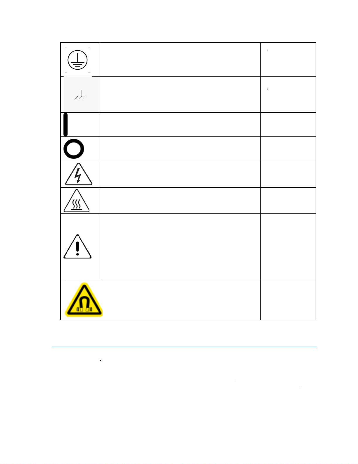
P
rotective
C
onductor
T
erminal
F
rame or ch
a
ERMINAL
O
n (Power)
O
ff (Power)
C
aution,
ossibility o
f
l
ectric shoc
k
C
aution,
u
rface
C
aution -
ocumentati
o
m
ust be
o
nsulted in
a
a
ses where
t
y
mbol is
m
arked
C
aution,
m
agnetic fiel
n
t damage t
o
p
otential ha
z
n
provided
i
u
tions asso
c
a
ccessing p
a
rence. Foll
o
e
that the v
o
e
and freq
u
4
a
ssis
f
k
hot
o
n
a
ll
t
his
d.
o
this
z
ards,
i
n the
c
iated
a
rts or
o
w all
o
ltage
u
ency
PIPS II
O
O
wners Ma
n
in
ki
n
p
r
c
a
Da
n
spe
c
Do
N
do
n
To
A
con
d
ma
k
gro
u
Do
n
Dis
c
Sho
u
wip
e
Wa
r
not
ter
m
Ele
c
stati
clot
h
Wh
e
stra
p
disc
h
To
a
an e
n
ual and Us
e
scribed on t
h
n
d through
r
esent. Con
d
a
use fire, ele
c
ng
er: Disco
n
c
ified on the
N
ot Operat
e
n
ot operate t
h
A
void the
R
d
ensing co
n
k
e connectio
n
u
nded plug (
t
n
ot operate
i
c
onnect all e
u
ld a leak o
c
e
to clean u
p
r
nin
g
:To a
v
make conn
e
m
inal. See th
e
c
tronic com
p
c electricit
y
h
ing or wor
k
e
n installing
p
s and ant
h
arge.
a
void injury
x
plosive at
m
e
rs Guide
h
e equipme
n
the openin
d
uctive fore
i
c
trical shoc
k
n
nect power
product's r
a
e
Without
C
h
is product
w
R
isk of Ele
c
n
ditions. W
h
n
s to a grou
n
t
hird groun
d
i
n wet, dam
p
xternal pow
c
cur, remov
e
p
the spill.
v
oid electri
c
e
ctions to t
e
e
product us
p
onents on p
. Ordinary
a
k
environme
the board i
n
i-static ma
t
, fire hazar
d
m
osphere.
n
t's electric
a
gs in the
e
i
gn objects
c
k
, or damag
e
before repl
a
a
ting label.
overs: To a
v
w
ith any re
m
c
tric Shock:
h
en supplyi
n
n
ded main.
A
d
ing pin).
p
, or conden
s
er connecti
o
e
power fro
m
c
al hazards (
e
rminals o
u
er manual f
o
rinted circu
i
a
mounts of
s
nt can dam
a
n
a system,
y
t
s to prev
e
d
, or explos
i
a
l rating lab
e
e
quipment.
D
c
ould prod
u
e
your equip
a
cing fuses
a
v
oid electri
c
m
oved enclo
s
Do not op
e
n
g power
t
A
lways use
a
s
ing conditi
o
o
ns before s
e
m
PIPS. Use
(
heat, shock
u
tside the r
a
o
r correct c
o
i
t boards are
s
tatic electri
a
ge the elect
r
y
ou must u
s
e
nt damage
i
on, do not
o
e
l. Never p
u
D
angerous
v
u
ce a short
c
ment.
a
nd only use
c
shock or
f
s
ure covers
o
e
rate in we
t
t
o the syst
e
a
power cab
l
o
ns.
e
rvicing.
paper towe
l
and/or fire
h
a
nge specifi
e
o
nnections.
e
extremely
s
city genera
t
r
onic equip
m
s
e anti-static
due to e
o
perate this
u
sh objects
o
v
oltages m
a
c
ircuit that
c
value
f
ire hazard,
o
r panels.
t
, damp, or
em
, always
le with
a
l
s or Kem
h
azard), do
e
d for that
s
ensitive to
t
ed by your
m
ent.
grounding
e
lectrostatic
product in
5
o
f any
a
y be
c
ould

6
PIPS II Owners Manual and Users Guide
Preface
Copyright and Trademarks
© 2007 Gatan, Inc. The Gatan logo is a registered trademark of Gatan, Inc.
The product names AutoFilter, BioScan, Clipring, DigiPEELS, DigiScan,
DigitalMicrograph, DigitalMontage, Duo Mill, DuoPost, Gatan LowDose,
GIF, Hexlok, Hexring, HotHinge, MSC, PECS, PIPS, Toggle Tilt, and
Whisperlok are trademarks belonging to Gatan, Inc.
The PIPS is protected by US Patents 4,272,682; 5,009,743; and 5,472,566.
Other patents are pending.
Disclaimer
Gatan, Inc., makes no express or implied representations or warranties with
respect to the contents or use of this manual, and specifically disclaims any
implied warranties of merchantability or fitness for a particular purpose.
Gatan, Inc., further reserves the right to revise this manual and to make
changes to its contents at any time, without obligation to notify any person or
entity of such revisions or changes.
Support
Gatan, Inc. provides free technical support via phone, fax, and electronic mail.
To reach Gatan technical support, contact the facility nearest you, or send
USA, Canada and
Latin America Field Service
Gatan, Inc.
5794 W. Las Positas Blvd.
Pleasanton, CA 94588
Tel. +1 (925) 224-7360
Toll Free: +1 888-887-3377
Fax. +1 (925) 463-0204
Contact:service @gatan.com
Parts and Consumables
Gatan, Inc.
5794 W. Las Positas Blvd.
Pleasanton, CA 94588
Tel. +1 (925) 224-7314
Fax. +1 (925) 463-0204
Contact:service @gatan.com

7
PIPS II Owners Manual and Users Guide
Factory Service
Gatan, Inc.
780 Commonwealth Drive
Warrendale, PA 15086
Tel. +1 (724) 779-2552
Toll Free: +1 888-778-7933
Fax. +1 (724) 776-3360
Contact:service @gatan.com
Asia and Pacific Rim Nippon Gatan
Hibarigaokaminamikan 6F
3-27-11 Yato-cho, Nishi-Tokyo-Shi
Tokyo 188-0001 Japan
Tel: 011-81-424-38-7230
Fax: 011-81-424-38-7228
Contact:[email protected]
Gatan Singapore
10 Eunos Road 8
#12-06
Singapore Post Centre
Singapore 408600
Tel: (65) 6293 3160
Fax: (65) 6293 3307
Contact: [email protected]
Europe Gatan GmbH, München Germany
Ingolstadterstr. 12
D-80807 München
Germany
Tel. +49 89 358084-0
Fax. +49 89 358084-77
Contact: [email protected]
Gatan UK
25 Nuffield Way
Abingdon, OX14 1RL
United Kingdom
Tel. +44 1235 540160
Fax. +44 1235 540169
Contact: [email protected]

8
PIPS II Owners Manual and Users Guide
Gatan France
3bis, Chemin du Haut Breuil
78113 GRANDCHAMP
FRANCE
Tel : 33 1 34 94 44 07
Mobile : 33 6 80 13 51 39
Fax : 33 1 34 87 16 68
Contact: [email protected]
Returns
If there is a need to return equipment to the factory, please call Gatan to obtain
a Returned Merchandise Authorization Number (RMA #). This RMA number
must appear on your shipping document, to help in tracking and to ensure that
proper action will be taken to repair or replace your equipment.

9
PIPS II Owners Manual and Users Guide
Table of Contents
Safety Information....................................................................................................................... 3
Symbols and Attention Symbols ............................................................................................. 3
Product Safety Information ..................................................................................................... 4
Preface......................................................................................................................................... 6
Copyright and Trademarks...................................................................................................... 6
Disclaimer................................................................................................................................ 6
Support..................................................................................................................................... 6
Returns..................................................................................................................................... 8
Table of Contents........................................................................................................................ 9
List of Figures ........................................................................................................................... 12
List of Tables............................................................................................................................. 16
1. Overview......................................................................................................... 17
1.1. Features of the Precision Ion Polishing System.............................................. 17
1.2. Main Work Chamber ...................................................................................... 20
1.3. Vacuum System.............................................................................................. 21
1.4. Electrical system............................................................................................. 24
1.5. The Standard Operating Mode........................................................................ 25
2. Installation....................................................................................................... 26
2.1. Site Requirements........................................................................................... 26
2.2. Unpacking....................................................................................................... 27
2.3. Installation....................................................................................................... 28
3. Operation......................................................................................................... 34
3.1. Graphical User Interface (GUI)...................................................................... 34
3.2. Start-up Procedure .......................................................................................... 59
3.3. Specimen Loading and Unloading.................................................................. 61
3.4. Specimen Viewing.......................................................................................... 63
3.5. Shutter Control................................................................................................ 64
3.6. Specimen Rotation.......................................................................................... 64
3.7. Centering the x-y Stage................................................................................... 65
3.8. Centering the Point of Interest........................................................................ 66
3.9. Gun Gas-flow Adjustment.............................................................................. 69

10
PIPS II Owners Manual and Users Guide
3.10. Aligning the Beam.......................................................................................... 71
3.11. Ion-beam Modulation...................................................................................... 75
3.12. Manual Shutdown Procedure.......................................................................... 78
4. Specimen Preparation ..................................................................................... 79
4.1. Disk Preparation.............................................................................................. 79
4.2. Specimen Mounting........................................................................................ 88
4.3. Ion-beam Milling............................................................................................ 95
5. Routine Maintenance and Servicing............................................................... 98
5.1. Cleaning the Viewing Port.............................................................................. 98
5.2. Cleaning the Airlock Vacuum Seals............................................................... 99
5.3. Cleaning the Specimen-mount Assembly..................................................... 101
5.4. Cleaning the Cold-cathode Gauge Tube....................................................... 104
5.5. Cleaning the Shutter...................................................................................... 106
5.6. Care of Penning Ion Guns............................................................................. 108
5.7. Removing the Cover..................................................................................... 118
5.8. Replacing the MDP Oil Cartridge................................................................. 119
5.9. Diaphragm Pump Maintenance..................................................................... 120
5.10. Cleaning the Work Chamber ........................................................................ 121
5.11. Cleaning the Shutter Piston........................................................................... 122
5.12. Motor Drive Replacement............................................................................. 123
5.13. Replacing the Stage Encoder........................................................................ 124
5.14. Replacing the Sample Mount........................................................................ 126
5.15. Replacing the Bellows Assembly ................................................................. 128
5.16. Cleaning the Rotate-Shaft Quad-seal............................................................ 131
5.17. Checking the Specimen Height..................................................................... 131
5.18. Replacing the Gas Manifold ......................................................................... 134
5.19. Replacing a Mass Flow Controller (MFC) ................................................... 137
5.20. Replacing the Touchscreen........................................................................... 139
5.21. Replacing the High Voltage Power Supply.................................................. 141
5.22. Replacing the Control PCAs (CPU, I/O)...................................................... 142
5.23. List of O-Rings ............................................................................................. 145
5.24. List of Cables................................................................................................ 146
6. Trouble Shooting .......................................................................................... 147
7. PIPS II Options............................................................................................. 148

11
PIPS II Owners Manual and Users Guide
7.1. Cold Stage Option......................................................................................... 148
7.2. End-point Detection...................................................................................... 160
7.3. Digital Zoom Microscope Option................................................................. 163
7.4. Motorized Gun Tilt....................................................................................... 183
Gatan Hardware Product Warranty............................................................... 187

12
PIPS II Owners Manual and Users Guide
List of Figures
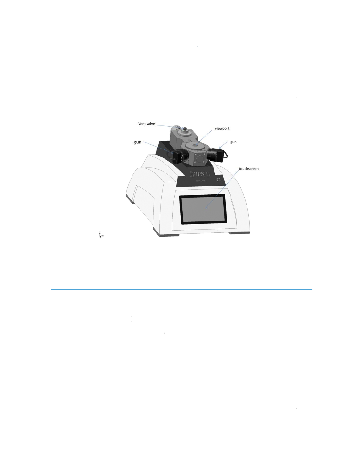
Figure 1-1 PIPS II, basic system, front view................................................. 17
Figure 1-2 Work chamber, top view............................................................... 20
Figure 1-3 Work chamber, cross-section view............................................... 21
Figure 1-4 Vacuum system............................................................................. 22
Figure 1-5 Gas-control system...................................................................... 23
Figure 2-1 View of connections on rear of cabinet........................................ 28
Figure 2-2 Camera system mount onto the PIPS II. ...................................... 29
Figure 2-3 Microscope front to back alignment. ............................................ 32
Figure 2-4 Microscope left to right alignment................................................ 33
Figure 3-1 Milling page.................................................................................. 34
Figure 3-2 Setting the milling duration........................................................... 35
Figure 3-3 Setting the modulation mode. ....................................................... 36
Figure 3-4 Setting the language..................................................................... 37
Figure 3-5 Recipes page.................................................................................. 38
Figure 3-6 Status bar, showing a recipe is running......................................... 38
Figure 3-7 Status bar, showing a recipe is completed successfully................ 39
Figure 3-8 Edit recipe page............................................................................. 40
Figure 3-9 Adding a recipe step...................................................................... 41
Figure 3-10. Deleting a recipe step................................................................. 41
Figure 3-11 Copying a recipe. ........................................................................ 42
Figure 3-12 Creating a new recipe: enter the name........................................ 42
Figure 3-13 Alignment page........................................................................... 43
Figure 3-14 Camera page................................................................................ 44
Figure 3-15. Viewing page. ............................................................................ 45
Figure 3-16 General Settings page.................................................................. 46
Figure 3-17 Setting the gas inlet used for the guns........................................ 46
Figure 3-18 Choosing the calibration table used for the Argon gas inlet...... 47
Figure 3-19. Milling sectors........................................................................... 48
Figure 3-20 Heaters settings page................................................................... 49
Figure 3-21 Auto-terminator page.................................................................. 49
Figure 3-22 Gas flow calibration.................................................................... 50
Figure 3-23 Motorized guns calibration. ........................................................ 51
Figure 3-24 Properly aligned stage in the Home position. ............................. 52
Figure 3-25 Stage home position calibration.................................................. 52
Figure 3-26 Temperature sensor calibration.................................................. 53
Figure 3-27 Pressure calibration..................................................................... 53
Figure 3-28 Foreline gauge calibration........................................................... 54
Figure 3-29 Cold Cathode gauge calibration................................................. 54
Figure 3-30. Vacuum page.............................................................................. 55
Figure 3-31 Gun Readings.............................................................................. 56
Figure 3-32 Gun Tilt page............................................................................... 57
Figure 3-33 Network page.............................................................................. 57

13
PIPS II Owners Manual and Users Guide
Figure 3-34 Software maintenance page......................................................... 58
Figure 3-35. Software configuration page...................................................... 59
Figure 3-36 Clock page................................................................................... 59
Figure 3-37 Milling page................................................................................ 60
Figure 3-38 Lowering the stage...................................................................... 62
Figure 3-39 Specimen mount in raised and working positions....................... 62
Figure 3-40 Camera page................................................................................ 63
Figure 3-41 Viewing page. ............................................................................ 64
Figure 3-42 Specimen mount raised and in the Home position...................... 65
Figure 3-43 x-y alignment, steps 7 (left) and 8 (right). .................................. 67
Figure 3-44 x-y alignment, steps 10 (left) and 11 (right). .............................. 68
Figure 3-45 x-y alignment, step 12................................................................. 68
Figure 3-46 x-y alignment, steps 14 (left) and 15 (right). .............................. 69
Figure 3-47 Operating characteristics of the PIG........................................... 70
Figure 3-48 X and Z-alignment device screws............................................... 72
Figure 3-49 Alignment ellipse observed in the beam..................................... 73
Figure 3-50 Gun knob with gun alignment knobs installed........................... 75
Figure 3-51 Modulation modes....................................................................... 77
Figure 3-52 Beam modulation........................................................................ 77
Figure 4-1 Gatan model 601 ultrasonic cutting tool....................................... 79
Figure 4-2 Gatan model 659.00001 disk punch.............................................. 80
Figure 4-3 Gatan model 623 disk grinder....................................................... 81
Figure 4-4 Disk grinding: initial and final...................................................... 81
Figure 4-5 Sample disk after dimple grinding (not to scale).......................... 81
Figure 4-6 Gatan model 656 dimple grinder................................................... 82
Figure 4-7 Specimen disc geometry. .............................................................. 84
Figure 4-8 Cross section specimen preparation.............................................. 86
Figure 4-9 Cross section specimen preparation.............................................. 87
Figure 4-10 Cross section specimen preparation............................................ 88
Figure 4-11 DuoPosts, glue type and clamp type........................................... 89
Figure 4-12 Clamp-type post and loading dock.............................................. 89
Figure 4-13 Mounting a sample, steps 1 and 2............................................... 91
Figure 4-14 Mounting a sample, Steps 4 and 5. ............................................. 91
Figure 4-15 Mounting a sample, step 8. ......................................................... 92
Figure 4-16 Graphite holder............................................................................ 93
Figure 4-17 Graphite holder loading dock...................................................... 93
Figure 5-1 Viewing port and o-rings. ............................................................. 99
Figure 5-2 Specimen mount removal............................................................ 103
Figure 5-3 Specimen-mount and window assembly..................................... 103
Figure 5-4 Cold-cathode gauge tube............................................................. 105
Figure 5-5 Cleaning the shutter..................................................................... 107
Figure 5-6. Removal and disassembly of ion guns....................................... 109
Figure 5-7 Ion source and magnet assembly................................................. 110
Figure 5-8 Removal of anode assembly and anode cup insulator. .............. 111
Figure 5-9 Removing anode cup assembly/front pole piece........................ 111
Figure 5-10 Focus electrode assembly......................................................... 117

14
PIPS II Owners Manual and Users Guide
Figure 5-11 Cover removal.......................................................................... 118
Figure 5-12 Molecular drag pump removal................................................. 120
Figure 5-13 Shutter servicing........................................................................ 123
Figure 5-14 Motor Drive Removal............................................................... 124
Figure 5-15 Replacing the encoder.............................................................. 126
Figure 5-16 Sample mount removal. ........................................................... 127
Figure 5-17 Whisperlok assembly............................................................... 129
Figure 5-18 checking the specimen height. .................................................. 132
Figure 5-19 Correct beam angle setting........................................................ 133
Figure 5-20 Sample height adjustment......................................................... 134
Figure 5-21 Gas manifold assembly............................................................ 135
Figure 5-22 MFC removal. Unplugging the power/signal cable from the
MFC.............................................................................................................. 138
Figure 5-23 MFC removal. Loosening the M3 screw that secures the MFC.
....................................................................................................................... 138
Figure 5-24 Touch display assembly........................................................... 140
Figure 5-25 Connections for touch display.................................................. 140
Figure 5-26 HVPS location.......................................................................... 141
Figure 5-27 Removing cables from the I/O PCA. ....................................... 142
Figure 5-28 PCA assembly.......................................................................... 143
Figure 5-29 PCA connector locations and associated cable part numbers.. 144
Figure 7-1 System with Cold Stage installed............................................... 149
Figure 7-2 Settings Page............................................................................... 152
Figure 7-3 Sample and cold conductor temperature over time..................... 154
Figure 7-4 Sample and cold conductor temperature over time..................... 155
Figure 7-5 Interior chamber showing the cold conductor with new brushes.156
Figure 7-6 Open chamber showing access to cold stage. ............................. 158
Figure 7-7. Dewar Assembly installed in manifold..................................... 159
Figure 7-8 Autoterminator sensor top view.................................................. 161
Figure 7-9 Autoterminator shown in working position................................ 162
Figure 7-10 Autoterminator page.................................................................. 163
Figure 7-11 System with digital zoom microscope. .................................... 164
Figure 7-12 DM environment....................................................................... 165
Figure 7-13 DM open image series............................................................... 167
Figure 7-14 DM standard tools..................................................................... 168
Figure 7-15 DM main menu. ........................................................................ 169
Figure 7-16 DM Histogram Window............................................................ 175
Figure 7-17 DM ROI menu........................................................................... 175
Figure 7-18 DM Slice tool............................................................................ 178
Figure 7-19 DM Slice player. ....................................................................... 178
Figure 7-20 DM video compression............................................................. 179
Figure 7-21 DM Ion Polish Control window................................................ 179
Figure 7-22 DM Ion Polish Camera Control window. ................................ 180
Figure 7-23 DM PIPS II record options window.......................................... 181
Figure 7-24 Camera page.............................................................................. 182
Figure 7-25 PIPS II with motorized gun tilt................................................ 183

15
PIPS II Owners Manual and Users Guide
Figure 7-26 Gun tilt settings......................................................................... 184
Figure 7-27 Motorized gun assemblies........................................................ 185
Figure 7-28 Gun tilt maintenance screen..................................................... 186
Figure 7-29 Gun tilt calibration screen........................................................ 186

16
PIPS II Owners Manual and Users Guide
List of Tables
Table 1 Polishing wheel diameter versus dimple depth.................................. 82
Table 2 Optimum initial specimen disc thickness.......................................... 83
Table 3 Typical Milling rates.......................................................................... 96
Table 4 Bulk/rim thickness vs. minimum milling angle................................ 96
Table 5 PIPS II milling parameters................................................................ 97
Table 6 Maintenance Operations.................................................................... 98
PIPS II
O
1.1
.
1
1
O
wners Ma
n
T
h
be
e
x
fo
F
i
.
Fea
.1.1. Dual
I
o
(
P
a
n
w
i
c
a
s
o
s
p
a
n
a
v
.1.2. Opti
m
T
h
a
n
ual and Us
e
h
e Model 6
9
e
nch-top sy
s
x
ceptionally
r PIPS II so
f
gure 1-1 PI
P
tures o
f
Ion Sourc
n polishing
P
IGs). The o
p
n
d both hav
e
i
thin this ra
n
a
pable of ve
r
o
that the x-
p
ecimen. T
h
n
gles in a r
e
v
ailable as a
n
m
um Gun
D
h
e gun’s io
n
result, gun
e
rs Guide
1.
9
5 Precisio
n
s
tem desig
n
large, clean
,
f
tware versi
o
P
S II, basic
s
f
the Pr
e
e
is done b
y
p
erating an
g
e
the ability
n
ge. The PI
G
r
y high thin
n
and z-align
h
ese feature
s
e
asonably s
h
n
optional f
e
D
esign
n
optics has
v
maintenanc
e
Ove
rv
n
Ion Polis
h
n
ed to prod
u
,
electron-tr
a
o
n 1.6.
s
ystem, fron
t
e
cision I
y
two vari
a
g
le of each
g
to center t
h
G
s incorpo
r
n
ing rates.
E
m
ent drives
s
make it
p
h
ort time.
M
e
ature.
v
irtually eli
m
e
is reduce
d
r
view
h
ing Syste
m
u
ce high-q
u
a
nsparent ar
t
view.
I
on Poli
s
a
ble-angle,
m
g
un, ± 10°, i
h
e beam on
t
r
ate powerf
u
E
ach gun is
can be use
d
p
ossible to
t
M
otorized o
p
m
inated cat
h
d
, specimen
m
(PIPS II
™
u
ality TEM
eas. This m
a
s
hing S
y
m
iniature P
s independe
t
o the speci
m
u
l rare-earth
mounted in
d
to center
t
t
hin speci
m
p
eration of
b
h
ode-apertu
r
contaminat
™
) is a co
m
specimens
a
nual was
w
y
stem
enning ion
nt of one a
n
m
en at any
magnets a
n
a universal
t
he beams
o
m
ens at ver
y
b
eam tilt an
g
r
e erosion a
n
ion from t
h
17
m
pact,
with
w
ritten
guns
n
other
angle
n
d are
joint
o
n the
y
low
g
le is
n
d, as
h
e ion

18
PIPS II Owners Manual and Users Guide
guns is minimized, and gun consumables have been eliminated. The new
focus electrodes in each gun have improved the low energy spot size, keeping
the spot size approximately constant across all beam energies. This results in
dramatically faster milling rates at low energy, such that it is now practical to
mill to perforation at energies as low as 100 eV.
1.1.3. Gas Flow Optimization
The optimum gas flow for all beam energies is calibrated at the factory, and
may be selected by using the automatic gas flow option. The gas flow of each
gun may also be set manually.
1.1.4. Compact Vacuum System
Specimen contamination is reduced with an oil-free vacuum system consisting
of a molecular drag pump (MDP) backed by a 2-stage diaphragm pump (DP).
Additionally, a liquid-nitrogen trap is available to further reduce contaminants
and water vapor.
1.1.5. Touch-screen Interface
Operation of the system is controlled by the user via a touch-screen interface,
which is customer selectable between several languages.
1.1.6. Versatile Sample Holders
The Gatan specimen post, for single-sided milling, and the DuoPost, for
double-sided milling, eliminate transfer of material onto the specimen by
secondary sputtering from the specimen platform and provide excellent
thermal contact with the specimen to prevent specimen overheating. Lastly,
both specimen posts allow the specimen to have an unobstructed view of the
ion beam and thus ion polishing can be performed at angles approaching 0°.
In order to allow for centering the thin section at the rotation axis the sample
mount includes a manual x-y stage. This allows the user to compensate for a
sample that is mounted off-axis in the post.
1.1.7. Stereo Microscope
An optional optical stereo microscope is used to inspect the specimen in its
working position at any time during the thinning process to achieve very
precise control over the final stage of specimen thinning. This feature is
especially important for insulators and semi-conductors since these materials
are transparent to light and the interference-fringe technique can be used to
control the final specimen thickness in the region of interest to an accuracy of
about ±10 nm.

19
PIPS II Owners Manual and Users Guide
1.1.8. Digital Zoom Microscope System
The Digital Zoom Microscope is a system option. This system uses a digital
camera connected to an external PC. The camera is mounted on the system
and allows for in-situ observation of the sample. In addition, the supporting
software allows for manual/automated acquisition of images, typically one
automated image per rotation. The external PC can also be used for remote
control of the PIPS II system, via remote desktop type software.
1.1.9. Autoterminator
This can be provided as an optional feature and uses the amount of light
transmitted through the sample. Milling is stopped when this reaches a
previously set value.
1.1.10. WhisperlokTM Stage
Quick specimen exchange (<30 sec) is achieved using a miniaturized version
of Gatan’s pneumatically controlled Whisperlok™. The specimen can be
easily transferred and viewed at frequent intervals during the final moments of
the thinning process.
20
PIPS II Owners Manual and Users Guide
1.2. Main Work Chamber
Figure 1-2 is a top view of the PIPS II main Work Chamber. The figure shows
the right and left PIGs. The Airlock cover is removed to reveal the main
Airlock O-ring and a top view of the specimen mount.
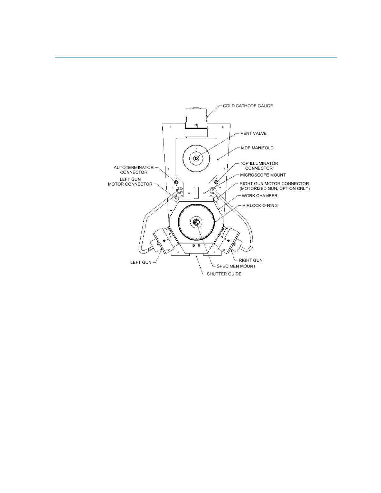
Figure 1-2 Work chamber, top view.
Figure 1-3 is a cross-sectional view through the main Work Chamber of the
PIPS II. The Airlock cover is in place with the specimen in its working
position at the center of the Chamber.
Specimens are mounted on posts that plug into the specimen mount and can
be milled on both surfaces with proper orientation of the PIGs. One of the
PIGs is shown inclined at a positive angle (+10°) to the horizontal (beam
incident to the top surface of sample). By simply grasping the gun knob and
rotating it, the gun angle can be reduced down through 0° continuing on to a
negative angle (-10°, beam incident to the bottom surface of sample).
The Shutter is shown in its inserted position, which prevents sputtered
material from depositing on the specimen Viewing Port.
Table of contents
Other Gatan Ultrasonic Jewelry Cleaner manuals


