Gates MOBILE CRIMP 4-20 Installation manual

1
MOBILE CRIMP® 4-20
DIGITAL DIAL CONTROL
SAFETY AND OPERATING MANUAL

2
Shop Air Pump
Prod. No.: 7481-0002, Part No.: 77820
Weight: 10 lbs.
1/4 H.P. 12 Volt DC Pump
Prod. No.: 7481-0037, Part No.: 77439
Weight: 20.5 lbs.
1/2 H.P. 115 Volt AC Pump
Prod. No.: 7481-0034, Part No.:77441
Weight: 32 lbs.
Hand Pump
Prod. No.: 7481-0006, Part No.: 77821
Weight: 25.6 lbs.
1-1/2 H.P. 115 Volt AC Pump
Prod. No. 7481-0035
Weight: 108 lbs.
Carefully read and understand all the following warnings before operating this crimper.
WARNING!
An incorrect hose assembly can rupture or blow apart in use, resulting in serious injury, death, or
property damage. REMEMBER: Others depend on you to make correct assemblies.
FOR SAFETY’S SAKE USE THIS MACHINE ONLY IF YOU:
1. Receive hands-on TRAINING with this Gates crimper and assemblies.
2. Follow current GATES OPERATING MANUAL and CRIMP DATA for the MoblieCrimp®4-20.
3. Use only NEW (UNUSED) GATES hose and ttings.
4. Wear SAFETY GLASSES.
5. KEEP HANDS CLEAR of moving parts.
PUMP SPECIFICATIONS
All pumps maximum rated working pressure: 10,000 psi
DIGITAL DIAL CONTROL
Prod. No.: 7480-0051, Part No.: 77421
Dimensions: 12 1/4" wide x 6 1/4" deep x 19 1/2" high
Weight: 57 lbs. (with stand)

Contents
Identication List..........................................................................................................4
Setup...........................................................................................................................5-7
Calibration Procedure...................................................................................................8
Hose Preparation........................................................................................................9-10
Operating Instructions............................................................................................11-14
Measuring and Adjusting Diameter............................................................................15
Maintenance.................................................................................................................16
Troubleshooting...........................................................................................................17
Replacement Parts List.......................................................................................18-19
Serial No. ____________________
(Located on front top of cylinder)
Date of Purchase ____________
3

.05 ALLEN WRENCH
CLAMPS
STAND
MOLYKOTE AND BRUSH
LITERATURE PACKET
HOSE ASSEMBLY
PRESSURE PLATE
DIE
CRIMPER
MAGNET
CALIPERS
4
IDENTIFICATION LIST MOBILE CRIMP 4-20 SAFETY AND OPERATING MANUAL

UNPACK CARTON
Remove crimper, pressure plate, nylon-covered hose
assembly. literature envelope, magnet, .05 Allen
wrench, and Molykote lubricant from shipping carton.
Locate the serial number assigned to the crimper on
the top front of the cylinder and record on page one
for future reference.
ATTACH CRIMPER TO THE STAND
Place crimper on at, well- supported surface (such
as the top of a workbench or the bed of a service
vehicle) with the handle to the right.
Remove two knobs, at washers, and spacer from
the crimper pivot bolts.
Slide the two halves of the stand together and
attach to the crimper at the pivot bolts.
Replace spacer, at washer, and knobs. Do no
tighten knobs.
Lift crimper and allow stand to swing down onto
the surface. Tighten knobs.
LEFT SIDE
RIGHT SIDE
SPACER
1.
2.
SETUP
5
MOBILE CRIMP 4-20 SAFETY AND OPERATING MANUAL
FASTEN CRIMPER TO WORK SURFACE STATION
BEFORE USE (to avoid damage to machine or
personal injury because an unsecured machine
can fall).
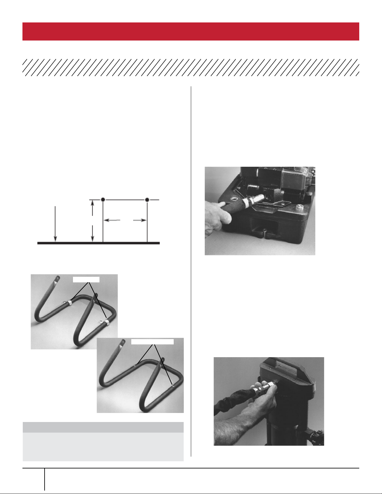
Position crimper so that mounting holes are
approximately 7” to 8” from the edge of the
work surface.
Mark the drilling location using the mounting holes
as a guide (see illustration below).
Drill two 5/16” diameter holes then use mountig
holes or clamps to fasten stand to work surface.
ATTACH PUMP TO CRIMPER
Place pump near crimper and connect hose
assembly to the pump port (3/8” NPT threads).
Pipesealant may be used to seal connection.
(Forbest connection, use Gates’ Quick Disconnect
couplings, G95311-0606 and G95321-0606,
sold separately.)
Connect opposite end to the adapter or crimper.
CHECK PUMP OIL LEVEL
Pump comes with oil in reservoir. Check proper oil
level per pump operating manual instructions or the
Maintenance section of this manual.
CONNECT PUMP TO POWER OUTLET
For 115V connection, plug power cord into a properly
grounded and rated circuit. For vehicle battery
connection, see pump operating manual.
EDGE OF
WORK
SURFACE
(2) 5/16" DIAMETER HOLES
7 1/2" 11"
Clamps
3. 4.
5.
To avoid damage to the machine ALWAYS fasten
the crimper to the work surface before you
attempt to crimp.
THINK SAFETY!
Mounting Holes
6.
6
SETUP MOBILE CRIMP 4-20 SAFETY AND OPERATING MANUAL
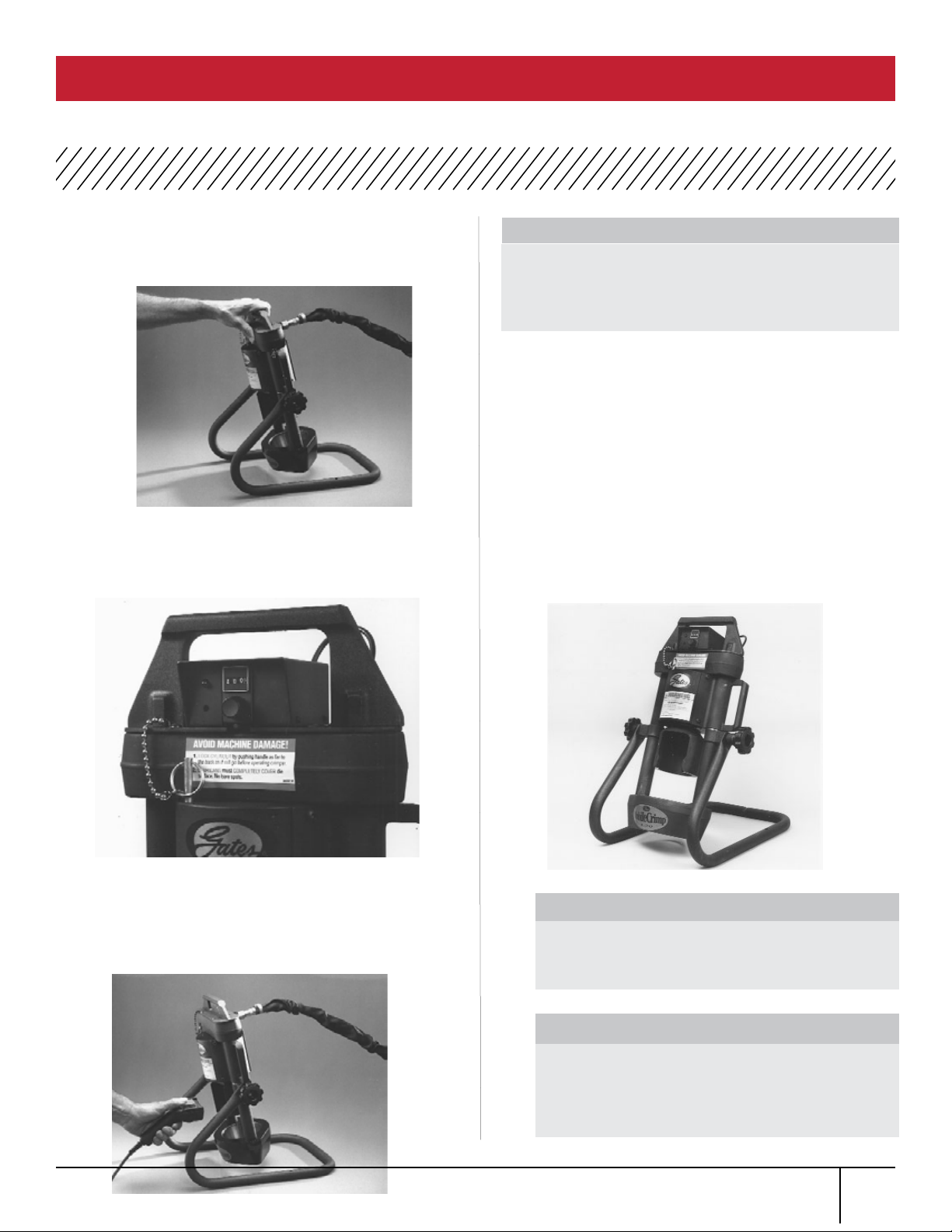
BLEED AIR FROM SYSTEM
Tilt crimper forward so adapter is at its highest point.
Turn the knob on the controller to a setting of 400,
which allows the ram to extend approximately 1”.
Turn pump on by pressing and holding the power
“on” switch, (see pump operating manual for switc
location) which extends the ram.
When the light comes on and buzzer sounds,
immediately release “on” switch allowing ram to
fully retract. NOTE: If light and buzzer are faint
do not work, the controller batteries may need
replacement. See “Maintenance” section of this
manual. Repeat a minimum of ve (5) times to bleed
air completely.
PLACE CRIMPER IN COMFORTABLE
WORKING POSITION
See photo below for suggested working
7. CAUTION
Keep away from all moving parts!
If bodily contact with a moving part occurs,
immediately release the pump power “on” switch.
IMPORTANT
Do not operate crimper in horizontal position
because dies will become unstable.
THINK SAFETY
NOTE: It’s a good idea to place a rubber mat on
the oor near the crimper to reduce the chance
of damaging a die if dropped and improve
operator comfort.
8.
7
SETUP MOBILE CRIMP 4-20 SAFETY AND OPERATING MANUAL

Before crimping a hose assembly, check calibration.
Calibration is the proper relationship between a
setting and the crimp diameter. It should be
checked at least monthly, possibly weekly or daily, if
crimper has been used heavily or abused. Mark the
drilling location using the mounting holes as a guide
(see illustration below).
Place the MC33 die set into the die cone and install
pressure plate.
Turn the knob to a setting of 245.
Insert an 8G MegaCrimp® coupling into the die set.
Complete the crimp.
Remove the coupling and measure the crimp
diameter, which should measure 1000” +/- .003”
To properly measure crimp diameter, refer to the
Measuring and Adjustment Diameter sections of
this manual.
If diameter is within range, no adjustment is
necessary. If the crimp diameter is not within this
ranger the crimper must be calibrated.
To get a larger or smaller number adjust accordingly
For every .001” change in crimp diameter, change
the setting by .002. For example, to increase the
crimp diameter by .002”, increase your setting
from 245-247.
Turn the knob to this new setting and crimp a new
coupling. After the correct diameter is achieved, pull
the plastic cap from the
Loosen the two set screws in the brass knob 1/4 to
1/2 turn using a .05” Allen wrench.
Turn the brass knob either clockwise or counter
clockwise to get the setting back to 245.
Tighten the set screws
and replace the plastic
cap. Crimper is
now calibrated.
Note: Rotating the knob on front of switch box
clockwise will increase the number; counter
clockwise will decrease the number. When
changing the setting, always moveto a higher
number then down to the desired setting. (Ex:
To change from 200- 245, move dial up to 300
then down to 245.)
1. 6.
CALIBRATION PROCEDURE MOBILE CRIMP 4-20 SAFETY AND OPERATING MANUAL
2.
3.
4.
5.
7.
8.
9.
10.
8

CAUTION
A new hose and end ttings must be used when
building a hose assembly. Re-using any components will
seriously affect performance and could result in serious
injury or property damage.
Cut hose to desired length.
Using Gates Crimp Data Chart (#35019 (Ind), 428
7365 (Auto)), select the correct coupling or visit our
website to download our electronic program at
ecrimp.gates.com.
Place a visible mark on hose cover at the insertion
length shown on the crimp data chart
Insert coupling into the hose until the mark lines up
with the end of the coupling ferrule.
Hose and coupling are now ready for crimping.
1.
4.
HOSE PREPARATION MOBILE CRIMP 4-20 SAFETY AND OPERATING MANUAL
2.
3. 5.
MEGACRIMP® PRE-ASSEMBLED COUPLINGS
9

A new hose and end ttings (stem/ferrule) must be
used when building a hose assembly. Re-using any
components will seriously affect performance and could
result in serious injury or damage.
Cut hose to desired length.
Using Gates crimp data chart (#35019 (Ind),
428-7365 (Auto)), select the correct coupling or visit
our website to download our electronic program at
ecrimp.gates.com.
Place ferrule over the end of the hose.
Lubricate the rst two or three serrations on stem
with lightweight oil (SAE 10W).
Clamp stem in vise on hex portion, and push hose
onto stem.
Hose should be ush against stem shoulder (see
cutaway drawing below).
Hose and coupling are now ready for crimping.
HOSE PREPARATION MOBILE CRIMP 4-20 SAFETY AND OPERATING MANUAL
1.
2.
6.
GLOBAL SPIRALTM TWO-PIECE COUPLINGS
CAUTION
3.
4.
5.
10

Hydraulic Hose Crimp Data MC4-20 Digital Dial
and Positive Stop Crimpers
DIE SET
THINK SAFETY
IMPORTANT NOTE: Lubricants should be reapplied
to metal-to-metal sliding surfaces whenever the
surface becomes shiny. Failure to do this reduces
the life of the dies and cone. Excessive wear on
these components produces poorly performing hose
assemblies that could blow apart and
result in injury.
*Use only Gates Molykote lube for proper operation or
Gates- recommended grease.
SELECT CORRECT DIE SET
Using Gates Crimp Data Chart (#35019 (Ind), 428
7365 (Auto)) or ECrimp, select correct die set for the
hose and coupling being crimped.
LUBRICATE AND LOAD DIE
Swing cylinder to “die loading” position.
Apply thin layer of Molykote* lube to the inside
surface of the die cone. Re-apply lube whenever
surface become shiny.
Using the magnet, place the die set into the
die cone.
Remove magnet by lifting the “T” handle, making
sure the top of the die ngers are even.
Apply a thin layer of Molykote lube to the top of the
die set.
1.
OPERATING INSTRUCTIONS MOBILE CRIMP 4-20 SAFETY AND OPERATING MANUAL
2.
11
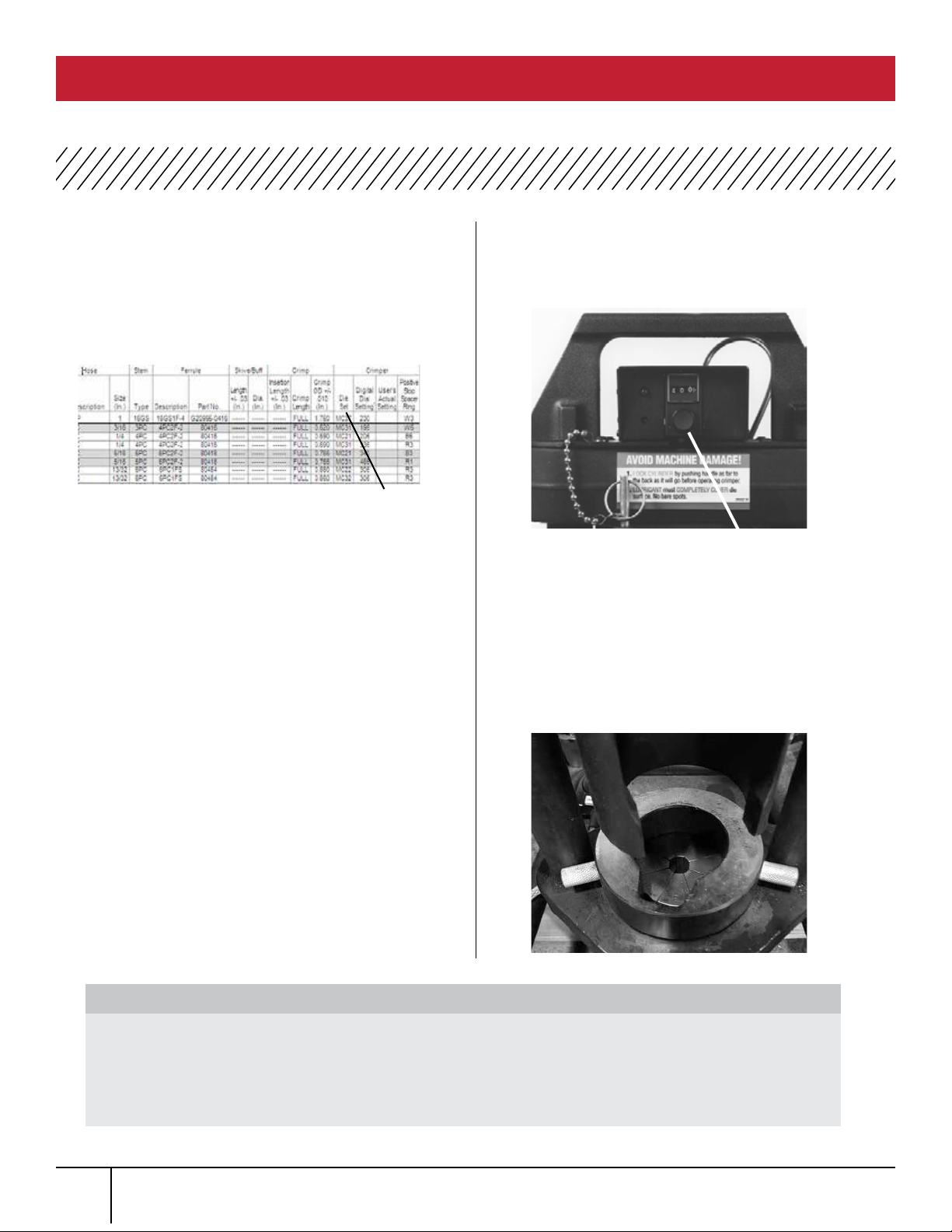
SELECT CORRECT SETTING
Using Gates Crimp Data Chart (#35019 (Ind), 428
7365 (Auto)) or ECrimp, select correct die set for the
hose and coupling being crimped.
Settings are appropriate and may need to be
ajusted. See Measuring and Adjusting the
Crimp Diameter.
DIAL IN SETTING AND INSTALL PRESSURE PLATE
Turn the knob on the controller to the
selected timing.
If crimping multiple assemblies, move the
locking switch to the right to hold the setting.
Moving switch to the left allows the setting to
be changed.
Place the pressure plate onto the die set.
THINK SAFETY
IMPORTANT NOTE: All setting are approximate! Matching tolerances exist for each crimper, die set and
supporting piece of equipment which will affect your actual setting. Always check the crimp diameter to
ensure that it is within the published limits. Record your actual crimper setting to achieve the specied
crimp diameter for future use. Failure to heed this message could result in improperly made assemblies,
blowing the hose out of the ttings at high pressure, and risk of re or serious injury.
LOCKING SWITCH
OPERATING INSTRUCTIONS MOBILE CRIMP 4-20 SAFETY AND OPERATING MANUAL
1. 4.
Hydraulic Hose Crimp Data MC4-20 Digital Dial
and Positive Stop Crimpers
SETTING
12
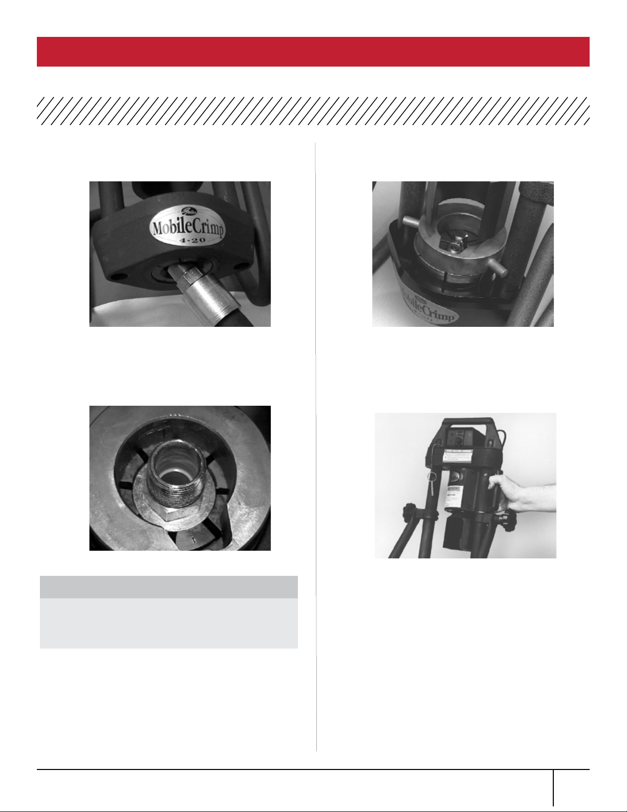
INSERT HOSE ASSEMBLY from the bottom of the die
cone up through the die set.
Locate the top of the ferrule approximately 1/16”
below the top of the die set.
When crimping bent tube and block-style couplings,
keep thread end aligned with notch in pressure plate.
SWING CYLINDER INTO CRIMPING POSITION
Using the handle, swing cylinder toward you and lock
into place with lock pin.
IMPORTANT
For GS couplings, make sure the top of the
ferrule rests against the hex or round shoulder
of the coupling.
5.
OPERATING INSTRUCTIONS MOBILE CRIMP 4-20 SAFETY AND OPERATING MANUAL
6.
13

Make sure cylinder is locked into position by placing
lock pin into hole on top of cylinder.
BEGIN THE CRIMP
Start by steadying hose with one hand while
pressing and holding the power “on” switch
withthe other hand, which extends the ram
(seepump operation manual for switch location).
When light comes on and buzzer sounds,
IMMEDIATELY release the power “on” switch.
NOTE: If light and buzzer become faint or do not
work, the controller batteries may need replacement.
See Maintenance Section.
REMOVE HOSE ASSEMBLY
While holding hose, lightly lift bottom of die set
to release hose assembly.
Remove hose assembly.
Serious injury and/ or crimper damage can result
if the cylinder is not locked in its
crimp position.
LOCK PIN
Keep away from all moving parts! If bodily contact
with a moving part occurs, immediately release the
pump power “on” switch.
CAUTION
INCORRECT CORRECT
OPERATING INSTRUCTIONS MOBILE CRIMP 4-20 SAFETY AND OPERATING MANUAL
7.
8.
IMPORTANT
14
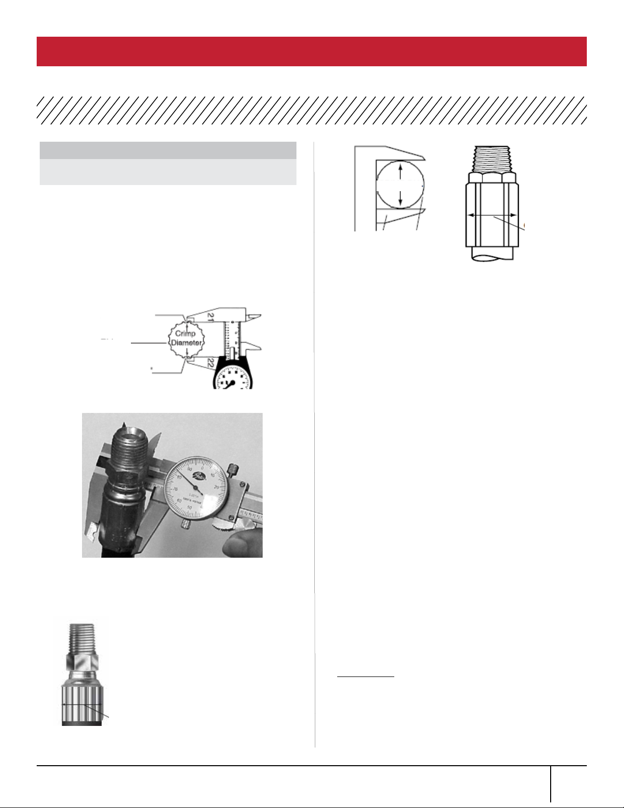
MEASURE THE CRIMP DIAMETER
When using 21 and 22 dies, measure half way
between ridges (Fig. 1). To be sure
crimp diameter is being properly measured, mark a
crimp at. Beginning with that at, count 9 ats to
get the diameter. Be sure caliper blades DO NOT
touch ridges. (See photo 1.)
Measure halfway between the ends of crimped portion
of the ferrule (Fig. 2).
Measure halfway down the crimped portion of the
ferrule (Sketch 2).
CHECK CRIMP DIAMETER
The measured crimp diameter must be within 0.010”
of the published crimp diameter. If not, the hose
assembly cannot be used, and adjustment will
be required.
ADJUST THE CRIMP DIAMETER (IF NECESSARY
Check top of die set and the surfaces of the
pressure plate for any debris (metal chips, dirt,
etc.). Debris may cause some variation
in crimpdiameter.
If necessary, clean the surfaces and lightly lubricate
with Molykote.
If the machine is properly calibrated, a slight
adjustment to the crimp setting can be made.
To get a smaller crimp diameter, change the setting
to a smaller number.
To get a larger crimp diameter change the setting to
a larger number.
For every .001” change in crimp diameter, change
the setting by 002. For example, to increase the
crimp diameter by .002”, increase your setting from
245 to 247.
After the correct diameter is achieved, record
thisnew setting on your crimp data chart for
futurereference.
MULTIPLE CRIMPS
When crimping multiple assemblies check every
tenth crimp to ensure diameter is within acceptable
range (+/- 0.010”).
NOTE: For Crimping with the 20G and the
MC38 Die Set you will need the 20G/MC38
Pressure Plate (Product No. 7482-1078,
Part No. 78046)
NOTE:
DO NOT measure on top of part
number stamps.
Crimp Flat “1”
FIGURE 1
Crimp Flat “9”
Ridges
When NOT using 21 and 22
dies use Gates dial calipers
(Product No. 7369-0322,
Part No. 78215) which are
notched to clear ridges,
measure halfway between
ridges (Sketch 1). Be sure
caliper ngers DO NOT
touch ridges or part number
stamps. (See Photo 1)
SKETCH 2
PHOTO 1
Crimp
Diameter
FIGURE 2
Crimp
Diameter
Crimp Dia.
Ridges
Caliper
SKETCH 1
1.
MEASURING AND ADJUSTING DIAMETER MOBILE CRIMP 4-20 SAFETY AND OPERATING MANUAL
2.
3.
4.
15

This crimper requires minimal maintenance.
However, the following practices are recommended to
ensure maximum reliability and service.
LUBRICATE
Using the small brush and Molykote, apply a
light coat to the inside surface of the die cone
whenever it becomes shiny.
CHECK OIL LEVEL
Check the hydraulic oil level in the pump reservoir
after each 10 hours of use (see pump operations
manual for instructions).
The oil is more than 1/2” below the top, add a high
grade hydraulic oil, such as Enerpac Oil, until
within 1/2” of the top of the reservoir.
CHANGE THE OIL
NOTE: Frequency depends on the pump’s general
working conditions, severity of use, and overall
cleanliness.
For general shop conditions, change oil every 300
hours. For eld/mobile conditions, more frequent
changes are required.
Drain, clean, and rell the reservoir per pump
operating instructions with a high-grade hydraulic
oil, such as Mobil DTE 25 until within 1/2” of the top
of the reservoir.
IMPACT DIE SETS AND PRESSURE PLATE
Periodically inspect the surfaces of die sets and
pressure plate for debris (metal chips, dirt, etc.)
or damage.
If debris is present, clean and lightly lubricate. If
damaged, replacement is required (see parts list for
ordering information).
Inspect the die links, springs, and shoulder
screws monthly to see if they are broken, cracked,
or missing. These conditions may affect crimp quality
Replace if necessary.
INSPECT HOSE ASSEMBLY
Inspect hose assembly connecting the crimper and
pump monthly (more often with severe use).
Check nylon sleeve for cuts or abrasions. If sleeve
is damaged, check hose for damage. If hose
has signs of damage, replace immediately. A
damaged hose may rupture and cause serious injury.
If hydraulic oil is present on the hose assembly,
serious damage may exist. Replace immediately.
BATTERY REPLACEMENT
If light and buzzer become faint or do not work,
batteries may need replacement. The controller uses
AAA batteries. Remove the two screws located on the
lower left side of the controller. Remove the side
cover and the batteries from their holder.
Replace the batteries and position as shown on
holder. Replace and secure the side cover.
MAINTENANCE MOBILE CRIMP 4-20 SAFETY AND OPERATING MANUAL
16

All equipment is tested for proper performance before it is shipped from the factory. However, if you experience any
difculties, check the list below to help restore equipment to proper operating standards.
PROBLEM CORRECTION
Ram will not fully extend Check hydraulic oil level in pump reservoir.
Hydraulic oil temperature must be withing +40 anD
+120 degrees F.
Ram will not retract Unplug pump from electrical outlet. (WARNING:
pump must be unplugged to avoid injury.)
Slowly and carefully loosen hose at pump.
Be prepared to catch oil as it escapes. If ram
retracts, pump valve may be stuck or
need replacement.
Pump motor will not start. Check electrical connections.
Setting will not change. Lock switch may be engaged. Move switch to
the left.
Light and buzzer do not work. Replace the controller batteries. See
maintenance section.
Replace controller.
TROUBLESHOOTING MOBILE CRIMP 4-20 SAFETY AND OPERATING MANUAL
17

Item
No.
Prod. No. Part No. Description Quantity
1 7482-1036 78437 Pusher 1
2 7482-1005 78455 Stand 1
3 7482-1190 78425 Retaining Ring Kit 1
4 7482-1163 78420 Handle 1
5 7482-1109 78459 Stand Clamp 2
6 7482-1064 78421 Lock Pin 1
7 7482-1165 78422 Chain, Lock Pin 1
8 7482-1015 78465 Pressure Plate 1
9 7482-1041 78440 Seal Kit 1
10 7482-1171 78397 Digital Dial Controller Assembly 1
12 7482-1012 78462 Pivot Knob 2
13 7482-1097 78442 Knob, Digital Dial 1
14 - 35032-D Cone Plate Decal 1
15 - 35032-G Gates Decal 1
16 - 35032-DA Cylinder Warning Label 1
17 - 35032-DB Top Plate Warning Label 1
18 - 35032-W Machine Damage Warning Label 1
19 - - Button Head Cap Screw, 1/4-20 x 3/8 4
20 - - Socket Head Cap Screw, 1/4-20 x 3/4 4
STANDARD ITEMS
18
REPLACEMENT PARTS MOBILE CRIMP 4-20 SAFETY AND OPERATING MANUAL

Item No. Prod. No. Part No. Description Quantity
21 - - Socket Head Cap Screw 3/8-16 x 1-1/4 1
22 - - Socket Head Cap Screw 3/8-16 x 3/4 2
23 - - Button Head Cap Screw, 10-32UNF x
3/8
1
24 7253-0216 86319 Adapter, 6MP-6FPX90, Gates 1
25 7482-1006 78456 Pivot Spacer 1
26 7482-1172 78398 Cover, DD Controller 1
* 7482-1017 78467 Hose Assembly, 4 ft. 1
* 7482-1155 78429 Hose Assembly, 8 ft. 1
STANDARD ITEMS
Prod. No. Part No. Description Quantity
7482-1131 78468 MC 31 Die Set Assembly -
7482-1132 78469 MC 32 Die Set Assembly -
7482-1133 78470 MC 33 Die Set Assembly -
7482-1134 78471 MC 34 Die Set Assembly -
7482-1135 78472 MC 35 Die Set Assembly -
7482-1036 78473 MC 36 Die Set Assembly -
7482-1137 78 474 MC 37 Die Set Assembly -
7482-1138 78475 MC 38 Die Set Assembly -
7482-1139 78476 MC 39 Die Set Assembly -
7482-1140 78431 MC40 (-6AC) Die Set Assembly -
7482-1141 78432 MC41 (-8AC) Die Set Assembly -
7482-1142 78433 MC42 (-10AC) Die Set Assembly -
7482-1143 78434 MC43 (-12AC) Die Set Assembly -
7482-1144 78452 MC44 (PS) Die Set Assembly -
7482-1145 78497 MC45 (GF) Die Set Assembly -
7483-1147 78396 Die Set, Spring 8
7483-1148 78397 Die Set, Link 8
7483-1149 78398 Die Set, Shoulder Screw 8
7482-1220 78558 Die Set 21 -
7482-1221 78559 Die Set 22 -
7252-8831-5 G95311-0606 Male Quick Connect Coupler -
OPTIONAL ITEMS
19
REPLACEMENT PARTS MOBILE CRIMP 4-20 SAFETY AND OPERATING MANUAL

20
NOTES MOBILE CRIMP 4-20 SAFETY AND OPERATING MANUAL
Table of contents
Popular Control Unit manuals by other brands


 ADDENDUM 8505017 REV B... manual")
TJERNLUND
TJERNLUND UC1 UNIVERSAL CONTROL (VERSION X.06) ADDENDUM 8505017 REV B... manual

Eaton
Eaton P1 I2 Series Instruction leaflet

Flo-Tite
Flo-Tite F150 Installation operation & maintenance

TIL
TIL T3014 RF user guide

RJG
RJG Lynx ID7-M-SEQ product manual

Philips
Philips basicPalette II Installation and setup gude