manuals.online logo
Brands
  1. Home
  2. •
  3. Brands
  4. •
  5. ElMod
  6. •
  7. Control Unit
  8. •
  9. ElMod ThinkTank Pro Assembly instructions

ElMod ThinkTank Pro Assembly instructions

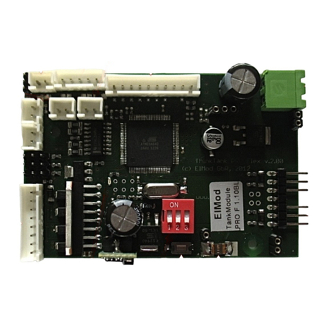
ThinkTank Tank Module PRO
Instructions for Assembly and Handling
Please read this document carefully!
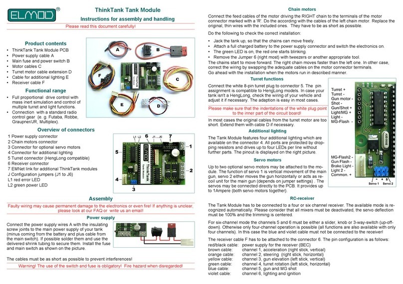
Product contents
•ThinkTank Tank Module PRO PCB
•ready to use power supply cable set
•motor connectors
•proportional receiver cable set
•two cables for additional light
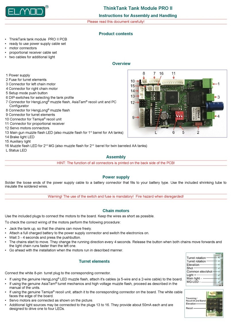
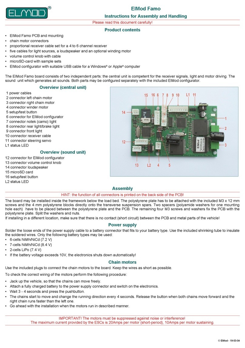
Overview of connectors
Power supply
2 Fuse for turret elements
3 Connector for left chain motor
4 Connector for right chain motor
5 Setup mode push button
6 DIP-switches for selecting the tank profile
7 Connector for HengLong muzzle flash, AsiaTam
recoil unit and PC Configurator
8 Connector for HengLong muzzle flash
9 Connector for turret elements
0 Connector for Tamiya recoil unit
Connector for proportional receiver
2 Servo motors connectors.
3 Main gun muzzle flash LED (also muzzle flash for st barrel for AA tanks)
4 Brake light LED
5 Auxiliary light
6 Muzzle flash LED for 2nd MG (also muzzle flash for 2nd barrel for twin barreled AA tanks)
7 EMNet interface for expansion boards
L Status LED
Assembly
HINT: the function of all connectors is printed on the back side of the PCB!
Power supply
Solder the loose ends of the power supply cable to a battery connector that fits to your battery
type. Use the included shrinking tube to insulate the soldered wires.
Warning! The use of the switch and fuse is mandatory! Fire hazard when disregarded!
hain motors
Use the included plugs to connect the motors to the board. Keep the wires as short as possible.
To check the correct wiring of the motors perform the following procedure:
•Jack the tank up, so that the chains can move freely.
•Attach a full charged battery to the power supply connector and switch the electronics on.
•Wait 3-4 seconds. Press and hold the pushbutton.
•The chains start to move and change their rotation direction every 3 seconds. Release the
button if both chains move forwards and the right chain runs faster than the left one. If this
constellation doesn't occur after 20 seconds, check and correct the wiring of the motors.
•Go ahead with the installation when the motors run in described manner.
Turret elements
Connect the white 8-pin turret plug to the corresponding connector.
•If using the genuine HengLong LED muzzle flash, attach it's cables (a
5-wire and a 2-wire cable) to the board.
•If using the genuine AsiaTam turret mechanics and high voltage
muzzle flash, proceed as described in the manual of the units.
•If using the genuine Tamiya(R) recoil unit, attach it to the correspon-
ding connector on the board. The white cable faces the edge of the
board.
•Servo motors are connected as shown on the picture.
•Additional light sources may be connected to the plugs 3 to 6.
They provide about 50mA each and are designed to drive one to four
LEDs.
hoosing the tank profile
The driving and function setup is determined by the position of the DIP switches. The Tank
Module ECO offers seven fixed and one user defined profile
German, WW2, plastic gearboxes US, WW2, metal gearboxes
German, WW2, metal gearboxes T-34
German, WW2, 3: reducted gearbox easy-to-drive tank
user defined
US, WW2, plastic gearboxes setup used by the ThinkTank Configurator
and PC Configurator
Status LED
The onboard LED shows the current status of the module
on Tank Module is in operational state
Short going out Stick movement detected
Fast blinking No valid signal from receiver*
Slow blinking Faulty communication with another module
*no connection to the sender or the transmission path between sender and receiver is disturbed.
Please check the wiring and the proper function of the RC radio and receiver. If necessary check
the operability of the RC equipment with a servo.
R receiver
The Tank Module ECO may be connected with four to eight channel receiver. The currently active
mode of operation is recognized automatically. Please consider that the radio must be setup
correctly (all mixers must be deactivated, the servo deflection must be 00% and the trimming is
centered)
If the channels five to eight are used, they must be equipped either as a slider, knob or 3-way-
switch (up-off-down). Otherwise only four-channel operation is possible (although mostly all
functions are also available with only four channels). The wires of unused channels may not be
connected to the receiver.
The receiver cable has to be attached to the receiver connector on the Tank Module. The wire
color pin assignment is as follows:
The TankModule electronics provides the power supply for the receiver (BEC, stabilized 5V DC)
via the red/black wires which are part of the proportional cable set.
h. ontrol 4-channel mode 5-channel mode 6-channel mode
1rechter Knüppel Acceleration Acceleration Acceleration
2Steering Steering Steering
3linker Knüppel Turret, weapon and special
functions Turret and weapon control Turret control
4
5Knob or slider Not connected Ignition and light Ignition and light
6Knob or slider Not connected Not connected Weapon control
The channels 7 and 8 may be optionally used to control the user defined sounds of the sound
module ThinkTank Blaster.
h. ontol Funktion
73-way-switch User defined sounds: Sample and 2
83-way-switch User defined sounds: Sample and 2
Depending on the receiver it may be necessary to adjust the channel order or swap its movement
direction. Check the manual of your rc gear for details.
Turret, weapon and special functions using 4-channel mode
This mode is active if the blue wire of the receiver cable isn't attached to the receiver. The turret,
weapon and special functions are controlled solely by the left stick of the radio.
Left stick (channels 3 and 4)
éLift the main gun (half deflection) éShot (maximum deflection)
êLower the main gun (half deflection) êMachine gun (maximum deflection)
èRotate turret right Auxiliary MG
çRotate turret left Main light on/off
Ignition (requires ThinkTank Blaster) Aux light on off
Turret, weapon and special functions using 5-channel mode
This mode is active if the blue wire of the receiver cable is attached to the receiver. The turret and
weapon functions are controlled by the left stick of the radio, ignition and light is mapped to the 3-
way switch connected to channel 5 of the radio.
Left stick (channels 3 and 4) Switch (channel 5)
éLift the main gun (half deflection) éShot (max. deflection) éIgnition (requires TTank Blaster)
êLower the main gun (half deflection) êMachine gun (max. defl.) êMain light on/off
èRotate turret right
çRotate turret left
Turret, weapon and special functions using 6-channel mode
This mode is active if the blue and violet wires of the receiver cable are attached to the receiver.
The function mapping is as follows:
Left stick (channels 3 and 4) Knob or slider (channel 5) Knob or slider (channel 6)
éLift the main gun (half deflection) éIgnition (requires TT Blaster) éShot
êLower the main gun (half deflection) êAux light (half deflection) êAux. machine gun (half. defl.)
èRotate turret right êMain light (full deflection) êMain machine gun (max. defl.)
çRotate turret left
User defined sounds
If a ThinkTank Blaster is connected to the ThinkTank TankModule ECO, up to two user defined
sounds may be activated optionally by the user. To use this feature, the violet wire of the receiver
cable has to be attached to the 6th channel of the receiver. The samples are activated by
switching the corresponding control in the radio to upper most (user sample ) or lower most
(user sample 2) position. The playback may be aborted by moving the switch in the opposite
direction.
Nicht geeignet für Kinder unter 14 Jahren.
Not suitable for hildren under 14 years.
Ne convient pas pour des enfants de moins de 14 ans.
Niet geschikt voor kinderen onder de 14 jaar.
ElMod Thomas Kusch, M. Sc. & Jürgen K. Huber GbR
Millotstraße 5/
D-72622 Nürtingen
ElMod Th. Kusch, M.Sc. & Jürgen K. Huber GbR
info@el-mod.de http://www.el-mod.de
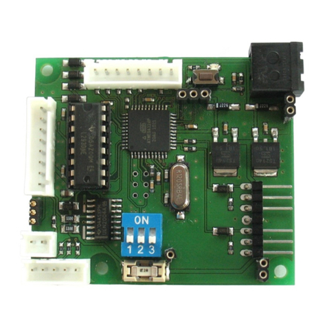
Other ElMod Control Unit manuals

ElMod ThinkTank Tank Module PRO II Flex Assembly instructions

ElMod

ElMod ThinkTank Tank Module PRO II Flex Assembly instructions

ElMod ThinkTank Tank Module PRO II Assembly instructions

ElMod

ElMod ThinkTank Tank Module PRO II Assembly instructions

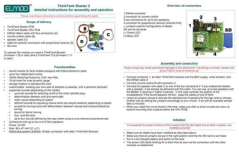
ElMod ThinkTank Blaster 2 Installation instructions

ElMod

ElMod ThinkTank Blaster 2 Installation instructions

ElMod Famo Assembly instructions

ElMod

ElMod Famo Assembly instructions

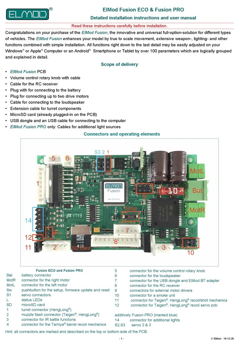
ElMod Fusion ECO Operating and maintenance manual

ElMod

ElMod Fusion ECO Operating and maintenance manual

ElMod ThinkTank Tank Module ECO Flex Assembly instructions

ElMod

ElMod ThinkTank Tank Module ECO Flex Assembly instructions

ElMod M16 v.2.0 Assembly instructions

ElMod

ElMod M16 v.2.0 Assembly instructions

ElMod Fusion ECO Operating and maintenance manual

ElMod

ElMod Fusion ECO Operating and maintenance manual

ElMod ThinkTank Tank Module Assembly instructions

ElMod

ElMod ThinkTank Tank Module Assembly instructions

ElMod ThinkTank Tank Module ECO Assembly instructions

ElMod

ElMod ThinkTank Tank Module ECO Assembly instructions

Popular Control Unit manuals by other brands

Nibe SMS 40 Installer manual

Nibe

Nibe SMS 40 Installer manual

FAAC DAAB EP105 instruction manual

FAAC

FAAC DAAB EP105 instruction manual

SynthCube Fuzz Bucket manual

SynthCube

SynthCube Fuzz Bucket manual

Victaulic 751 FireLock Series Installation, Maintenance, & Testing Manual

Victaulic

Victaulic 751 FireLock Series Installation, Maintenance, & Testing Manual

Sloan G2 Optima Plus Maintenance Guide

Sloan

Sloan G2 Optima Plus Maintenance Guide

Honeywell RV181 installation instructions

Honeywell

Honeywell RV181 installation instructions

encompass AccuMax Quantum Usage instructions

encompass

encompass AccuMax Quantum Usage instructions

Watts LFM110-14 Installation, operation and maintenance instructions

Watts

Watts LFM110-14 Installation, operation and maintenance instructions

PICOLAS LDP-V 03-100 V4.0 user manual

PICOLAS

PICOLAS LDP-V 03-100 V4.0 user manual

RF-Star SimpleLink RF-TI1352B1 CC1352R manual

RF-Star

RF-Star SimpleLink RF-TI1352B1 CC1352R manual

Samson 2422 series Mounting and operating instructions

Samson

Samson 2422 series Mounting and operating instructions

Pfeiffer Vacuum DCU 002 operating instructions

Pfeiffer Vacuum

Pfeiffer Vacuum DCU 002 operating instructions

Honeywell VS8421 installation instructions

Honeywell

Honeywell VS8421 installation instructions

Azbil ACTIVAL FVY5130J Specifications & instructions

Azbil

Azbil ACTIVAL FVY5130J Specifications & instructions

Danfoss PVG 16 PVH/Covers installation guide

Danfoss

Danfoss PVG 16 PVH/Covers installation guide

TECOMAT FOXTROT CP-1003 Basic documentation

TECOMAT FOXTROT

TECOMAT FOXTROT CP-1003 Basic documentation

Siemens SIWAREX JB instruction manual

Siemens

Siemens SIWAREX JB instruction manual

Joy-it Bread Power quick guide

Joy-it

Joy-it Bread Power quick guide

manuals.online logo
manuals.online logoBrands
  • About & Mission
  • Contact us
  • Privacy Policy
  • Terms and Conditions

Copyright 2025 Manuals.Online. All Rights Reserved.