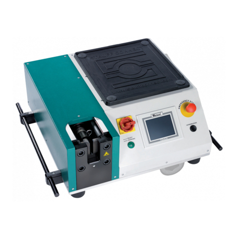
Gates MK2000 User manual

MK2000
User Guide

What’s in this guide……
1. INTRODUCTION…………………………………………………… 3
1.1. GENERAL INFORMATION …………………………. 3
1.2. WORKING PRINCIPLE ………………………………. 3
1.3. CUTTING SECTION ………………………………….. 4
1.4. SPECIFICATIONS …………………………………….. 5
2. INSTRUCTIONS FOR USE ………………………………………… 5
2.1. UNPACKING – INSTALLATION …………………….. 5
2.2. STARTING - USE – CUTTING …………………………. 5
2.3. SAFETY ………………………………………………… 6
3. MAINTENANCE ……………………………………………………. 6
3.1. MAINTENANCE ……………………………………….. 6
3.2. PRECAUTIONS DURING USE …………………………. 7
3.3. WARRANTY ……………………………………………. 7
3.4. SPARE PARTS ………………………………………….. 8
CERTIFICATE OF CONFORMITY 10
2

1 INTRODUCTION
1.1. GENERAL INFORMATION
You have just acquired a GATES MK2000 bench model hose cutting machine
and we congratulate you on your choice.
This sturdy machine will give you long and satisfactory service. To this effect, it
is important to adhere to the enclosed instructions.
The MK2000 is designed to cut all types of hoses from one-wire ¼” to 1” 4-spiral
wire.
All the information concerning the operation, use and maintenance of the
MK2000 can be found in this booklet.
1.2. WORKING PRINCIPLE
CUTTING
This cutter is designed to achieve a clean cut at right angles to the hose if
spreading pins are correctly set. The method employed consists of bending the
hose as it comes into contact with the circular blade, thus reducing friction and
ensuring a clean cut.
ELECTRICAL SYSTEM
The electrical system is comprised of an electric motor and its controls.
A “run-stop” switch supplies power to the motor which is 220/380 V – 3 phase.
3

1.3. CUTTING SECTION
This section is comprised of (figure 1):
- A blade (1) Ø 300mm in hardened steel, directly driven by an electric motor.
- A cutting guide (2) made of 2 bent rods, linked by a lever which moves the
hose through an arc onto the blade.
- The handle (3) provides the leverage required to press the hose onto the blade
to cut.
- A set stop rod (4) for adjustment of guide.
- A return spring (5) for retraction of the cutting guide.
- Two pins (6) fixed to the base.
Figure 1 : Working principle
4

1.4. SPECIFICATIONS
Motor: 220/380 V – 50 Hz – 2,2 kW
Speed: 3000 RPM
Blade diameter: 300mm x 25,4mm x 3mm
Dimensions: H 370 x L 670 x W 490
Weight: 55 Kg
Capacity: 3/16” (option) to 1” 4 spiral wire hose
2. INSTRUCTIONS FOR USE
2.1. UNPACKING – INSTALLATION
ATTENTION!! Lift machine by placing webbings underneath frame ONLY,
NEVER around the motor or cutting head!!
For ease of transport, the machine is delivered with handles removed. Ideally,
the machine should be fixed on a bench with a recommended height of 900mm.
Work area should be clear to allow hose to be easily unwound.
Electrical connection must be carried out by a competent electrician.
Check that the blade rotates in the direction indicated by the arrow on the casing.
If not, reverse two phases.
The machine is now ready to operate.
2.2. STARTING - USE – CUTTING SECTION
Pass the hose through the cutting guide (2).
Hose cutting is achieved by applying a constant gentle pressure to the handle (3).
NOTE!! Extreme force will cause the blade to overheat, thus reducing working
life, and may cause permanent damage to the motor and other moving parts of the
machine.
5

2.3. SAFETY
- Do not put your hand near the rotating blade.
- Before starting, check the electrical connection.
- Always ensure correct direction of rotation, as contra rotation may loosen the
blade.
- The hose must be set in the guide and be supported by the 2 pins (6).
- Never cut at an angle; if the blade deviates from its axis or vibrates, stop
cutting immediately, disconnect from power supply and check condition of
blade.
- Switch off the machine after use. The blade will not stop immediately and
may run silently for some time.
- The machine and blade are designed to cut hoses only. Gates cannot be held
responsible for any other products used.
3. MAINTENANCE
3.1. MAINTENANCE
Before any maintenance or removal of guards, switch off machine and disconnect
from power supply.
This sturdy-built machine requires little maintenance if used as described in this
document.
Only re-sharpening of the blade and renewal of the brush should be necessary in
the years to come.
The slightest crack in the blade indicates that the machine has been used in
abnormal conditions (cutting of different materials or blade overheating for
example) and that the blade requires immediate replacement.
To renew worn parts (blade), remove the casing to gain access.
6

3.2. PRECAUTIONS DURING USE
- A hose requires to be curved as much as possible to avoid causing excess
friction and stalling the motor.
- It is necessary to exert pressure perpendicular to the blade. If not, the blade
could be distorted. An angled cut is also extremely dangerous.
- It is recommended to relieve pressure on the handle if the motor slows down
during the cutting operation.
- The hose must be cropped perfectly perpendicular.
- An angled cut should be systematically rejected as the fitting cannot be
correctly mounted.
3.3. WARRANTY
GATES machines are guaranteed against defects and faulty workmanship for a
period of one year from date of purchase.
During the period of warranty, GATES will repair (or replace as necessary) free
of charge all faulty parts, provided the machine is returned to the works.
This warranty will not apply in the case of accidental damage, misuse or if the
machine has been subjected to repairs or modifications by persons other than
GATES.
GATES cannot be held responsible for any damage or injury direct, indirect or
consequential to the use of its machines, nor after express or implicit termination
of warranty.
This warranty replaces all other warranties including implicit warranties.
7

3.4. SPARE PARTS
The user may carry out repairs himself (after expiry of the warranty period) and,
to this end, the following table and diagram (Figure 2) will help to locate and
order the required spare part.
All orders must state reference, description and quantity required.
Example:
Reference: MK2000-561
Description: Blade
Quantity: 1
Item No. Reference Description Quantity
1 MK2000-1683 Motor 2,2 KW 1
2 MK2000-4332 Motor Sleeve 1
3 MK2000-561 Blade 1
4 MK2000-1675 Blade Guard 1
5 MK2000-1684 Handle Return Spring 2
8

Figure 2: Composition of MK2000
9

CERTIFICATE OF CONFORMITY
Relating to equipment which is subject to automatic certification
The Manufacturer, the undersigned :
Hereby declares that the new equipment described below:
MK2000 – Serial No.
Complies with the regulations regarding health and safety at work, as applicable, and with
the EC European Norm.
Drawn up in on __________________
Signature: __________________
10
Table of contents
Popular Cutter manuals by other brands

Toro
Toro Greensmaster 3150 Series Operator's manual

Phoenix Contact
Phoenix Contact CUTFOX 10 Original operating instructions

Summa
Summa S 75 user manual

Vivid
Vivid Flatbook instruction manual
KRUG+PRIESTER
KRUG+PRIESTER IDEAL 6655 operating instructions
EINHELL
EINHELL TH-MA 1300 Original operating instructions
