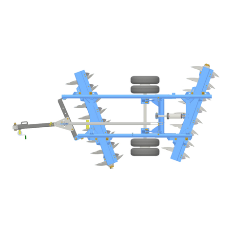
Gates Magnum Coulter Disk User manual

June 2014
Magnum Coulter Disk
124756
Operator’s Manual
®


1 124756 / 6-2014
TABLE OF CONTENTS
FOREWORD . . . . . . . . . . . . . . . . . . . . . . . . . . . . . . . . . . . . . . . . . . . . . . . . . . . . . . . . . . . . . . .3
Preface . . . . . . . . . . . . . . . . . . . . . . . . . . . . . . . . . . . . . . . . . . . . . . . . . . . . . . . . . . . . . . . . .3
Disclaimer . . . . . . . . . . . . . . . . . . . . . . . . . . . . . . . . . . . . . . . . . . . . . . . . . . . . . . . . . . . . . . .3
Contact Information . . . . . . . . . . . . . . . . . . . . . . . . . . . . . . . . . . . . . . . . . . . . . . . . . . . . . . . .3
Owner Registration Information . . . . . . . . . . . . . . . . . . . . . . . . . . . . . . . . . . . . . . . . . . . . . .3
WARRANTY . . . . . . . . . . . . . . . . . . . . . . . . . . . . . . . . . . . . . . . . . . . . . . . . . . . . . . . . . . . . . . . .4
Basic Warranty Repair Period . . . . . . . . . . . . . . . . . . . . . . . . . . . . . . . . . . . . . . . . . . . . . . . .4
Exceptions to this Warranty . . . . . . . . . . . . . . . . . . . . . . . . . . . . . . . . . . . . . . . . . . . . . . . . .4
GENERAL INFORMATION . . . . . . . . . . . . . . . . . . . . . . . . . . . . . . . . . . . . . . . . . . . . . . . . . . . .5
Gates Coulter Disk Features . . . . . . . . . . . . . . . . . . . . . . . . . . . . . . . . . . . . . . . . . . . . . . . . .5
SAFETY . . . . . . . . . . . . . . . . . . . . . . . . . . . . . . . . . . . . . . . . . . . . . . . . . . . . . . . . . . . . . . . . . . .7
Safety Information . . . . . . . . . . . . . . . . . . . . . . . . . . . . . . . . . . . . . . . . . . . . . . . . . . . . . . . . .7
General Safety Practices . . . . . . . . . . . . . . . . . . . . . . . . . . . . . . . . . . . . . . . . . . . . . . . . . . .7
Safety During Transportation . . . . . . . . . . . . . . . . . . . . . . . . . . . . . . . . . . . . . . . . . . . . . . . .7
Safety During Servicing . . . . . . . . . . . . . . . . . . . . . . . . . . . . . . . . . . . . . . . . . . . . . . . . . . . .8
Safety Decals . . . . . . . . . . . . . . . . . . . . . . . . . . . . . . . . . . . . . . . . . . . . . . . . . . . . . . . . . . . .8
Safety Decal Location . . . . . . . . . . . . . . . . . . . . . . . . . . . . . . . . . . . . . . . . . . . . . . . . . . . . .11
Safety Light Operation . . . . . . . . . . . . . . . . . . . . . . . . . . . . . . . . . . . . . . . . . . . . . . . . . . . .14
OPERATION & MAINTENANCE . . . . . . . . . . . . . . . . . . . . . . . . . . . . . . . . . . . . . . . . . . . . . . .15
Tractor Connection . . . . . . . . . . . . . . . . . . . . . . . . . . . . . . . . . . . . . . . . . . . . . . . . . . . . . . .15
Transport to Field Position . . . . . . . . . . . . . . . . . . . . . . . . . . . . . . . . . . . . . . . . . . . . . . . . .18
Start-Up And Hydraulic Operation . . . . . . . . . . . . . . . . . . . . . . . . . . . . . . . . . . . . . . . . . . .19
Maintenance . . . . . . . . . . . . . . . . . . . . . . . . . . . . . . . . . . . . . . . . . . . . . . . . . . . . . . . . . . . .21
Field Operation . . . . . . . . . . . . . . . . . . . . . . . . . . . . . . . . . . . . . . . . . . . . . . . . . . . . . . . . . .25
Side to Side Levelling . . . . . . . . . . . . . . . . . . . . . . . . . . . . . . . . . . . . . . . . . . . . . . . . . . . . .26
Front to Back Levelling . . . . . . . . . . . . . . . . . . . . . . . . . . . . . . . . . . . . . . . . . . . . . . . . . . . .27
Coulter Gang Angle Adjustments . . . . . . . . . . . . . . . . . . . . . . . . . . . . . . . . . . . . . . . . . . . .27
Working Depth Adjustment . . . . . . . . . . . . . . . . . . . . . . . . . . . . . . . . . . . . . . . . . . . . . . . . .28
Optional Harrow and Rolling Basket Adjustment . . . . . . . . . . . . . . . . . . . . . . . . . . . . . . . .29
Transporting from the Field . . . . . . . . . . . . . . . . . . . . . . . . . . . . . . . . . . . . . . . . . . . . . . . . .30
Storage . . . . . . . . . . . . . . . . . . . . . . . . . . . . . . . . . . . . . . . . . . . . . . . . . . . . . . . . . . . . . . . .32
SPECIFICATIONS . . . . . . . . . . . . . . . . . . . . . . . . . . . . . . . . . . . . . . . . . . . . . . . . . . . . . . . . . .33
Coulter Disk Specifications . . . . . . . . . . . . . . . . . . . . . . . . . . . . . . . . . . . . . . . . . . . . . . . . .33
Coulter Disk Dimensions . . . . . . . . . . . . . . . . . . . . . . . . . . . . . . . . . . . . . . . . . . . . . . . . . . .33
TROUBLESHOOTING . . . . . . . . . . . . . . . . . . . . . . . . . . . . . . . . . . . . . . . . . . . . . . . . . . . . . . .34
Troubleshooting Chart . . . . . . . . . . . . . . . . . . . . . . . . . . . . . . . . . . . . . . . . . . . . . . . . . . . . .34
PROPER BOLT USE . . . . . . . . . . . . . . . . . . . . . . . . . . . . . . . . . . . . . . . . . . . . . . . . . . . . . . . .35


3 124756 / 6-2014
FOREWORD
Preface
This Operator and Parts Manual contains information pertaining to the operation, maintenance and adjustments of your
Gates Manufacturing product. To obtain the maximum service, read the manual provided thoroughly. Your Gates
Manufacturing product is designed to give you years of satisfaction. Taking the time to protect it against rust, wear and by
replacing worn parts will add longer life and trade-in value to your product.
Disclaimer
Gates Manufacturing, Inc.’s policy is to improve and develop our products on a continuing basis. We reserve the right to
make changes or add improvements at anytime without incurring any obligation to make such changes on machines
previously sold.
Gates Manufacturing, Inc. recommends that operators READ and UNDERSTAND the Operator’s Manual before using the
machine and should review the machine’s Operator’s Manual annually.
Contact Information
Gates Manufacturing, Inc.
8710 33rd Ave. NW
Lansford, ND 58750
Phone: 701.784.5434
Fax: 701.784.5444
E-mail: [email protected]
www.gatesmfg.net
Owner Registration Information
Bring this information when ordering parts.
Name________________________________________
Address______________________________________
City__________________________________________
State/Prov.____________________________________
Mail Code_____________________________________
Size_________________________________________
Serial Number_________________________________
Date Purchased________________________________
Dealer________________________________________

124756 / 6-2014 4
WARRANTY
Gates Manufacturing, Inc. warrants its new, unused agricultural equipment, to be free of defects in material and
workmanship, when properly assembled, at time of delivery to the first retail purchaser.
Basic Warranty Repair Period
Gates will repair or replace, at its option, without charge for parts any Gates Manufactured part that is found to be
defective for a period of two years. Return of the defective part will be the responsibility of the customer to the dealer
or Gates Manufacturing. It is the dealer’s responsibility to hold the part for inspection by Gates Manufacturing.
Replacement parts are warranted for a period of one year from date of purchase, providing the bill of sale accompanies
warranty claim.
Labor is covered during the first year of warranty only, and at a reasonable rate to be determined by Gates
Manufacturing, Inc. Labor during the second year is not covered.
Exceptions to this Warranty
In no event shall the owner be entitled to recover for incidental, special or consequential damages such as, but not
limited to; loss of profit or revenue, inconvenience of cost of rental of replacement equipment.
Hydraulic hose will be one warranty only.
Blades and springs will be one year warranty only prorated by wear subject to Gates Manufacturing appraisal.
Tires and cylinders will be the manufacturers responsibility.
The buyer of a Serial Numbered Gates product must be reported to Gates Manufacturing, Inc. by the dealer to initiate
warranty.
Use of Gates Manufacturing products for rental units will be warranted for a one year period only.
Mileage and travel time.
Hydraulic Oil.
Repair, maintenance, and service items not related to defects.
• Loss or damage during shipment.
• Failure resulting from lack of or improper maintenance.
• Damage caused by operator abuse, negligence or improper operation.
• Damage due to accidents.
Gates® Manufacturing, Inc.
Lansford, ND 58750

5 124756 / 6-2014
GENERAL INFORMATION
Gates Coulter Disk Features
The Gates Coulter Disk is a primary tillage tool designed to cut and chop heavy residue at higher rates of speed. It
accomplishes this task by using two full ranks of coulter blades set at offset angles adjusted by the operator, which allow
for varying field conditions.
The coulter gangs of the Gates Coulter Disk are adjustable to handle varying field conditions and farming practices. Gangs
are easily adjustable from 0 to 15 degrees to allow for minimal soil disturbance or aggressive soil and residue mixing. This
feature accommodates no till operation to conventional till, and any degree in between. When optional Gates Mounted
Harrows and Rolling Baskets are added to the machine, it becomes an excellent, high speed seedbed preparation tool.
Other features were designed into the Gates Coulter Disk to enhance its performance. Highway service tires are used on
bogie wheel arrangements for maximum flotation in wet conditions. Master-slave hydraulics with rephasing cylinders are
used for single point depth control.
The Gates Coulter Disk is available in varying widths of 24’, 32’, 36’, 40’, 48’, 52’ and 56’ with over-center folding wings
for safe transport.

124756 / 6-2014 6

7 124756 / 6-2014
SAFETY
Safety Information
General Safety Practices
1. READ and UNDERSTAND the Operator’s Manual
before using any equipment. Review at least annually
thereafter.
2. VERIFY all safety devices and shields are in place
before using any equipment.
3. KEEP hands, feet, hair and clothing away from
moving parts.
4. STOP engine, place all controls in neutral, set parking
brake, remove ignition key and wait for all moving
parts to stop before servicing, adjusting or
maintaining.
5. BE CAREFUL when working around high pressure
hydraulic system.
6. DO NOT ALLOW RIDERS.
7. NEVER allow anyone unfamiliar, untrained or
complacent operate the implement.
8. ESCAPING FLUID HAZARD: Escaping hydraulic
fluid under pressure can penetrate the skin causing
serious injury. Relieve pressure before disconnecting
the hydraulic lines.
• Check/tighten all connections BEFORE applying
pressure
• Use a piece of cardboard or paper to search for
leaks.
• NEVER use your hand.
• IF ANY fluid is injected into the skin, seek
immediate attention.
Safety During Transportation
1. ONLY TOW at a safe speed do not exceed speeds
higher than 25 mph (40 km/h). Use caution when
making corners and meeting traffic.
2. ALWAYS use a safety chain between tractor drawbar
and implement hitch when transporting on public
roads.
3. ALWAYS use transport locks when transporting on
public roads.
4. BE SURE implement hitch is securely fastened to
hitch equipped with hammer strap on large tractor
before operating hydraulics.
5. COMPLY with local lighting, marking and oversize
regulations when transporting on highways.
6. FREQUENTLY check for traffic from rear, especially
during turns.
7. BE CERTIAN tractor weight is equal to or greater than
coulter disk weight.
8. ALWAYS be certain that no one is behind or around
implement before moving.
9. BE SURE no upward pressure is exerted on tractor by
coulter disk tongue before disconnecting from tractor.
10. NEVER subject the implement to steep sides / grades
while in transport position.
This safety alert symbol is used to denote possible danger and care should be taken to prevent bodily
injury. When you see this symbol is means: ATTENTION!, BECOME ALERT! and/or YOUR SAFETY IS
INVOLVED!
WARNING: Safe practices must be followed when assembling this equipment. All personnel
involved must:
• Read and understand the instructions and manuals for this machine.
• Be instructed in the safe use of tools and all lifting devices involved in the assembly of this equipment.
• Clear the area of all personnel not involved in the assembly of this machine.

124756 / 6-2014 8
SAFETY
Safety During Servicing
1. SHUT DOWN TRACTOR ENGINE remove key from
tractor ignition and be certain all moving parts have
stopped before servicing harrow drawbar.
2. DO NOT OVERINFLATE tires. NEVER lean over tire
while inflating it.
3. ALWAYS USE proper mounting procedures when
mounting a tire to wheel or rim. A tire not seated
properly may explode when being inflated causing
injury or death.
4. ONLY service coulter disk when in full field position.
Safety Decals
1. Keep safety signs clean and legible at all times.
2. Replace safety signs that are missing or have
become illegible.
3. Replaced parts that displayed a safety sign should
also display the current sign.
4. Safety signs are available from your dealer parts
department or the factory.
How to install safety signs:
1. Be sure that the installation area is clean and dry.
2. Be sure the temperature is above 50°F (10°C).
3. Decide on the exact position before removing the
backing paper.
4. Remove the smallest portion of the split backing
paper.
5. Align the sign over the specified area and carefully
press the small portion with the exposed sticky
backing in place.
6. Slowly peel back the remaining paper and carefully
smooth the remaining portion of the sign in place.
7. Small air pockets can be pierced with a pin and
smoothed out using the piece of sign backing paper.
Indicates an immediate hazardous situation that will result in death or serious injury. The color
associated with Danger is RED.
Indicates a potentially hazardous situation that could result in death or serious injury. The color
associated with Warning is ORANGE.
Indicates a potentially hazardous situation that may result in minor or moderate injury. It may
also be used to alert against unsafe practices. The color associated with Caution is YELLOW.
The Notice decals and statements in this manual are to inform the operator of the correct fluids,
or operational practices for this machine. Failure to follow these notices will result in damage to
the machine. The color associated with Notice is BLUE.

9 124756 / 6-2014
SAFETY
This Page Left Blank Intentionally

124756 / 6-2014 10
SAFETY
Safety Decal Location
GM00073
3
3
4
1
43
2
3
5
5
3
2
3
3
4
1
1
4
3
2
2
4
4
1
4
4
4
4
4
4
4
3
4

11 124756 / 6-2014
SAFETY
Safety Decal Location
The types of safety signs and locations on the equipment are shown in the illustration. Familiarize yourself with the various
safety signs, the type of WARNING and the area or particular function related to that area, that requires your SAFETY
AWARNESS.
IMPORTANT: If Safety Signs have been damaged, removed, become illegible or parts replaced
without safety signs, new signs must be applied. New safety signs are available from
your authorized dealer.
Safety Decals
GM00071
1
GM00036
2
GM00072
34
GM00037
5
Wheel Lift Lock
Wing Lift
Wing Lock
Clearance Decal Red (item 3) and Yellow (item 4)

124756 / 6-2014 12
SAFETY
Safety Decal Location (cont’d)
GM00073
6
6

13 124756 / 6-2014
SAFETY
Safety Decal Location (cont’d)
GM00040
6
SMV (Slow Moving Vehicle) Sign

124756 / 6-2014 14
SAFETY
Safety Light Operation
Figure 1
The Safety Light Kit is equipped with a 7-pin connector.
To protect the 7-pin connector, store in dust cap when not
attached to towing vehicle.
GM00033

15 124756 / 6-2014
OPERATION & MAINTENANCE
Tractor Connection
NOTE: Only tow at safe speed. Use caution when
making corners or meeting traffic.
Turn on flashing warning lights when
traveling on public roads except where such
use is prohibited by law.
To prevent accidental disconnection, use a
safety chain between tractor and implement
when transporting on public roads.
Ensure that a Slow Moving Vehicle (SMV) sign
is at the rear of the implement in clear view of
overtaking traffic.
Figure 2
Lock tractor drawbar in center position, be sure hammer
strap is properly secured on the tractor drawbar.
Using the jack supplied, adjust the height of the
implement tongue to the approximate clevis opening
height of the tractor drawbar.
Figure 3
Back tractor until holes of both hitches align.
Attach implement hitch to tractor hitch with a draw pin
(item 1) locked in place with a hair or D-ring pin (item 2).
GM00030
CAUTION: Use caution when backing
tractor up to implement hitch. Always have
all persons in clear view before proceeding
to back up. Always take tractor out of gear
and set park brake before anyone goes
behind tractor to insert drawbar pin.
CAUTION: Do not lower implement with the
jack in the down position while attached to
the tractor hitch or structural damage will
result.
GM00009
2
1

124756 / 6-2014 16
OPERATION & MAINTENANCE
Tractor Connection (Cont’d)
Figure 4
Install the safety chain on the tractor hitch.
Figure 5
Be sure the safety lock is in the position shown.
Figure 6
Lower the drawbar to release pressure from the jack.
Figure 7
Remove the retainer pin (item 1).
GM00008
GM00007
GM00012
GM00011
1

17 124756 / 6-2014
OPERATION & MAINTENANCE
Tractor Connection (Cont’d)
Figure 8
Rotate the jack to the storage position and install the
retainer pin (item 1).
Figure 9
Turn the crank (item 1) to relieve the pressure on the rear
jack. Remove the retaining pin (item 2).
Figure 10
Move the jack to the storage position and install the
retaining pin (item 1).
Figure 11
Connect the implement hydraulic lines to tractor hydraulic
circuit. The hose ends are color coded according to
function as listed on the chart on the hose storage
bracket.
NOTE: Be sure the hydraulic hose ends on the
implement and female hydraulic couplers
on the tractor are clean before connecting
hydraulics.
GM00010
1
GM00059
12
GM00060
1
GM00035
1
1

124756 / 6-2014 18
OPERATION & MAINTENANCE
Tractor Connection (Cont’d) Transport to Field Position
Figure 12
Figure 13
Remove the retaining pins from the wing locks (item 1)
and lift locks (item 2).
CAUTION: Escaping hydraulic fluid under
pressure can penetrate the skin causing
serious injury. Relieve pressure before
disconnecting the hydraulic lines. Check /
Tighten all connections BEFORE applying
pressure. Use a piece of cardboard or paper
to search for leaks. NEVER use your hand.
IF ANY fluid is injected into the skin seek
immediate medical attention.
GM00019
1
GM00038
2
Table of contents
Popular Farm Equipment manuals by other brands

Smithco
Smithco AER 8 Aerifier Parts & Service operators

Amazone
Amazone EasyCheck Original operating manual

GREAT PLAINS
GREAT PLAINS PL5700 Predelivery Manual
Kongskilde
Kongskilde 800 Series Assembly Instructions & Operating Guide

PRONAR
PRONAR T679/5 Operator's manual

Opico
Opico Air 8 Electronic operating instructions
