TKS 3742 User manual
TKS Operator’s manual
1
Operator’s manual 3742 Potato planter EN, issue 2007-12
Operator’s manual
Mounted 4-row
potato planter
3742 UH124411

TKS Operator’s manual
2

TKS Operator’s manual
3
CE certificate of conformity
We,
TKS Mekaniske
Torlandsvegen 3,
N-4365 Nærbø
Norway
declare under our sole responsibility that the product:
4-row potato planter 3742
has been built in conformity with the Machine Directive 2006/42/EC and meets the
relevant fundamental health and safety requirements.
Kverneland, 13 December 2007
Henning Thunheim
Managing Director
Enter here the serial
number of your machine:
TKS, manufacturers of farm machinery reserve the right to change designs and/or
specifications without notice. This does not include an obligation to make changes to
machines previously supplied.

TKS Operator’s manual
4
Guarantee
TKS products are guaranteed for a period of one year from the date of delivery, against defects in
material and workmanship.
Components not manufactured by TKS, i.e. electrics and hydraulics, PTO shafts and tyres are
guaranteed according to the original manufacturer’s recommendation.
The components listed below have limited guarantee due to their function:
Tyres
Share and share points
Pins
Fuses
Hydraulic seals of motors, valves and cylinders.
Oil filter
Weakening due to wear and tear is considered to be normal for these parts. The product
guarantees for these components are limited to manufacturing defects, breakage, poor
workmanship, transport damage etc on new machines.
Any damage to bearings that are fitted with grease nipples is not covered under the standard
product guarantee, if the damage is shown to be caused by rust or due to the ingress of liquids.
Such damage is caused by insufficient lubrication or the use of low quality lubricants.
Any damage caused by the use of corrosive additives in or nearby the machine is also not
covered.
If a failure is expected to be covered under the guarantee, the owner or its representative should
inform the dealer when parts and/or repair work is required. Any guaranty claim should be applied
for within the period of guarantee.
The dealer should fill in one guarantee claim form for each matter and forward it to the TKS
representative before the 10th of the following month after the claim was raised.
The damaged parts should be marked with the number of the corresponding warranty claim and
should be stored for 6 months by the dealer, available for inspection by the TKS representative if
required.
Due to the operation of the TKS products being out of the manufacturer’s control, the guarantee
covers the product quality only. Performance or any consequential losses are not covered.
The guarantee may be invalid if:
a) spurious spare parts are used or the product is repaired or modified without the TKS
authorisation.
b) operator’s and service instructions given by the manufacturer are not complied with.
c) The machine is used for other purposes than those designed for.
The guarantee does not cover damage caused by normal wear.
Public safety regulations require from the manufacturer of this machine that all safety aspects
regarding the use of the machine is thoroughly evaluated. As a result of these obligations TKS and
its representative are not responsible for the function of components not shown in the spare parts
catalogue covering this product.
TKS reserve the right to change the product with no obligation to previously supplied machines.
NB! It must be possible to identify all enquiries relating to this product’s serial number; see
page 7 Machine identification.

TKS Operator’s manual
5
Content
CE-Certificate of conformity. . . 3
Guarantee. . . . . . . . . . . . . . . . . . . . . . . 4
Introduction . . . . . . . . . . . . . . . . . . . . . 6
Machine identification. . . . . . . . . . 7
Technical specifications. . . . . . . . 8
Dimensions . . . . . . . . . . . . . . . . . . . . . 9
Model descriptions . . . . . . . . . . . . 10
Safety. . . . . . . . . . . . . . . . . . . . . . . . . . . 12
1 Preparing a new machine. . . . . . . 19
1.1 Packing . . . . . . . . . . . . . . . . . . . . . 19
1.2 Row width control . . . . . . . . . . . . . 19
1.3 Assembling the coverers . . . . . . . 20
2 Tractor requirements. . . . . . . . . . . 21
3 Tractor connections. . . . . . . . . . . . 22
3.1 Threepoint linkage . . . . . . . . . . . . 22
3.2 Clamp . . . . . . . . . . . . . . . . . . . . . . 23
3.3 Hydraulic drive . . . . . . . . . . . . . . . 24
4 Mechanical drive. . . . . . . . . . . . . . 28
4.1 Sticker planting spacing 3742. . . . . .
Mechanic models. . . . . . . . . . . . . 30
4.2 Sticker planting spacing . . . . . . . . . .
extra short 3742 . . . . . . . . . . . . . . 31
5 Operating the machine . . . . . . . . . 32
5.1 Seed potato size. . . . . . . . . . . . . . 32
5.2 Altering the row width . . . . . . . . . . 32
5.3 Planting spacing adjustment. . . . . 32
5.4 Depth adjustment . . . . . . . . . . . . . 32
5.5 Covering up. . . . . . . . . . . . . . . . . . 33
5.6 Working speed . . . . . . . . . . . . . . . 33
5.7 Belt agitation. . . . . . . . . . . . . . . . . 34
5.8 Regulation of potato flow . . . . . . . . .
from hopper to planting units . . . . 35
5.9 Emtying the potato hopper. . . . . . 35
5.10 Markers. . . . . . . . . . . . . . . . . . . . 36
6 Electronic control panel . . . . . . . . 38
6.1 The keys of the control panel . . . . 38
6.2 Connecting the tractor . . . . . . . . . . .
power supply. . . . . . . . . . . . . . . . . 38
6.3 Panel display. . . . . . . . . . . . . . . . . 40
7 Maintenance . . . . . . . . . . . . . . . . . 50
7.1 Maintenance of mechanic. . . . . . . . .
components . . . . . . . . . . . . . . . . . 50
7.2 Maintenance hydraulics . . . . . . . . 51
7.3 Maintenance electrics/electronics. . .
equipment. . . . . . . . . . . . . . . . . . . 51
8 Trouble shooting . . . . . . . . . . . . . . 52
Notes. . . . . . . . . . . . . . . . . . . . . . . . . . 53

TKS Operator’s manual
6
Introduction
We congratulate you on the purchase of your new TKS product. You have chosen a product which
will give you satisfaction through a network of efficient dealers where function, finish, after sales
service and spare parts are always at hand.
All TKS products are designed and tested in close co-operation with farmers and contractors to
ensure optimal function and reliability.
Please read this manual before using your new machine.
We wish you all the best with your TKS product.
Yours faithfully
TKS Mekaniske AS
TKS Mekaniske
Torlandsvegen 3,
N-4365 Nærbø
Norway
Phone : + 47 51 43 63 00
Fax : + 47 51 43 48 62
TKS Operator’s manual
7
Machine identification
The machine’s serial number and the manufacturer’s address are found on the number plate of the
machine. See illustration below.
The serial number and year of manufacture for this machine is given below. This number is
important with regard to service and the correct supply of spare parts.
The machine is marked CE. This marking with appurtenant EU statement of agreement means that
the machine complies with substantial health and security demands, and that it is accordance with
the Machine Directive 2006/42/EC
I3742_08

TKS Operator’s manual
8
Technical specifications
Model 3742
Number of rows 4
Connection to tractor Kat. 2 and 3
Row width (intervals of 5 cm) 75 cm - 90cm
Planting intevals (electro-hydraulic model) infinite variable 10 - 80
cms
Planting intevals (mech. model) std. 14-69cm,
extra 10-49 cm
Hopper capacity
potatoes 2000 kg
Minimum filling height, potatoes 118 cm
Wheel dimension 7.50-16 4 PLY lugged
Monitor
Track width 150 - 180 cm
Weight empty machine 1800 kg
Working speed 4-10km/t
Extra equipment
(Wheel dimension)
Marker arms
Floating opening shoe (delivered instead of standard).
Floating opening shoe (delivered as kit)
Electric cup belt agitators
Insert cups - small
Insert cups - medium
Automatic depth control
Adjusting kit from 75-80 til 85-90 cm row width
Adjusting kit from 85-90 til 75-80 cm row width
Hopper sensor
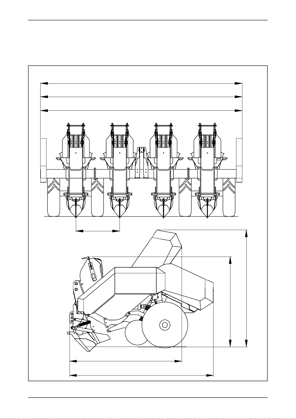
1917
2460
1999
1542
3450 (R = 75 cm)
3600 (R = 80 cm)
3900 (R = 85 - 90 cm)
R
TKS Operator’s manual
9
IK1_05
I3742_09
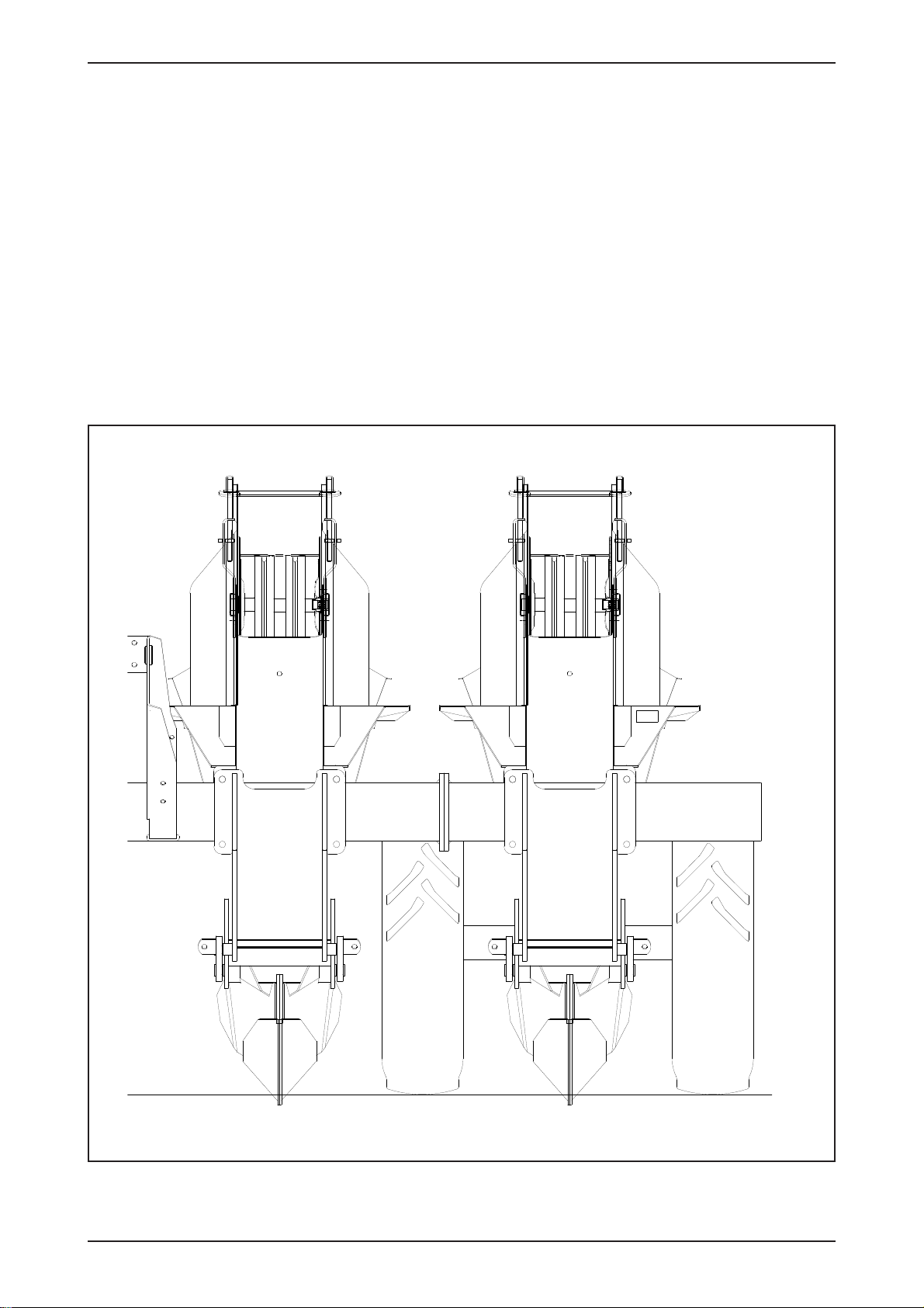
Dimensions
Valid for machine with wheel size 7.50-16 4 PLY lugged left and right.
All dimensions are in mm (1” = 25.4mm)

TKS Operator’s manual
10
Model descriptions
The 3742 automatic potato planter from TKS is a four row mounted machine. The planting units
include double cup belts, adjustable gate between hopper and planting unit, adjustable row width,
choice between mechanicall and electronic/hydraulic drive systems, infinite planting distance
adjustment, rigid furrow openers and manually or automaticcally controlled planting depth.
The machine is available as follows:
• 4-row- basic machine, row width 75cm
• 4-row- basic machine, row width 80cm
• 4-row- basic machine, row width 85cm
• 4-row- basic machine, row width 90cm
The machine is equipped with hydraulic hopper 2000kg
The machine is equipped with double cup belt.
Choose between following cup types:
• Planting cup Ø66mm (steel inserts for reducing to Ø55 available)
• Planting cup Ø74mm (steel inserts for reducing to Ø65 available)
• Planting cup large (white plastic inserts for reduction to medium size available)
(green plastic inserts for reduction to small size available)
The machine is delivered with disc roller 450mm for covering up each row.

TKS Operator’s manual
11

TKS Operator’s manual
12
Safety
Before operating, adjusting or servicing the
machine it is important that the safety instructions
in this manual are carefully read and understood
by those, which are directly concerned. (Fig. 1)
Whilst all care and attention has been taken in the
design and production of this machine, as with
all machinery there remains a certain amount of
risk to personnel whilst the machine is in use. It is
strongly recommended that users and operators
take all possible precautions to ensure both their
own safety and that of the others that may be in
the vicinity.
Read and observe the safety instructions in this
manual.
Safety is your responsibility!
Pay particular attention to this symbol. It
means that there could be a serious hazard. It
emphasises precautions, which have to be
complied with in order to prevent accidents.
This symbol can be found throughout this manual
and on the warning signs of the machine. They
are for your safety and should be observed at all
time.
Be careful when other people or animals are
close by!
Never start the machine when people or animals
are close by tractor or machine. Never stand
between the tractor wheels and machine. (Fig. 2)
Bear in mind regulations regarding the lower age
of operators of this kind of machines.
Use of the machine
The machine should be used only for the purpose
it has been designed for.
Use personal protection devices
Do not wear loose clothing, which might catch in
any of the moving parts. In dusty conditions an
approved mask must be used. (Fig. 3)
Take care of excessive noise level. Some tractor/
implement combinations, depending on
conditions, may cause noise level beyond 85dB
at the operator’s ears, even in a “Q” cab. In these
conditions ear defenders must be worn. Keep cab
windows and doors closed to reduce noise level.
The machine must be connected to a correctly
sized tractor
The weight of the tractor must correspond to the
maximum weight of the machine when operated.
Follow domestic law and regulations. (Fig. 4)
Make sure that the tractor has the correct PTO
gear engaged. A machine designed for an input
speed of 540 rpm. should never be connected to
a tractor with 1000 rpm. output speed engaged.
The normal PTO speed is given on a label close
to the PTO input shaft.
Connecting machine to tractor
must always be carried out as described in this
manual. If connection should be carried out with
drawbar, one of the parts (tractor or machine’s
drawbar) must have a clevis. The drawbar pin
must be secured with a lock pin. (Fig. 5)
Observe national regulations regarding road
transport. Some countries require the use of
safety chain when a trailed machine is towed
along public roads.
Think of safety while operating the machine
Stop the tractor engine and remove the ignition
key prior to carrying out repairs, cleaning,
lubrication or maintaining the machine. (Fig. 6)
Safety guards
Make sure all guards are in good order and fitted
correctly. Do not attempt to start the machine
before ensuring this. (Fig. 7)
Pay particular attention to the plastic guards of
the PTO shaft. If damaged they must be replaced.
The chain locks of the guards must always be
fitted on a suitable place on the tractor and the
machine to prevent the outer plastic guards
turning.
Hydraulics
Be very careful when dealing with hydraulics. Use
eye protection and gloves. Escaping hydraulic oil
under pressure might penetrate into the skin and
cause serious infection. See a doctor if you have
been exposed to injury. (Fig. 8)
Take care that nobody is close to the machine
when the hydraulic functions are being operated.
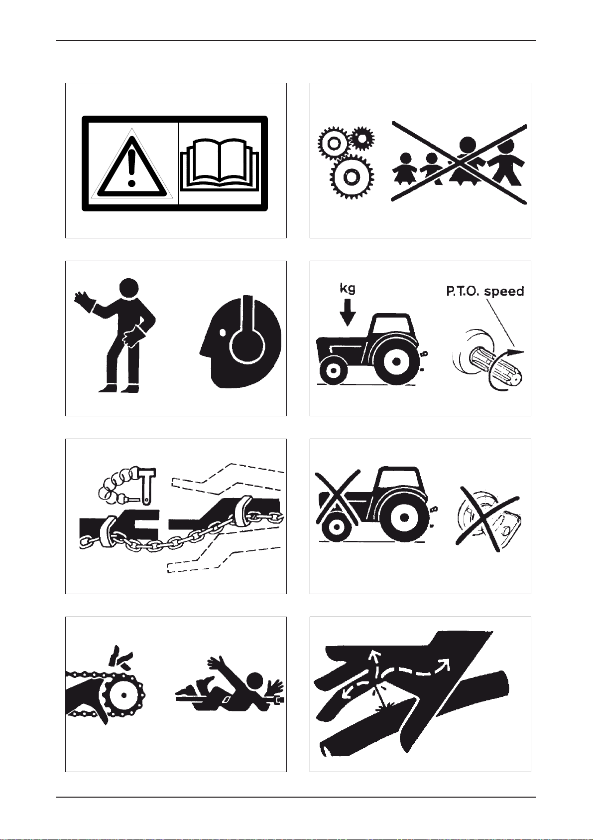
Fig. 2Fig. 1
Fig. 3 Fig. 4
Fig. 6Fig. 5
Fig. 7 Fig. 8
TKS Operator’s manual
13

TKS Operator’s manual
14
When disconnecting machine and when
leaving tractor/machine
When disconnecting, all hydraulic functions must
be in neutral position. The machine must be
lowered to the ground and be safely secured. If
the machine has parking chocks they should be
used at the wheels. Never allow children to play or
stay near agricultural machinery. (Fig. 9)
Drive safely
Beware of your responsibility, - carelessness or
negligence may cause serious injury or even
death. (Fig. 10)
Prior to transporting the machine along public
roads, check wheel bolts and couplings.
Disconnect or lock the hydraulic system.
Drive carefully. Reduce speed when turning and
driving on uneven ground. Take care that trailed
machine does not start swinging or become
unstable.
Please be aware of the danger of overturning
when working on slopes and in soft ground.
Reduce load.
Lights
The owner and operator is responsible of
providing correct lamps and reflectors on the
machine when transported on public roads.
Comply with public regulations. (Fig. 11)
Safety equipment
Always carry first aid equipment on the tractor.
Also observe the regulations concerning fire
extinguisher. When working with burning
materials like hay and straw a fire extinguisher
must be available at all times. (Fig. 12)
Spare parts
For safety reasons use only original spare parts.
The use of spurious spare parts will cause the
product guarantee to be invalid. (Fig. 13)
Maintenance
Take care that the machine is properly maintained
and kept in good safe working condition.
Never change the basic technical construction of
the machine.
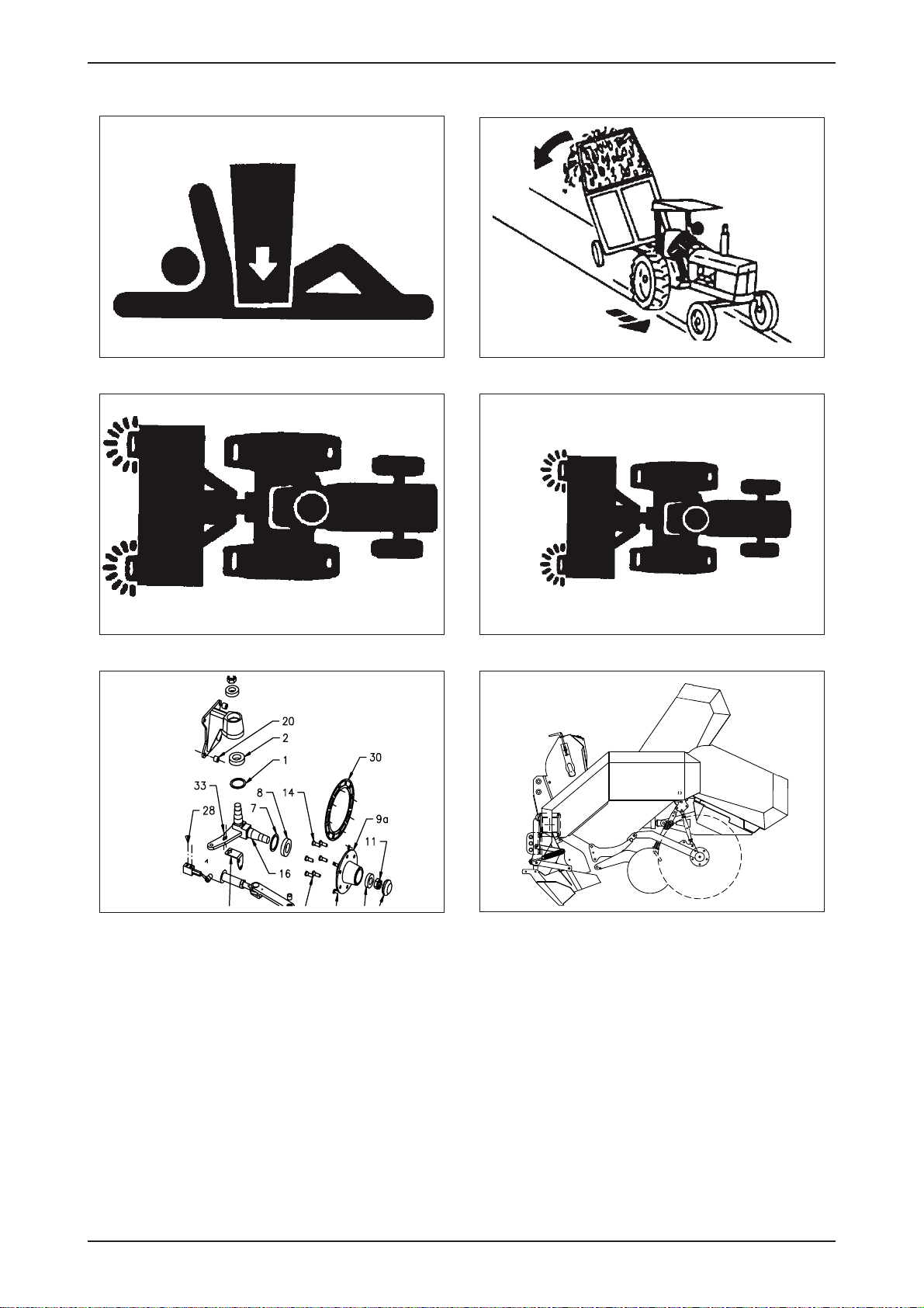
Fig. 10Fig. 9
Fig. 11 Fig. 12
Fig. 13 Fig.14
TKS Operator’s manual
15
TKS Operator’s manual
16
Supplementary safety instructions
for the 3742 potato planter
This machine is designed and built for planting
potatoes or similar root crops.
The machine is equipped with warning
signs.
If any of the decals are damaged, they must be
replaced. Ordering numbers are shown on the
illustrations in this paragraph.
Warning sign UH220532
Be careful! Read and understand the
instructions in the manual before the machine is
put into service and before attempting
adjustment/maintenance.
Warning sign UH220525
Warning sign UH220525. Be careful when
machine is lowered! Keep feet away from
furrow openers, ridgers and wheels. When
operations are to be performed underneath a
raised machine, a support should be placed
under the main frame.
Warning sign 220526
Risk of cutting fingers if catched between roller
chain and sprocket.
Warning sign 220536
Keep distance to the movable hydraulic
operated potato hopper.
Warning sign UH220534
Disconnect all electronics before welding
commences.
Lifting machine with
crane
Only use approved lifting device. The weight of
the machine is given in paragraph “Technical
specifications”.
Be careful! Make sure that nobody stands
under or near the machine when it is being
lifted.
Attach the lifting straps by the “sling here”
signs. Make sure that straps are securely
fastened before lifting.
Use a guide wire to keep machine in position.
Hazard at use of
chemicals
The chemical manufacturer’s
prescriptions regarding handling of pesticides,
insecticides and fertilizer should be noticed.

UH220532 UH220525
UH220526 UH220536
TKS Operator’s manual
17
UH220534

TKS Operator’s manual
18
New machine - be careful
Read the operator’s manual. Great care must
be taken when starting a brand new machine
for the first time. Incorrect assembly, faulty
operations etc. may cause expensive repairs
and loss of profit. The Underhaug product
guarantee does not cover damage occurring
when the instructions given in this book are not
followed.
Pay particular attention to this symbol, - it
emphasises operations where great care must
be taken in order to avoid incorrect assembly,
faulty operations etc.
Carefully do as described below when starting a
new machine.
Check that the machine is mounted correctly
and that it is not damaged. Assure that
electric wirings have length and position that
allow machine to move without causing any
damage to the wirings.
Check the connections between tractor and
machine.
Check that the roller chains are tensionned and
correctly positioned on the sprockets.
Check that the drive rollers on top of both
planting tubes are equally adjusted in order to
assure cup belts run straight.
Lubricate the machine according to lubrication
instructions.
Check wheel bolts torque setting.
Cleaning
General
We recommend the use of pressured air when
cleaning the machine. Thus there is less risk of
damaging the bearings of the machine. If high
pressure water is used, keep clear of bearings
and electric components.
Cylinders
Assure that piston rods are kept free from
aggressive chemicals in order to avoid
corrosion.
TKS Operator’s manual
19
1. Preparing a new machine
1.1 Packing
Remove all kind of packing material. Any equipment stored in the machine should be
removed.
1.2 Row width control
Check that row width is in accordance with customer’s specifications.
The row width could preferential be ordered directly from the factory, since it is quite labour
damanding to change the row width.
4-row basic machine, row width 75cm
4-row basic machine, row width 80cm
4-row basic machine, row width 85cm
4-row basic machine, row width 90cm
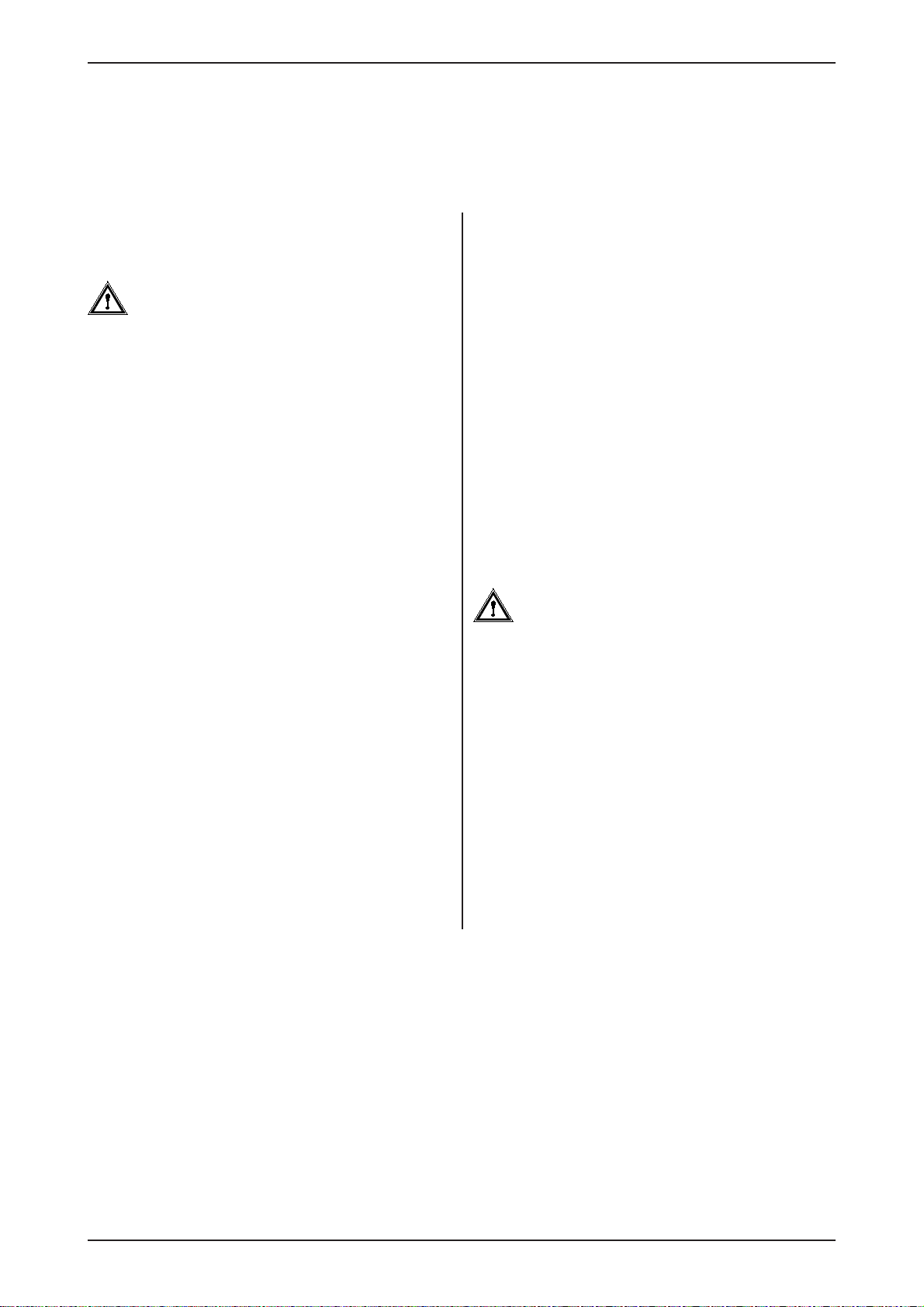
I3742_07
Fig. 20
A
A
B
D
C
TKS Operator’s manual
20
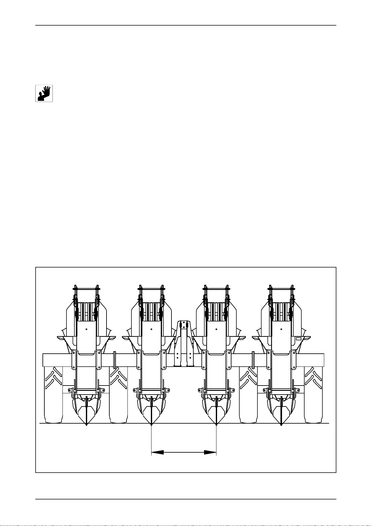
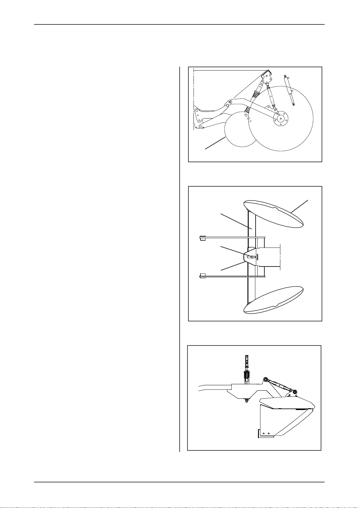
1.3 Assembling the coverers
Disc coverer Ais attatched to the arm B, and
right and left coverer is attatched to the center
of the frame plate C. Adjust the angle of the disc
rollers by moving the fixing point Dfor the disc
arms forward and backward on the frame plate.
Ridging hood (fig. 25):
Is ready for use when factory fitted.
Fig. 23
Fig. 24
Fig. 25
I3742_01
I3742_02
Table of contents
Other TKS Farm Equipment manuals


