Scotts Trinity6000 User manual

Operators Manual
British Built Innovation & Quality
Scotts Precision Manufacturing Ltd
Slate Worx
Station Road Tel: +44 (0) 205 270 28
Eastville Fax: +44 (0) 205 270 89
Boston Email: scottymail@btconnect.com
Lincolnshire. UK Web: http://www.scottsuk.com
PE22 8LT

Machine serial number: T616…
Year of manufacture: 2016
(Please quote these when ordering any spare parts from our parts department)

Table of ontents
Category Page
Foreword
Spare Parts Ordering and Advice 2
General Machine Safety 3
Safety Instructions using a PTO shaft 4
Hydraulics System Safety 5
Warning Symbols and Advice 6
Functions and operations of the Haulm Topper 7
Adjustments to get the best from your Trinity 6000 3
Hitching the machine 8
Transporting the Machine 20
Un-hitching the machine 2
Maintenance 22
Cleaning the Machine 23
Mechanical Drives 25
Lubrication Points 28
Technical Data/ Notes 29
Warranty Terms and Conditions 30

Foreword
Thank you for purchasing this Trinity 6000 3 Bed Haulm Topper, we use only
the finest quality materials and workmanship to give you a machine of the
highest standard of quality and with added innovation to create a machine of
exceptional value.
These operating instructions are designed to give you important information
on the safety aspects of operating the machine, avoiding danger and
maximising productivity, whilst reducing repair costs and downtime.
Following the advice of this manual will increase reliability and service life of
the machine and ensure all users safety.
Please ensure ALL users have access to this manual whenever the machine
is in use, failure to do so could result in personal injury.
Please ensure all users of the machine have read and fully understood these
instructions prior to using the machine and are aware of all the dangers
involved in using this machinery.
Safety
Any persons working on or with the machine must be reliable, competent
and above the statutory age limit. Only authorised personnel can work on or
with this machine. Any work needed to be carried out on electrical or
mechanical parts must be carried out by qualified personnel and if in
training, under the supervision of suitably trained personnel. Failure to
follow any of these instructions can lead to risk of injury to you and other
people as well as causing damage to the environment or the machine.
All advice in this manual must be observed. Failure to do so can result in all
claims for damages becoming invalid.
The advice we offer in this manual contains basic advice which should be
observed during setting-up, operation and maintenance.
Please note Scotts Potato Machinery accepts no liability on the following: -
• Any damage to agricultural produce or other items which occurs as a
result of operating and adjustment errors or other incorrect usage
• Damage caused as a result of operations not complying with the
designated use of the machine.
• Damage caused by the use of parts, accessories or ancillary equipment
not supplied and/or not approved by Scotts Potato Machinery
• Conversion of or modifications to the machine not carried out or
authorised by Scotts Potato Machinery
Page 1

Symbols used for the purpose of important advice within this operating
manual.
Text marked with this symbol refers to the possibility of
accidents or injury hazards.
This symbol indicates necessary functions or actions that
must be carried out.
Spare Parts Ordering and Advice
Manufacturer’s address:
Scotts Potato Machinery
Slate Worx
Station Road
Eastville
Boston
Lincolnshire
PE22 8LT
United Kingdom
Tel: +44 (0) 205 270 28
Fax: +44 (0) 205 270 89
Email: [email protected]
Web address: http://www.scottsuk.com
When ordering spare parts for the machine please quote Machine type i.e.
Trinity 6000 Haulm Topper and Machine Serial No. (This can be found on an
identification plate attached to the end of the beam).
Please do not remove, change or render illegible for legal
reasons the machine identification plate.

Page 2
General machine Safety and accident prevention
All aspects of safety advice, whether through this manual or by national
accident prevention regulations must be observed: -
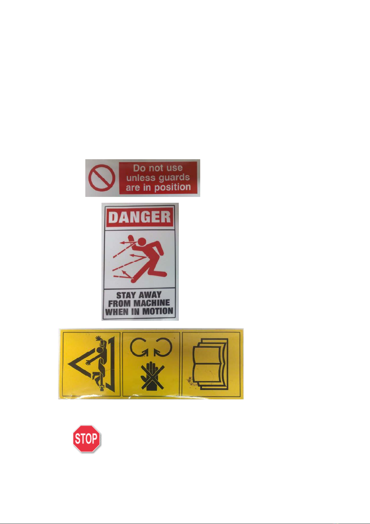
• Warning signs and other notices on the machine are there to provide
you with visible important information for safe operation of the
machine and to reduce the risk of personal injury.
• Before attempting to start work, please familiarise yourself with all
equipment and controls and the functions they perform.
• Please ensure any users wear close-fitting clothing. Avoid using loose
fitting clothing.
• Keep the machine clean at all times to see visible signs of wear.
• Check around the machine before starting it up, to ensure there are no
obstacles in the way (including people) and ensure you have adequate
all round visibility.
• Only start the machine up if all protective guards are fitted correctly
and in their protective positions.
• Dangerous parts are located behind the protective covers/ guards.
These do not necessarily come to a standstill when the drive is
switched OFF. Therefore, keep well clear until such parts have come to
a complete standstill.
• Only carry out maintenance, repair and cleaning work underneath the
machine when connected to tractor with handbrake engaged, engine
switched off and with suitable axle stands supporting the machine.
• NEVER allow persons to stand on the machine whilst working.
• The designs and functions of intake and discharge mechanisms i.e.
rotating shafts, conveyors etc. means they cannot be fully protected.
Therefore always keep a safe distance from such moving parts when
the machine is in operation. This advice also applies to any ancillary
equipment.
• Only carry out maintenance, repair and cleaning work on the machine
when the drive is switched OFF and the engine is stationary. Remove
the ignition key from the towing vehicle.
• NEVER stand in the area of discharge.
• NEVER allow persons to ride on the machine whilst moving.
• Switch OFF the engine and remove the ignition key before leaving the
towing vehicle.
• The designs and functions of intake and discharge mechanisms i.e.
webs’, sifting units, etc. means they cannot be fully protected.
Therefore always keep a safe distance from such moving parts when
the machine is in operation. This advice also applies to any ancillary
equipment.
• NEVER allow persons to stand between the towing vehicle and the
machine unless the machine is secured against rolling away by the
means of parking lock and/or wheel chocks.

Page 3
• Secure all moving parts against movement during transportation, using
the safety devices provided.
• Remember when hitching/unhitching to/from the towing vehicle to
avoid the risk of injury.
• Hitch up the machine in accordance with the instructions and only to
the specified devices.
Safety instructions using a power take-off (PTO) shaft
• Only use the universal drive shafts specified by the manufacturer!
• The universal drive shaft housing, PTO shaft guard and guard cones
must be fitted at all times and in good condition.
• Please ensure that operating instructions for the universal drive shaft
are observed and fully complied with by all operators.
• Only attach and remove the universal drive shaft when the PTO shaft is
disengaged, the engine switched OFF and the ignition key removed.
• Always make sure that the universal drive shaft is fitted correctly and
is secure.
• Attach the chain at all times to prevent the guard from turning!
• Before engaging the PTO shaft, make sure that no persons are within
the danger area of the machine.
• Before engaging the PTO shaft, ensure that the selected speed and
direction of rotation of the towing vehicle’s PTO shaft agree with the
permissible speed and direction of rotation of the machine.
Only carry out work on the machine when the engine is
switched OFF, the ignition key removed and the machine
secured against rolling away.
Adjust universal drive shaft to suit towing vehicle when
first attaching to or changing the towing vehicle.
An operating manual is supplied with every universal drive
shaft. Exact instructions on how to adapt the length of the
shaft can be found here.

Page 4
ydraulics System Safety
. The hydraulics system is under high pressure!
2. Inspect the hydraulic lines at regular intervals and replace where
necessary. Check for signs of damage and/or ageing. Hoses and hose
couplings will undergo a natural ageing process, even if looked after
and stored correctly. Their storage time and service life is therefore
limited. When checking for ageing, always take the danger potential
into consideration.
3. Replacement lines must comply with the machine manufacturer’s
requirements.
4. Hydraulic fluids escaping under high pressure can penetrate the skin
and cause serious injuries. If such injuries occur, medical attention
must be sought immediately to prevent risk of infection.
5. Before working on the hydraulics system, the machine must be
lowered, the hydraulic system de-pressured and the engine switched
OFF.
Exercise extreme caution when connecting hydraulic
lines.
Take extreme care when working on a hot hydraulic
system. Risk of serious burns.
Route the hydraulic supply lines so that they cannot
become pinched or ruptured.
Use only hydraulic fluid specified by the
manufacturer on the towing vehicle.
Page 5

Warning Symbols and Advice
The warning symbols are to indicate dangerous areas of the machine and
specific operations for safety and trouble-free operation.
Please follow all warning symbols and information stickers at all times!
Always ensure warning symbols and information stickers are kept clean and
in legible condition. Any stickers that are not legible must be replaced
immediately and attached in their designated positions on the machine.
Do not remove or render illegible any warning
stickers. Replace any immediately if this
happens.
Page 6
All gu
ards must be
securely closed when
machine is running.
Keep well clear of
the machine
when working to
avoid flying
objects/ debris.
Ensure PTO
guard tubes/
cones are present
and are not
damaged.

Functions and operations of the aulm Topper
Exercise extreme caution when performing any
adjustments to the machine.
The Trinity 6000 Haulm Topper is designed to chop haulm and remove it
from the top of the ridge prior to lifting the crop. To reduce the need for an
expensive and generally high maintenance cross conveyor, shear plates have
been utilized to give a similar effect of a straw chopper. This in turn finely
chops the haulm to the point where the following potato harvester can sieve
the debris without the use of haulm rollers.
The working width is increased to 6 metres to allow flailing of the adjacent
beds and thus avoid trampling of the haulm by tractor wheels.
The smaller diameter rotor tube and increased flail length variation improves
the toppers suction and drastically improves the spreading of the haulm.
This offers an improved opportunity of a cleaner stem/ target area for
spraying. The flails are located in pairs via a single quick release pin to
rapidly decrease replacement time.
onnecting the Topper to the tractor
Front Unit:
The single Topper unit is to be mounted on the front 3 point linkage. There
is a range of different mounting positions on the headstock to suit various
different towing vehicles. Use the mounting slots which suit your tractor
most appropriately. The single unit uses a Cat. 2 linkage.
Page 7

Rear Unit:
The rear unit is hitched up to the towing tractor with the 3 point linkage on
the back of the tractor. There are 2 positions for the top link- use the one
most suitable for your tractor. The rear topper unit uses a Cat. 3 linkage.
Page 8
Depth wheels
The depth wheels have been designed to
adjust the cutting height of the flails. To
adjust the height, firstly slacken off the
clamp bolt on the outer part of the leg
and then release the elasticated hook
from the handle. Adjust to desired height
with the handle, then replace the hook
and tighten the clamp bolt.
Depth wheels can also
be
adjusted to suit any row
widths by simply
slackening off the 4 x
M 2 bolts and sliding to
the desired position.
Clamp bolt
Elasticated
hook
Adjuster
handle

Shear plates and flails
The shear plate and flails are designed and configured to chop the haulm into
small pieces. This is only possible if both the shear plates and the flails are
in good condition (i.e. not worn out) and they are adjusted correctly. If
different length flails are fitted to achieve a different row width configuration,
the corresponding shear plates must be changed as well.
Row widths
This Topper has the ability to be configured to top a range of different row
widths. Row width settings are as follows: 34”-36”, 30”-32” and full width
beds. For ease and increased speed when changing flails, 2 flails are held in
place with x M20 x 80mm bolt.
Page 9
PTO Shafts
The topper units are driven via a
PTO shaft into a gearbox and then
through a secondary PTO shaft to
the pulley. Ensure all PTO shafts
are lubricated according to the
instruction sheet supplied with
new PTO’s. It is imperative that
both PTO’s have their correct
guard cones and covers on at all
times and that they are in good
condition.

Page 10
Front gearbox
The front gearbox is able to run
in either direction (clockwise or
anti-clockwise) to suit the output
shaft direction fro
m the tractor.
In order to achieve a different
direction, the gearbox simply
needs turning over.
Bearing housing
The secondary PTO shaft is
attached to a short shaft which
runs through a bearing housing.
There are 3 sealed bearings in
the housing and also an extra
seal at each end to ensure that
no dust/ foreign bodies can
damage the bearings. Due to
this housing using sealed
bearings, there is no need to
grease them.
If the long PTO shafts on the rear units are removed for any reason,
they must be timed when they are replaced. This means that the yokes
must be in line:
Each rear unit has a
n overrun clutch which enables the rotor to slow
down at an appropriate/ correct speed once the PTO is disengaged.

Rotor Drives
The rotor is driven by a series of 4 ‘V’ belts. The drive and driven pulleys are
attached to the drive shaft/ rotor using heavy duty taper lock bushes. Below
are the combinations of drive and driven pulleys needed to achieve the
correct rotor speed (i.e. between 50rpm and 300rpm) relating to the
tractor PTO output speed:
• 540 RPM- 90mm Diameter Driven Pulley, 400mm Diameter Drive
Pulley, 4 x SPB 2040 Belts
• 750 RPM- 90mm Diameter Driven Pulley, 3 5mm Diameter Drive
Pulley, 4 x SPB 905 Belts
• 1000 RPM- 90mm Diameter Driven Pulley, 240mm Diameter Drive
Pulley, 4 x SPB 850 Belts
Page 11
Overrun clutch
On the secondary PTO shaft there is
a directional overrun clutch. The
overrun clutch enables the rotor to
slow down at the correct speed
after the PTO has been disengaged.
Adjuster
bolt
Taper
lock bush
Driven
Pulley
Drive
Pulley
V belts
(x4)
Taper
lock bush

Bed Width Adjustment
The trinity 6000 is designed to cover bed widths from .7m to 2m. to adjust
the bed widths, slacken off the 8 x M20 bolts and slide unit along the arm to
the desired position.
Page 12
Bash Guards
The Topper is fitted with a ‘Bash Guard’
on either side of the unit. The purpose
of the bash guard is to protect the ends
of the rotor, the pulley and the guard
from coming into contact with any solid
objects. The bash guards are hinged to
allow easy access to the pulley guard
etc.
Optional 3 point linkage
extension kit
Certain tractors (most Fendt’s for
example) have very short front lift
arms. This means the topper is too
close to the tractor and therefore
prevents the depth wheels being
fitted to the correct side of the
topper. To remedy this, an extension
kit is available which moves the
headstock out a further 200mm away
from the topper and allows the depth
wheels to be fitted correctly.

Float springs
The 2 rear units are mounted on separate floating parallelogram linkage.
The parallelogram linkages have a spring incorporated into them to allow
each unit to float to follow the contour of the bed. When setting the cutting
height, ensure that the spring is in the middle of its travel.
Optional ross onveyor
The Trinity 6000 Haulm Topper can be fitted with an optional cross conveyor
to discharge cut haulm into the tractor wheelings. The cross conveyor is
hydraulically driven from the tractor spool.
Page 13
Optional Ridge Press rollers
This machine can be fitted with an
optional ‘Ridge Press’ kit. The
Ridge Press kit can be supplied with
either steel diablos or pneumatic
tyres. The function of the Ridge
Press rollers is to seal the ridge
after topping to eliminate tuber
greening due to sunlight
penetration.

Optional Sprayer System
The Trinity 6000 has the facility to add a full width spray system to it. The
kit consists of x 500 litre tank (centrally mounted), 3 x individually
mounted, galvanised spray hoods and 2 spray nozzles per row (for complete
coverage). The spray system is operated from the tractor cab and is ideally
suited for ‘Flail & Spray’ single pass operations.
Page 14
Spray Hoods
Spray Hoods
Spray Tank
Pivoting Mounting
brackets
Hand
washing tank
NOTE: There is an
additional Operators
Manual for the Spray
System.

Adjustments to get the best from your Trinity 6000
Do not attempt to adjust the settings of the machine
until you have read and understood the information
contained in this booklet.
Only carry out work on the machine when the engine
is switched OFF, the ignition key removed and the
machine secured against rolling away.
utting the PTO shaft to the correct length.
If the PTO shaft is too long it might bind when the three point hitch is lifted
up. Damage might be caused to the bearing of the chipper or to the PTO of
the tractor. If the PTO shaft is too long it must be cut. Both PTO halves
must be shortened by equal amounts.
• Mount the topper on the three-point linkage of the tractor.
• Turn off the engine and remove the keys. Lower the topper on a firm
and level surface.
• Lift the three point linkage so that the power intake shaft of the topper
is on the same height as the PTO of the tractor. The PTO and the
power intake should be closest to each other at that position.
• Pull the PTO shaft apart. Connect one half of the shaft to the topper so
that the locking pin is locked in place. Place the other end of the
topper flush with the end of the tractor's PTO. Lay the ends side by
side. Mark on the shield how much must be cut off. The tubes must be
short enough that they cannot reach the bottom when the topper is in
any position.
• Cut the plastic tube.
• Cut a piece from the profile tube, which is the same length as the piece
which you cut off of the shield.
• Shorten the other half of the PTO shaft to the same length.
• File sharp edges off of the profile tubes.
Depth Wheels
The depth wheels must be checked prior to topping and set up correctly.
There are 2 parts to setting the depth wheels-
• Row Widths- measure from the centre of the topper to the centre of
the wheel. This distance must measure half of the bed width: i.e. if
the bed measures 72”, the distance from the centre of the unit to the
centre of the wheel should be 36”. To adjust this distance, slacken off
the 4 x M 2 bolts ( 9mm socket) and move to the correct position.
Page 15

• Height- needs to be set in relation to the height of the rows/ beds in
every field. The topper needs to be set so that the flails are about
50mm from the row top. Failure to set the topper high enough will
result in damage to flails and damaged crop!
Page 16
Shear Plates/ Flails
The flails and shear plates need to be set to the correct row widths. To do this,
firstly measure and mark the centre of the rotor. Now measure half the
distance of the row width either side of this centre line (e.g. 36” rows- mark 8”
either side of the centre line). Ensure that the shear plate arrangement
corresponds to the flail layout. If the flail arrangement is changed, the shear
plates must be changed as well.
NOTE: If shear plates are not set to the contour of the blades, either poor
topping will result or damage to blades will occur.
This illustration shows
the possible row width
configurations and the
flails/ shear plates
needed to achieve each
one.

Float Springs
Once the cutting height has been set with the depth wheels, set the float
springs to the central position. Use the rear lift on the tractor to raise or
lower the units and set the tractor to ‘position control’. Make sure that the
topper is parallel to the ground by adjusting the top link to suit.
Ridge Press rollers (optional)
The pressure of the Ridge Press rollers needs setting prior to commencing
work. To do this, use a 24mm socket the turn the nut on top of the spring
assembly. Increasing the amount of thread protruding from the assembly
increases the pressure, decreasing the length of thread in turn decreases
pressure.
Sprayer Unit (optional)
If the optional spray system is fitted, for a ‘Flail & Spray’ operation, the
cutting height should be set to leave approximately 50mm of stem. The
chemical application rate will be recommended by your Agronomist or
indicated on the chemical bottle
Page 17
Table of contents
Other Scotts Farm Equipment manuals
Popular Farm Equipment manuals by other brands

Te Pari
Te Pari EasyDose quick start guide

Grouser Products
Grouser Products Ag Pro 660HD Owner's manual & parts book

Heiniger
Heiniger ONE/G Translation of the original instructions

K-Line
K-Line Delta V-Rake Series instruction manual

Matermacc
Matermacc IRRIGAMATIC B1 Manual for use and maintenance

Headsight
Headsight AGCO MY98-20 Installation & operation manual