um Unverferth 2750 Instruction Manual

PART NO. 27260
OPERATOR’S MANUAL
PARTS CATALOG
Serial Number D53050100 through D55600099
SEED RUNNER UNITS
MODELS 2750 & 3750
BULK SEED HANDLING PRODUCT
Unverferth®

2
NOTE: Due to continuing improvements in the design and manufacture of UNVERFERTH products,
and normal changes in the marketplace, all specications contained herein are subject to change
without notice.
INTRODUCTION
Read and study manual completely before at-
tempting to operate this implement. Take this
manual to the eld for handy reference when op-
erating, adjusting or servicing the implement.
“Right-Hand” and “Left-Hand” sides of the
machine are determined by standing behind
the implement and facing in the direction of
forward travel.
This symbol identies important safety
messages. When you see it, read the
message that follows and be alert to the pos-
sibility of personal injury.
Remember, safety instructions stated in this
manual are for your protection. Read them
carefully before using this machine.
This manual covers operation, service, parts,
and assembly of your implement.
REMEMBER:
THINK SAFETY
A CAREFUL OPERATOR IS THE
BEST INSURANCE AGAINST AN
ACCIDENT!
OM-00229-A
No accident-prevention program can be successful without the wholehearted cooperation of
the person who is directly responsible for the operation of the equipment.
Accidents can be prevented only by the operator anticipating the result before the accident
is caused and doing something about it. No power-driven equipment, whether it be transportation
or processing, whether it be on the highway, in the harvest eld, or in the industrial plant, can be
safer than the person who is at the controls. If accidents are to be prevented -- and they can be
prevented -- it will be done by the operators who accept the full measure of their responsibility.
It is true that the designer, the manufacturer, the safety engineer can help; and they will help,
but their combined efforts can be wiped out by a single careless act of the operator.
It is said that, “the best kind of a safety device is a careful operator.” We, at Unverferth Mfg.
Co., Inc. ask that you be that kind of operator.

3
THANK YOU FOR YOUR PURCHASE!
Please ll out and retain this portion for your records. All products manufactured by Unverferth Manu-
facturing Company, Incorporated are warranted to be free from material and workmanship defects for
one full year from time of consumer delivery. Your local dealer will gladly assist you with any war-
ranty questions.
The serial number plate is located on the frame as shown in Fig. 1.
Product
Serial Number Date of Purchase
Dealer City State Zip
Please supply this information when you have questions or when ordering repair or replacement parts.
Your dealer needs this information to provide prompt, efcient service.
FIG. 1
Serial # Decal

4
TABLE OF CONTENTS
INTRODUCTION.....................................................2
SAFETY
GENERAL HAZARD INFORMATION ....................6
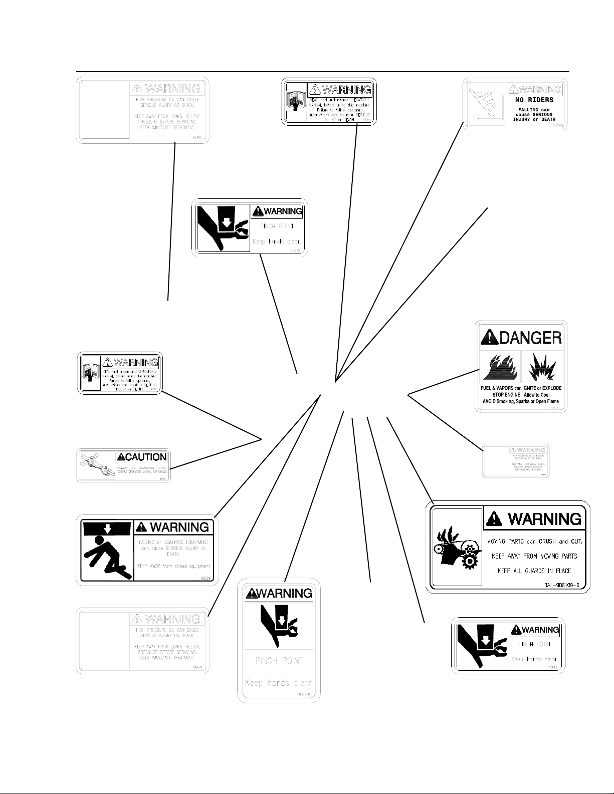
SAFETY DECALS ..................................................7
SAFETY
FOLLOW SAFETY INSTRUCTIONS ..............8
BEFORE OPERATING OR SERVICING........ 8
DURING OPERATION..................................... 9
BEFORE TRANSPORTING.............................9
DURING TRANSPORT..................................10
PRESSURIZED OIL ......................................10
PREPARING FOR EMERGENCIES ............. 11
WEARING PROTECTIVE EQUIPMENT ....... 11
SECTION I - OPERATIONS
PREPARING TOWING VEHICLE .......................1-1
PREPARING IMPLEMENT..................................1-1
HYDRAULICS ...............................................1-1
LUBRICATION ..............................................1-1
TIRES/WHEELS............................................1-1
CONNECTING SEED RUNNER TO
TOWING VEHICLE ......................................1-2
TRANSPORT CHAINS ........................................1-2
TRANSPORTING.................................................1-2
HYDRAULIC POWER UNIT OPERATION.........1-4
HYDRAULIC PRESSURE RELIEF VALVE ........1-5
PIVOTING CONVEYOR SIDE-TO-SIDE ............1-6
RAISING AND LOWERING CONVEYOR ..........1-6
FILLING PLANTER OR DRILL ..........................1-7
FILLING SEED TENDER FROM ANOTHER
WAGON OR BULK CONTAINER
(SELF-FILLING) ............................................1-8
LADDER ..............................................................1-9
TARP..................................................................1-10
UM 2410 & UM 2510 ELECTRONIC SCALE 1-11
BASIC OPERATION................................... 1-11
DETAILED PROCEDURE........................... 1-11
DOWNLOADER MODULE (OPT.) .............1-14
OPTIONAL AUTO-SHUTDOWN FEATURE
FOR UM 2510 SCALE ONLY...................1-15
OPTIONAL LIGHT KIT .....................................1-15
SECTION II - SERVICE
LUBRICATION .....................................................2-1
CONVEYOR BEARINGS..............................2-1
PIVOT POINTS ............................................2-1
WHEEL BEARINGS .....................................2-1
HYDRAULIC POWER UNIT ........................2-1
HYDRAULIC SYSTEM ........................................2-2
PURGE HYDRAULIC SYSTEM...................2-2
RELIEVING HYDRAULIC PRESSURE........2-2
CONVEYOR BELT ..............................................2-3
BELT TENSION............................................2-3
BELT TRACKING .........................................2-3
BRAKE CLEANING AND INSPECTION ............2-5
BRAKE LUBRICATION .......................................2-5
MAGNETS ...........................................................2-5
SHOE & LININGS ..............................................2-5
HOW TO MEASURE VOLTAGE ........................2-6
HOW TO MEASURE AMPERAGE.....................2-6
BRAKE DRUM INSPECTION.............................2-7
BEARING INSPECTION .....................................2-7
BEARING LUBRICATION....................................2-7
TROUBLESHOOTING BRAKES .........................2-7
POWER PAK.......................................................2-8
WHEEL TORQUE CHART &
TIRE SPECIFICATIONS.............................2-10
TORQUE CHART.............................................. 2-11
STORAGE.......................................................... 2-11
TROUBLE SHOOTING .....................................2-12
MASTER DISCONNECT SWITCH
ELECTRICAL SCHEMATIC ........................2-14
FRONT TRAILER
ELECTRICAL SCHEMATIC ........................2-15
TRAILER LIGHTING & BRAKE
ELECTRICAL SCHEMATIC ........................2-16
SEED TANK LIGHTING
ELECTRICAL SCHEMATIC ........................2-17
(March 2013)

5
TABLE OF CONTENTS
SECTION III - ASSEMBLY
SEED TENDER ASSEMBLY ..............................3-1
ASSEMBLY HITCH
TO UNDERCARRIAGE .................................3-1
ASSEMBLING SEED TENDER BOX
TO UNDERCARRIAGE .................................3-2
LADDER INSTALLATION ....................................3-3
ASSEMBLE CONVEYOR
TO PIVOT ARM ............................................3-4
HYDRAULIC DIAGRAM ......................................3-5
OPTIONAL SCALE PACKAGE...........................3-6
OPTIONAL AUTO-SHUTDOWN FEATURE
FOR UM 2510 SCALE ONLY......................3-7
OPTIONAL BELT STRETCHER .......................3-10
OPTIONAL ELECTRONIC ON/OFF VALVE.....3-12
OPTIONAL DISCHARGE SPOUT ....................3-14
OPTIONAL LIGHT KIT .....................................3-15
SECTION IV - PARTS
BOX DECAL & SERVICE PAINT ......................4-2
LADDER COMPONENTS ...................................4-4
DOOR, WINDOW, PIVOT COMPONENTS........4-6
PIVOT ARM COMPONENTS..............................4-8
HOPPER COMPONENTS
FOR 6” CONVEYOR TUBE .............................4-10
FOR 8” CONVEYOR TUBE .............................4-12
IDLER END COMPONENTS
FOR 6” CONVEYOR TUBE .............................4-14
FOR 8” CONVEYOR TUBE .............................4-16
DISCHARGE SPOUT COMPONENTS
FOR 6” CONVEYOR TUBE .............................4-18
FOR 8” CONVEYOR TUBE .............................4-20
HYDRAULIC COMPONENTS ...........................4-22
POWER PAK COMPONENTS..........................4-24
BOX ELECTRICAL COMPONENTS.................4-26
MASTER KEYSWITCH COMPONENTS ..........4-27
CABLE RETURN TARP COMPONENTS.........4-28
UNDERCARRIAGE
HITCH COMPONENTS ...............................4-30
UNDERCARRIAGE
FRAME COMPONENTS .............................4-31
UNDERCARRIAGE
FENDER COMPONENTS ...........................4-32
AXLE & WHEEL COMPONENTS ....................4-34
UNDERCARRIAGE
ELECTRICAL COMPONENTS ....................4-36
ELECTRIC BREAKAWAY
COMPONENTS............................................4-37
OPT ELECTRONIC ON/OFF CONTROL.........4-38
OPT TELESCOPIC SPOUT .............................4-38
OPT HOPPER COVER ....................................4-38
OPT SCALE COMPONENTS ...........................4-39
OPTIONAL LIGHT KIT .....................................4-40
OPTIONAL AUTO-SHUTDOWN KIT ................4-41

6
No accident-prevention program can be successful without the wholehearted cooperation of the person
who is directly responsible for the operation of the equipment.
A large number of accidents can be prevented only by the operator anticipating the result before the
accident is caused and doing something about it. No power-driven equipment, whether it be trans-
portation or processing, whether it be on the highway, in the harvest eld, or in the industrial plant,
can be safer than the person who is at the controls. If accidents are to be prevented--and they
can be prevented--it will be done by the operators who accept the full measure of their responsibility.
It is true that the designer, the manufacturer, and the safety engineer can help; and they will help,
but their combined efforts can be wiped out by a single careless act of the operator.
It is said that, “the best kind of a safety device is a careful operator.” We, at Unverferth Mfg. Co.,
Inc. ask that you be that kind of operator.
REMEMBER:
THINK SAFETY
A CAREFUL OPERATOR IS THE
BEST INSURANCE AGAINST AN
ACCIDENT!
SIGNAL WORDS
INDICATES AN EXTREMELY HAZARDOUS SITUATION OR ACTION THAT WILL RESULT
IN SERIOUS INJURY OR DEATH.
INDICATES A HAZARDOUS SITUATION OR ACTION THAT COULD RESULT IN SERI-
OUS INJURY OR DEATH.
INDICATES AN UNSAFE SITUATION OR ACTION THAT MAY RESULT IN PERSONAL
INJURY.
Is used for instruction on operating, adjusting, or servicing a machine.
GENERAL HAzARD INFORMATION
(March 2013)

7
SAFETY DECALS
Part No. 95445
Part No. 97961 Part No. 98350
Part No. 901580
Part No. 95839
Part No. 98229
Part No. 97048
Part No. 97961
Part No. 95445 Part No. 95839
Part No. 235161
Part No. 95445
Part No. TA1-906109-0
Part No. 97575
Part No. 902026
(March 2013)

8
SAFETY
• Read and understand this operator’s manual, and the towing vehicle’s operator’s
manual, before operating.
• All machinery should be operated only by trained and authorized personnel.
• To prevent machine damage, use only attachments and service parts approved by
the manufacturer.
• Always shut power unit and towing vehicle engine off and remove key before
servicing the Seed Runner.
• Avoid personal attire such as loose tting clothing, shoestrings, drawstrings, pants
cuffs, long hair, etc., that may become entangled in moving parts.
• Do not allow anyone to ride on the implement. Make sure everyone is clear before
operating.
FOLLOwING SAFETY INSTRUCTIONS
• Avoid working under the unit; however, if it becomes absolutely unavoidable, make
sure the implement is safely blocked.
• Always make certain everyone and everything is clear of the machine before
beginning operation.
• Turn engine off and remove key from ignition before servicing or adjusting
equipment.
• Verify that all safety shields are in place and secured.
• Ensure that all applicable safety decals are installed and legible.
• Explosive gas from the battery can cause res and severe acid burns. Charge the
battery only in a well ventilated area. Keep sources of ignition away.
• Explosive separation of a tire and rim can cause serious injury or death. Only properly trained
personnel should attempt to service a tire and wheel assembly.
BEFORE OPERATING OR SERVICING
(March 2013)

9
• Secure transport chains to Seed Runner and to towing vehicle before transporting.
DO NOT transport without chains.
• Install transport locks before transporting.
• Check that the brake controller is energized.
• Comply with state and local laws governing highway safety when moving
machinery.
• Use approved accessory lights, reectors and devices when transporting at night
and during periods of poor visibility.
SAFETY
• Regulate speed to eld conditions. Maintain complete control at all times.
• Never lubricate equipment when in operation.
• Carbon monoxide can cause severe nausea, fainting or death. Do not operate engine in
closed or conned area.
• Explosive fuel can cause res and severe burns. Stop engine before lling fuel tank.
• Hot parts can cause severe burns. Do not touch engine while operating or just after stopping.
• Seed being transported may contain seed treatment. Read and follow all requirements for
personal protective equipment and rst aid as outlined on seed tags.
• Keep away from overhead power lines. Electrical shock can cause serious injury
or death.
• Do not attempt to move any objects away from moving parts.
• Use extreme care when operating close to ditches, fences, or on hillsides.
• Do not leave towing vehicle or Seed Runner unattended with engine running.
DURING OPERATION
BEFORE TRANSPORTING
(March 2013)

10
• Relieve pressure before disconnecting hydraulic lines or servicing hydraulic system. See the
Maintenance section of this manual for the procedure to relieve pressure.
• Use a piece of cardboard or wood to detect leaks of hydraulic uid under pressure. Correct
hydraulic leaks immediately.
• High-pressure uids can penetrate the skin and cause serious injury or death.
Seek medical treatment immediately if injured by high-pressure uids.
• Never loosen or remove any hydraulic tting without rst verifying that all uid pressure has
been relieved. Failure to do so may result in unintended movement of all or a portion of the
equipment, possibly causing severe injury or death due to crushing or cutting. Injury may also
occur from contact with oil under pressure that may escape during tting removal.
• Hydraulic system must be purged of air before operating to prevent serious injury or death.
• Do not bend or strike high-pressure lines. Do not install bent or damaged tubes or hoses.
• Repair all oil leaks. Leaks can cause res, personal injury, and environmental damage.
• Route hoses and lines carefully to prevent premature failure due to kinking and rubbing against
other parts. Make sure that all clamps, guards and shields are installed correctly.
• Do not relieve hydraulic system pressure by loosening a tting.
• Tighten all connections before applying pressure. Keep hands and body away from hydraulic
leaks which eject uid under high pressure.
• Check hydraulic hoses and tubes carefully. Replace components as necessary if any of the
following conditions are found:
- End fittings damaged, displaced, or leaking.
- Outer covering chafed or cut and wire reinforcing exposed.
- Outer covering ballooning locally.
- Evidence of kinking or crushing of the flexible part of a hose.
- Armoring embedded in the outer cover.
• Use good judgment when transporting equipment on highways. Regulate speed
to road conditions and maintain complete control.
• Maximum speed of implement should never exceed 20 mph. Do not exceed 10
mph during off-highway travel.
• Slow down before making sharp turns to avoid tipping. Drive slowly over rough
ground and side slopes.
• Do not transport unit with rear compartment full and front compartment empty. The
unit may not be properly balanced, offsetting the trail ability of the Seed Runner.
DURING TRANSPORT
SAFETY
PRESSURIzED OIL
(March 2013)

11
• Wear clothing and personal protective equipment appropriate for the job.
• Wear steel-toed shoes when operating.
• Wear hearing protection when exposed to loud noises.
• Do not wear additional hearing impairing devices such as radio headphones, etc.
• Keep a rst aid kit and properly rated re extinguisher nearby.
• Keep emergency numbers for fire, rescue, and poison control personnel near the phone.
PREPARING FOR EMERGENCIES
• This product may contain a chemical known to the state of California to cause cancer, or birth
defects, or other reproductive harm.
wEARING PROTECTIVE EqUIPMENT
SAFETY
(March 2013)

12
NOTES
(March 2013)

1-1
Operation
Before operating implement, refer to towing
vehicle’s operator’s manual for information
concerning safe methods of operation, hitch
capacities, hitch adjustments, tire inflation, and
undercarriage braking operation.
Vehicle must be equipped with proper electric
undercarriage braking components. Check vehicle
brakes and warning lights. Make sure they are
in proper working order.
IMPORTANT: This implement is equipped with
LED lights. The towing vehicle may require a
flasher upgrade for lights to function properly.
For flasher upgrade, please see towing vehicle
manufacturer for assistance.
Do not exceed towing vehicle’s GVWR (Gross
Vehicle Weight Rating) or GCWR (Gross Com-
bination Weight Rating), or the maximum hitch
load.
PREPARING IMPLEMENT
SECTION I
OPERATIONS
PREPARING TOWING VEHICLE
Estimated weights of the fully loaded Seed
Runner are:
Model 3750
Gross Vehicle Weight Rating is 25,000 lbs.
Loaded tongue weight is 1000 lbs.
Model 2750
Gross Vehicle Weight Rating is 19,500 lbs.
Loaded tongue weight is 1000 lbs.
These are estimates. The loaded tongue weight
will vary greatly based on the height of the
hitch, and the variation in terrain that the Seed
Runner is being pulled across.
Towing vehicle hitch – ball or pintle hook, must
be heavy enough to carry the load of the Seed
Runner.
HYDRAULICS
Check routing of all hydraulic hoses. Hoses
should not be kinked, twisted, or rubbing against
sharp edges.
Check hoses and fittings for hydraulic leaks.
Tighten and/or repair or replace as required.
Refer to “Torque Chart” in SERVICE section.
LUBRICATION
Lubricate as outlined in SERVICE section.
Refer to this operator’s manual for proper fluid
levels in engine.
TIRES/WHEELS
Check tire pressures and maintain at recom-
mended values listed in the "SERVICE" section
of this manual.
CAUTION! IMPROPERLY TORQUED
WHEEL NUTS/BOLTS CAN CAUSE A
LOSS OF IMPLEMENT CONTROL AND MA-
CHINE DAMAGE. WHEEL NUTS/BOLTS MUST
BE CHECKED REGULARLY. SEE TORQUE PAGE
IN THE "SERVICE" SECTION FOR PROPER
WHEEL NUT/BOLT SPECIFICATIONS. WARRANTY
DOES NOT COVER FAILURES CAUSED BY
IMPROPERLY TORQUED WHEEL NUTS/BOLTS.
For questions regarding new tire warranty, please
contact your local original equipment tire dealer.
Used tires carry no warranty. Tire manufactur-
ers' phone numbers and web sites are listed
in the "SERVICE" Section of this manual for
your convenience.

Operation
1-2
WARNING! DO NOT STAND BETWEEN
IMPLEMENT AND TOWING VEHICLE WHEN
HITCHING.
The Seed Runner Undercarriage is designed to
be connected to a towing vehicle utilizing either
the pintle hitch, or a 2 5/16” ball hitch.
Back the towing vehicle up to the undercar-
riage and align the vehicle’s ball or pintle hook
with the coupler or ring on the undercarriage.
Lower jack to set undercarriage down on ball
or pintle hook. Latch coupler so the connection
is secure. Pivot jack to transport position and
pin in place.
TRANSPORT CHAINS
Connect electrical plug from undercarriage to
towing vehicle. Check routing of the electrical
cord to be certain it is long enough to pivot
when turning, but not too long to touch or rub
the ground during transport.
Connect undercarriage brake breakaway cable
to towing vehicle. Do not connect this directly
to hitch. It needs to be connected in a place
that will still be attached, even if the ball or
pintle coupler fails.
CAUTION! ALWAYS USE TRANSPORT
CHAINS WHEN TRANSPORTING IMPLE-
MENTS. FAILURE TO USE CHAINS COULD
CAUSE PERSONAL INJURY OR DAMAGE IF
IMPLEMENTS BECOME DISENGAGED.
Transport chains should have a minimum rating
equal to the gross weight of implement and all
attachments. Allow no more slack in chains than
necessary to permit turning.
Cross chains when connecting as shown in
photo.
IMPORTANT: Replace transport chains if any link
or end fitting is broken, stretched, or damaged.
DO NOT WELD TRANSPORT CHAINS.
IMPORTANT: Before unit is transported, be sure
the jack stand is in the ‘Transport Position’.
TRANSPORTING
Transport Position
I
MPORTANT: Conveyor must be latched in the
unloading position. The pivoting arm must be
latched in the transport position with klik pin
installed before moving unit. Refer to photo on
following page.
WARNING! THE REAR HOPPER OF THE
SEED TENDER BOX SHOULD ALWAYS BE
EMPTIED FIRST. THIS WILL MAINTAIN WEIGHT
ON THE HITCH OF THE TOWING VEHICLE.
EMPTYING THE FRONT HOPPER FIRST WITH
THE REAR HOPPER FULL COULD RESULT IN
NEGATIVE TONGUE WEIGHT ON THE UNDER-
CARRIAGE AND REDUCED CONTROL OF THE
UNDERCARRIAGE WHEN TOWING.
CONNECTING SEED RUNNER TO TOWING VEHICLE

1-3
Operation
CAUTION! USE APPROVED ACCES-
SORY LIGHTS, REFLECTORS, AND DE-
VICES WHEN TRANSPORTING AT NIGHT AND
DURING PERIODS OF POOR VISIBILITY.
WARNING! ALWAYS TRAVEL AT A
SPEED THAT PERMITS COMPLETE CON-
TROL OF TOWING VEHICLE AND IMPLEMENT.
DANGER! CONTACT WITH UTILITY LINES
CAN CAUSE SERIOUS INJURY OR DEATH.
DO NOT OPERATE SEED RUNNER NEAR UTIL-
ITY LINES.
Conveyor Latch
Pivot Latch
Transport Latch
When transporting on public roads, the conveyor
needs to be latched in the forward position,
extending over the tongue of the undercarriage.
Transporting implement with conveyor latched
in the rearward position does not comply with
lighting and conspicuity marking requirements.
The center of gravity on the seed tender box
is higher than a typical undercarriage. Use
extreme caution when making turns and enter-
ing/exiting fields.
Comply with all state and local laws governing
highway safety and regulation when moving
machinery on public roads.
Be sure reflectors and lights are in place and
clearly visible to approaching traffic.
IMPORTANT: This implement is equipped with
LED lights. The towing vehicle may require a
flasher upgrade for lights to function properly.
For flasher upgrade, please see towing vehicle
manufacturer for assistance.
Be certain clearance to rafters, walls, machin-
ery, etc. exists before operating conveyor. With
a towing vehicle hooked to the Seed Runner,
activate the belt to make sure everything moves
freely. Do not pinch or kink hoses.

Operation
1-4
NOTE: Installation instructions for the spark
arrestor can be found in the Honda engine
manual.
BEFORE STARTING ENGINE:
Inspect that all fittings and hardware are in
place and secure. Check for any potential hy-
draulic leaks. Check fluid levels in engine and
sight gauge on reservoir. Be sure all valves are
switched to neutral position.
STARTING ENGINE:
Turn fuel shut-off valve to <ON> position. Ap-
ply choke, and turn key or pull recoil rope to
start engine. The “Master Key” switch replaces
the standard ignition switch which is no longer
functional. Once running, turn choke off and
increase throttle speed.
In extremely cold weather, it is best to allow
engine and hydraulics to warm up before op-
erating at full throttle speed.
NOTE: If hydraulic leaks become apparent, turn
engine OFF immediately and take appropriate
actions.
See Engine operator’s manual for more detailed
information on engine operation.
WARNING! EXPLOSIVE FUEL CAN CAUSE
FIRES AND SEVERE BURNS. STOP EN-
GINE BEFORE FILLING FUEL TANK.
WARNING! CARBON MONOXIDE
CAN CAUSE SEVERE NAUSEA, FAINTING
OR DEATH. DO NOT OPERATE ENGINE IN A
CLOSED OR CONFINED AREA.
WARNING! HOT PARTS CAN CAUSE
SEVERE BURNS. DO NOT TOUCH ENGINE
WHILE OPERATING OR JUST AFTER STOP-
PING.
WARNING! EXPLOSIVE GAS FROM
BATTERY CAN CAUSE FIRES AND SE-
VERE ACID BURNS. CHARGE BATTERY ONLY
IN A WELL VENTILATED AREA. KEEP SOURCES
OF IGNITION AWAY.
WARNING! HYDRAULIC SYSTEM MUST
BE PURGED OF AIR BEFORE OPERATING
TO PREVENT SERIOUS INJURY OR DEATH.
WARNING! HIGH-PRESSURE FLUIDS
CAN PENETRATE THE SKIN AND CAUSE
SERIOUS INJURY OR DEATH. SEEK MEDICAL
TREATMENT IMMEDIATELY IF INJURED BY HIGH-
PRESSURE FLUIDS. USE CARDBOARD OR WOOD
TO DETECT LEAKS IN THE HYDRAULIC SYSTEM.
HYDRAULIC POWER UNIT OPERATION
WARNING! RELIEVE HYDRAULIC PRES-
SURE BEFORE SERVICING HYDRAULIC
SYSTEM. SEE “ADJUSTING HYDRAULIC PRES-
SURE RELIEF VALVE” IN OPERATIONS SECTION
OF THIS MANUAL.
IMPORTANT: Make certain hoses are all con-
nected, and everyone is clear of conveyor before
starting engine.
IMPORTANT: Conveyor must be turned off before
starting engine. Starting engine with conveyor
turned on will result in hard starting, or failure
to start.
IMPORTANT: When engine is not in use, turn
fuel lever to the <OFF> position. Leaving the fuel
valve on could cause carburetor flooding, fuel in
crankcase, or fuel leakage. See photo above.
WARNING! OPERATION OF THIS EQUIP-
MENT MAY CREATE SPARKS THAT CAN
START FIRES AROUND DRY VEGETATION. A
SPARK ARRESTOR MAY BE REQUIRED. THE OP-
ERATOR SHOULD CONTACT LOCAL FIRE AGEN-
CIES FOR LAWS OR REGULATIONS RELATING
TO FIRE PREVENTION REQUIREMENTS. THE
Fuel Shut-Off
Key
Choke
Throttle
SPARK ARRESTOR MUST BE PURCHASED SEP-
ARATELY AND CAN BE FOUND IN THE PARTS
SECTION NEAR THE END OF THIS MANUAL.
Revised 082310-1

1-5
Operation
ADJUSTING HYDRAULIC PRESSURE
RELIEF VALVE:
a. This unit has an adjustable relief valve
which can be adjusted for optimum op-
eration. It is pre-set at the factory to by-
pass the system once the hydraulic fluid
pressure exceeds 1500 psi. This is the
optimum setting for this unit. Adjusting
the relief to higher settings may give un-
satisfactory results.
IMPORTANT: This unit can be adjusted to pro-
vide system pressures from 1,000 PSI up to
2500 PSI. When adjusting the relief to allow
the system to exceed 1500 PSI, the engine
will tend to bog down due to the load and in
high load applications, may cause the engine
to stall.
b. Remove the Pump Cover by loosening
the hex capscrew and lock washer se-
curing it.
1 1/8” Wrench
Mark position of 1,500
psi setting for reference
!
"
#$
Decrease
Pressure
Increase
Pressure
5/16” Allen Wrench
c. Remove the relief adjustment cover by
using two wrenches, 1 1/8” and a 1”.
d. Mark the location of the set screw in re-
lationship to the valve to know where the
1,500 psi setting is, with a paint pen or
permanent marker.
e. With the 1 1/8” wrench and a 5/16” Allen
wrench, loosen jam nut securing the ad-
justment screw.
f. Looking at the head of the adjustment
screw. Rotate clockwise to increase relief
pressure, counter-clockwise to decrease
as shown.
IMPORTANT: It will be necessary to install a
pressure gauge into the hydraulic system to
accurately adjust the relief valve.
g. Once desired setting is reached. Be sure
to lock down adjustment screw with jam
nut and replace the washer and adjust-
ment screw cap. Replace and tighten
pump cover.
1” Wrench
Pressure Relief
Valve
Remove Pump
Cover

Operation
1-6
Remove klik pin from pivot transport lock. Start
engine on hydraulic power unit and increase
throttle speed to wide open. Operate hydraulic
valve to raise conveyor so that it clears transport
cradle. Turn lever to release pivot latch, and
swing conveyor out to desired position.
Conveyor pivot can be left to swing freely, or
it can be latched in place at various points
along the track.
IMPORTANT: Use caution when parking on in-
clines. Conveyor may pivot on its own as soon
as latch is released!
Pivot Latch
Valve Control Lever
Transport Latch Klik Pin
Conveyor height is adjusted by the use of a
spool valve that actuates the cylinder on the
pivoting arm.
IMPORTANT: Always remove klik pin from pivot
transport lock before raising conveyor.
Activate valve to raise or lower conveyor to
desired height. A check valve in the system
requires hydraulic pressure for both raising and
lowering the conveyor.
PIVOTING CONVEYOR SIDE-TO-SIDE
RAISING AND LOWERING CONVEYOR

1-7
Operation
Position the seed tender next to planter so con-
veyor discharge will be over planter box. Start
engine on hydraulic power unit and increase
throttle speed. Raise conveyor to desired dis-
charge height, and pivot to location over planter.
Place telescoping spout over planter box. Open
door(s) on seed tender box to begin flow of
seed. Turn on conveyor by either sliding manual
control lever or activating electric on/off switch
to on position.
Fill box to desired level, and turn conveyor off.
Repeat process until each box/hopper is filled.
Adjusting engine speed on the hydraulic power
unit can regulate conveyor speed.
IMPORTANT: Do not let telescoping spout rest
in bottom of seed box. Seed will rapidly build
up and plug conveyor, resulting in potential
damage to belt.
It is recommended that the conveyor be emptied
once planter is filled. Do this by closing door(s)
on seed tender box shortly before last planter
box is full, and let conveyor empty out.
Control Rod
NOTE: When using the 8” conveyor to fill indi-
vidual planter boxes, the cover plate must be
installed over grate. This will slow grain flow
to an acceptable level for ease of use. Failure
to do so will result in over-filling conveyor and
potential damage to seed or conveyor.
Leaving seed in the conveyor for short periods
of time will not damage conveyor, nor will it
hinder starting/stopping conveyor when it is full,
but over time seed could begin to settle result-
ing in hard starting of the conveyor.
WARNING! THE REAR HOPPER OF THE
SEED TENDER BOX SHOULD ALWAYS
BE EMPTIED FIRST. THIS WILL MAINTAIN
WEIGHT ON THE HITCH OF THE TOWING VE-
HICLE. EMPTYING THE FRONT HOPPER FIRST
WITH THE REAR HOPPER FULL COULD RE-
SULT IN NEGATIVE TONGUE WEIGHT ON THE
UNDERCARRIAGE AND REDUCED CONTROL
OF THE UNDERCARRIAGE WHEN TOWING.
FILLING PLANTER OR DRILL

Operation
1-8
FILLING SEED TENDER FROM ANOTHER WAGON OR
BULK CONTAINER (SELF-FILLING)
WARNING! THE SEED RUNNER MUST
BE HOOKED TO THE TOWING VEHICLE
WHEN BEING FILLED AND THE BRAKES ON
THE TOWING VEHICLE MUST BE SET.
WARNING! FILL THE FRONT
COMPARTMENT OF THE SEED RUNNER
FIRST BEFORE THE REAR COMPARTMENT TO
HELP PREVENT INSTABILITY OF SEED RUN-
NER.
Pivot conveyor out of transport position and
lower completely. Remove upper spout from
conveyor by releasing latch and sliding spout off
of conveyor. Loosen the two knobs on the side
of the deflector, pivot deflector up, and tighten
knobs to hold deflector in place.
Position conveyor so that the discharge end
is located over the seed tender box and the
hopper is on the ground or on the stand away
from the box.
Raise conveyor about half way up. Unlatch
conveyor from lower cradle, lower flexible hop-
per by sliding lever back, and pull hopper end
of conveyor out from under the seed tender
box.
IMPORTANT: Whenever possible, use the stand
on the bottom of the conveyor to keep the
hopper off the ground. Maximum conveyor per-
formance and easier access to discharge point
on bulk seed containers will result.
Conveyor Latch
Hopper Raise/Lower
Loosen knobs
to pivot defl ector
This manual suits for next models
1
Table of contents
Popular Farm Equipment manuals by other brands

Galebreaker
Galebreaker Bayscreen Installation and operating instructions

Raven
Raven SmarTrax installation manual

Amadas
Amadas SPC-4 instruction manual

InterPuls
InterPuls Combifast Instruction Manual, Operation and Maintenance original instructions

Quattro
Quattro Titanium EGO400 Installation guide and user information

RainFlo
RainFlo 480 operating manual