Gateway 210 Guide
ISSUED: 04-21-03 SHEET #: 055-9158-1
1 of 8
Visit the Peerless Web Site at www.peerlessindustries.com For customer service call 1-800-729-0307 or 708-865-8870.
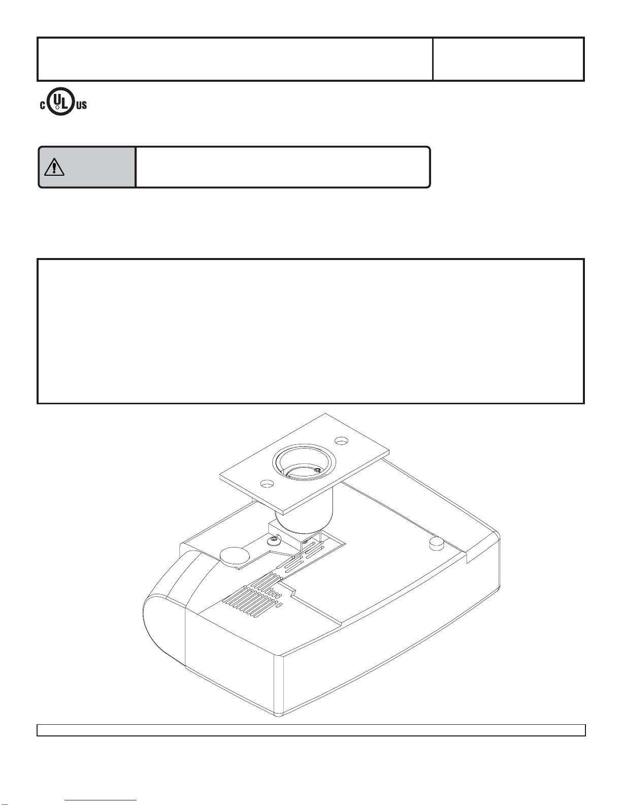
Read instruction sheet before you start installation and assembly.
Maximum Load Capacity: 20 lb (9.1 kg)
Installermustverifythat theceiling willsafely support
thecombinedweight ofprojectormountandprojector.
WARNING
IMPORTANT! Be sure not to touch the projector while tightening the set screw on the
ball and socket mount. This may cause the image to be unaligned when you let go.
Installation and Assembly - Security Projector Mount
for Gateway™ 210 Projector
R
Three Different Applications:
FlushMount..................................................................................................................................... step 3, page 5
Threaded Rod ..................................................................................................................................step 4, page 5
ExtensionColumn........................................................................................................................................ page 6
InstallationConditions:
To Wood Joist Finished Ceilings,
Exposed Wood Joists, or Wood Beam Ceilings........................................................................................ page 3
To Concrete Ceilings.................................................................................................................................... page 4
IMPORTANT! Turn to the appropriate page for your application and ceiling condition.
This product is intended for use with UL
Listed products and must be installed
by a qualified professional installer.
Model: PJ-G210
Reference Gateway 8007000
ISSUED: 04-21-03 SHEET #: 055-9158-1
2 of 8
Visit the Peerless Web Site at www.peerlessindustries.com For customer service call 1-800-729-0307 or 708-865-8870.
B
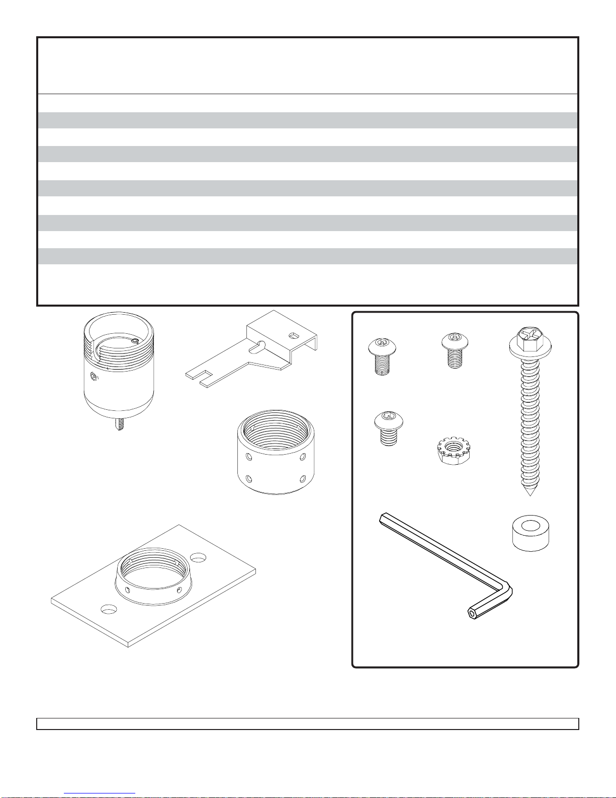
Parts List
Before you start check the parts list to insure all of the parts shown are included.
E
A
D
G
F
H
Description Qty. Part Number
Aball and socket assembly 1 055-0365
B4 mm security allen wrench 1 560-9646
CM5 x .8 x 10 mm socket pin type F screw 1 520-1164
D1/4- 20 x 3/8 socket pin screw 1 520-1109
E1/4- 20 x 3/8 nut 1 530-9303
F#14 x 2.5 phillips hex head wood screw 2 5S1-015-C03
Gceilingplate 1 142-1006
H.25" ID x .56" OD x .26 spacer 2 590-1050
Iextensioncolumn connector 1 580-1013
J10-32 x 3/8socket pin screw 2 520-1084
Kbracket 1 055-1366
I
Note: Actual parts may appear slightly different than illustrated.
J
FASTENERS
K
C
For Missing Parts, contact customer service at 1-800-729-0307.
ISSUED: 04-21-03 SHEET #: 055-9158-1
3 of 8
Visit the Peerless Web Site at www.peerlessindustries.com For customer service call 1-800-729-0307 or 708-865-8870.
F
F
G
WOOD
JOIST
CEILING
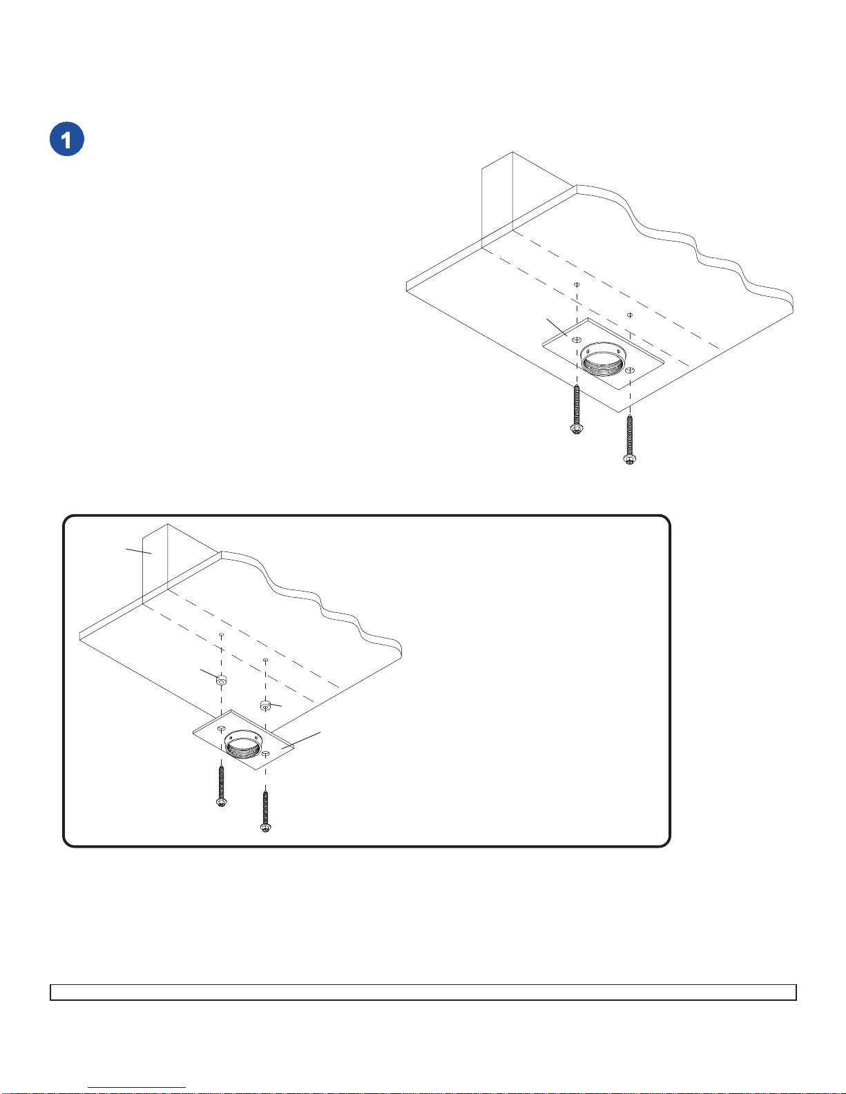
Drill two 5/32" (4 mm) dia. holes to a minimum
depth of 2.5" (64 mm). Attach ceiling plate (G)
with two #14 x 2.5" (6 mm x 65 mm) wood
screws (F) as shown using 3/8" (10 mm) socket
wrench.Tighten wood screws(F) soceiling
plate (G) is firmly attached.
DONOT TIGHTEN WITH EXCESSIVE FORCE!
Overtighteningcancause stressdamageto
woodscrews(F)greatlyreducingtheirholding
power! Tighten to 80 in • lb (9 N.M.) maximum
torque.
WARNING: It is the responsibility of the
installer to verify that the ceiling will safely
support the combined load of all attached
hardware and components.
IMPORTANT: Be sure to drill holes into the
joist CENTER!
For optional Cord Management,
installtwo spacers (H) between ceiling
plate(G)and ceiling.
Installation To Wood Joist Finished Ceilings,
Exposed Wood Joists, or Wood Beam Ceilings
WOOD
JOIST
CEILING
F
F
G
HH
ISSUED: 04-21-03 SHEET #: 055-9158-1
4 of 8
Visit the Peerless Web Site at www.peerlessindustries.com For customer service call 1-800-729-0307 or 708-865-8870.
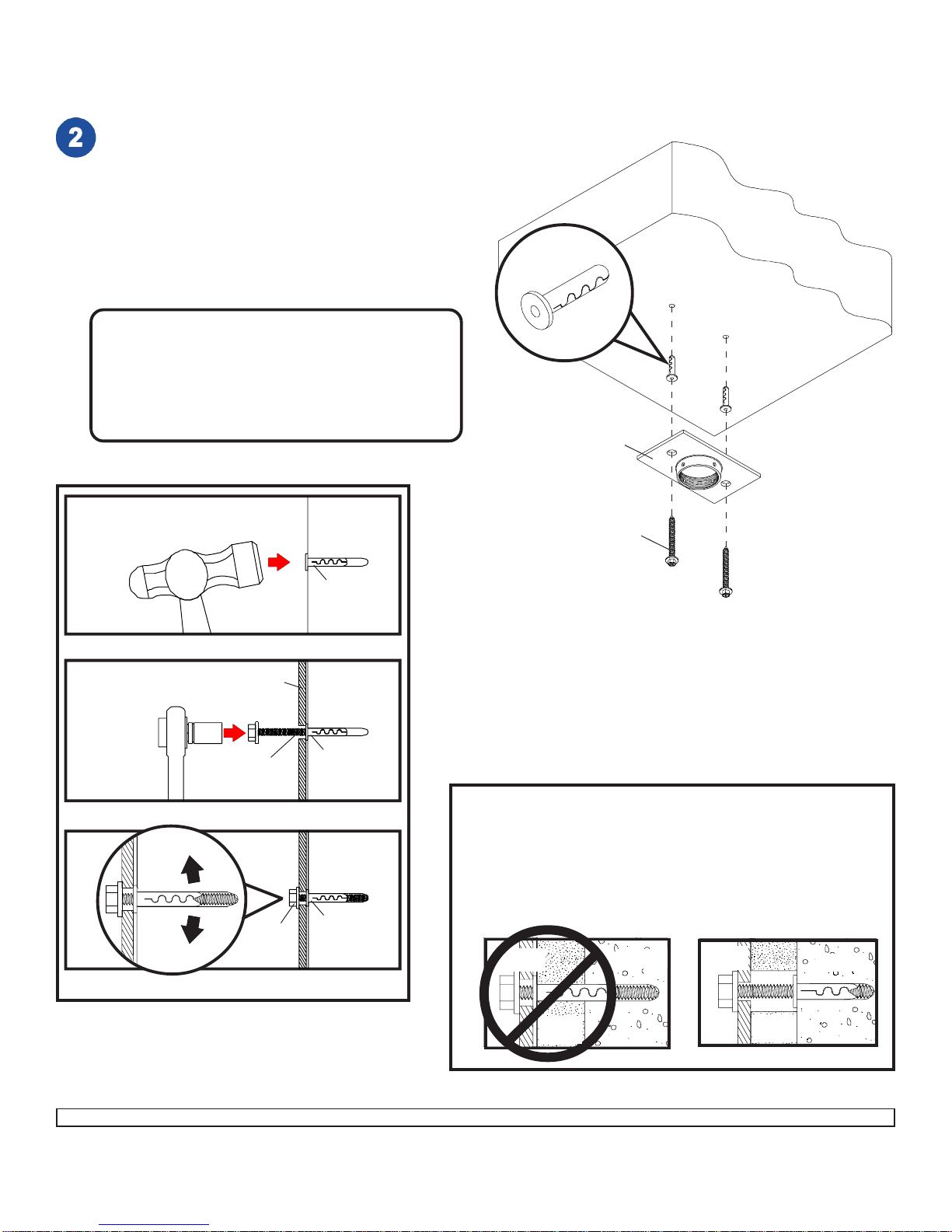
CAUTION: Tighten wood screws so ceiling plate
(G) is firmly attached. But DO NOT TIGHTEN
WITH EXCESSIVE FORCE! Overtightening can
cause stress damage to wood screws, greatly
reducing their holding power! Tighten to 80 in •
lb(9 N.M.) maximum torque.
Drill two 1/4" (6 mm) dia. holes to a minimum
depth of 2.5" (64 mm). Attach ceiling plate (G)
using two concrete anchors and #14 x 2.5" wood
screws (F) as shown in Illustration A and 1, 2,
and3(below).Tightenallfasteners.
IMPORTANT: It is the responsibility of the
installer to verify that the ceiling will safely
support the combined load of all attached
hardware and components.
1
3
Drill hole and insert anchor
Place ceiling plate over anchor and secure with screw
After repeating step one tighten all fasteners
CUTAWAYVIEW
INCORRECT
concrete
metal
bracket
plaster/
drywall
CORRECT
concrete
metal
bracket
plaster/
drywall
FORDIRECTATTACHMENT TO LOAD BEARING CONCRETE
ONLY! Concrete expansionanchors are not intendedfor
attachment to concrete ceilings covered with a layer of plaster,
drywall,or other finishing material.If mounting toconcrete
ceilingcovered with plaster /drywall is unavoidable,plaster/
drywallmust be counterboredas shown below.
concrete
ceiling
concrete
anchor
concrete
anchor
concrete
anchor
F
F
F
Illustration A
Installation to Concrete Ceilings
ACC 03 (Alligator® concrete anchors) are recommended.
concrete
anchor
G
2G
CONCRETECEILING
ISSUED: 04-21-03 SHEET #: 055-9158-1
5 of 8
Visit the Peerless Web Site at www.peerlessindustries.com For customer service call 1-800-729-0307 or 708-865-8870.
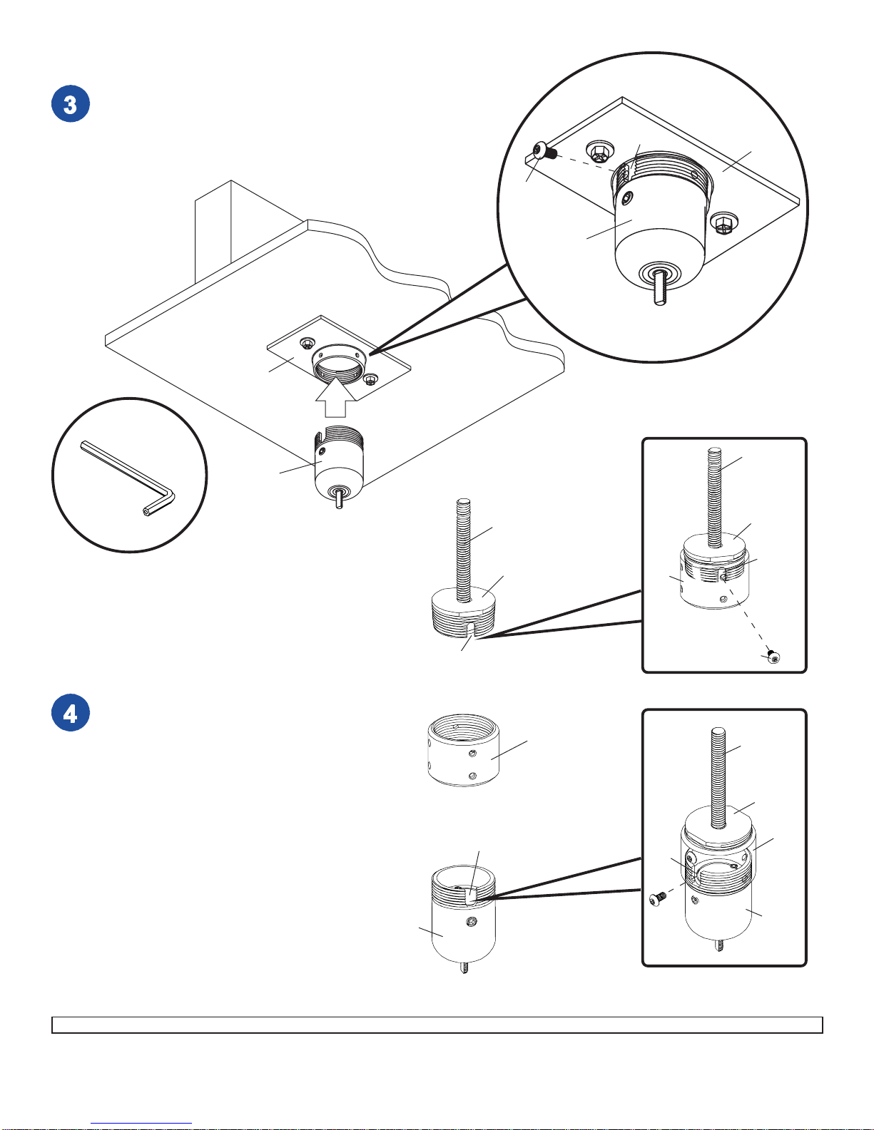
Screw ball and socket assembly (A) into ceiling plate (G). Align the
notch with one of the four holes of the ceiling plate (G) and secure
ball and socket assembly (A) with a M5 x 10 mm socket pin
screw (C) using security allen wrench (B) as shown in detail 1.
Skip to step 6.
DETAIL 1
A
G
A
C
WOOD
JOIST
CEILING
NOTCH G
Flush Mount Application
SLOT
SLOT
A
ACC 810
1/2-13THREADED ROD
ScrewACC 810 into extensioncolumn
connector (I). Align slot in ACC 810 with one of
the top holes in extension column connector (I).
Insert and tighten one 10-32 x 3/8socket pin
screw(J)throughextensioncolumnconnector
(I)into slot on ACC 810 using 4 mm security
allen wrench (B). See detail 2.
Align slot in ball and socket mount (A) to one of
the bottom holes in extension column connector
(I). Insert and tighten one 10-32 x 3/8socket pin
screw(J)throughextensioncolumnconnector
(I)into slot in ball and socket mount (A).
See detail 3.
Skip to step 6.
SLOT
DETAIL 2
ACC 810
THREADED
ROD
ACC 810
THREADED
ROD
DETAIL 3
A
I
I
I
J
J
Installation to
Threaded Rod
Accessory ACC 810, threaded rod adapter, is
required. (Sold Separately)
SLOT
B
ISSUED: 04-21-03 SHEET #: 055-9158-1
6 of 8
Visit the Peerless Web Site at www.peerlessindustries.com For customer service call 1-800-729-0307 or 708-865-8870.
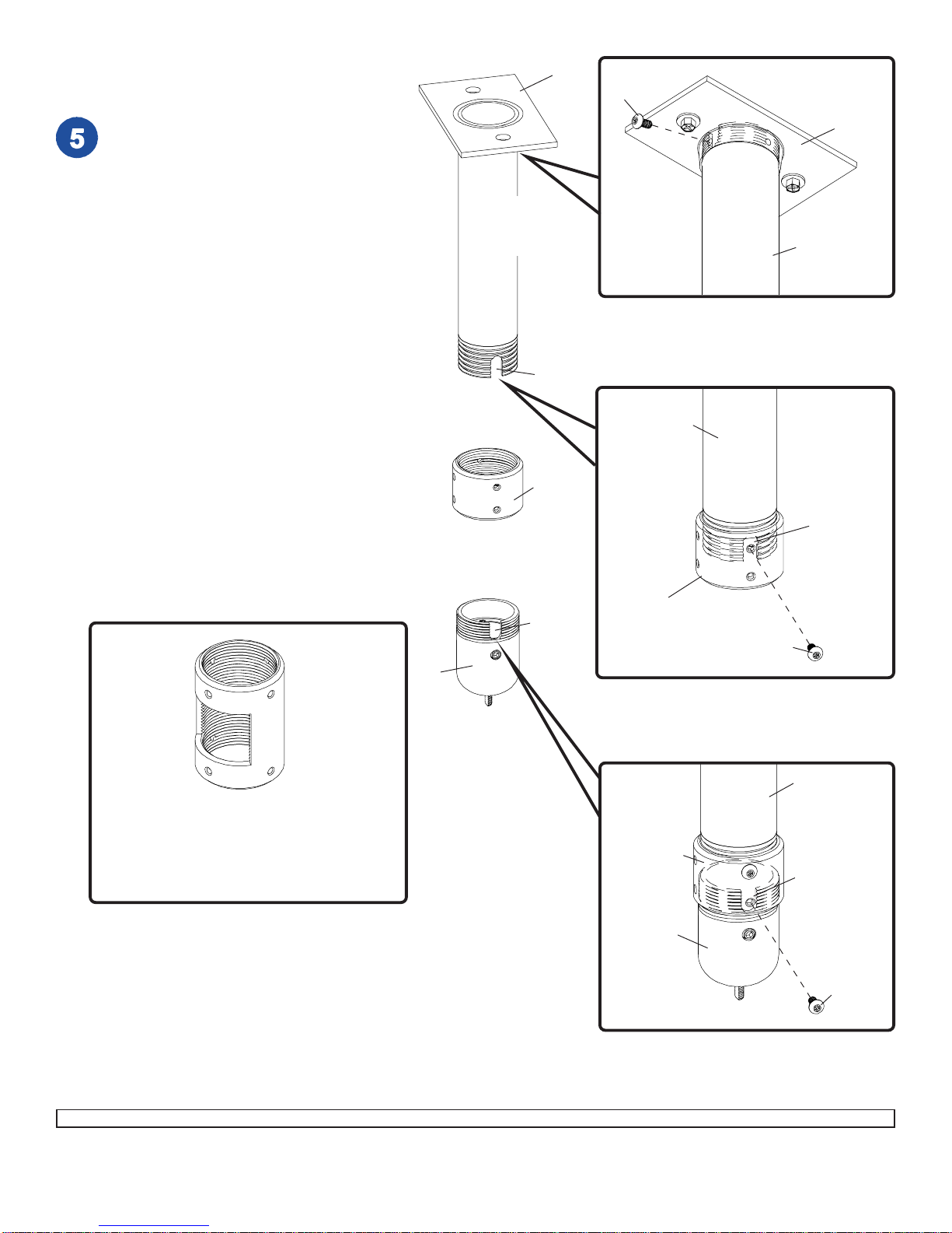
Screw extension column to ceiling plate (G).
Align the notch with one of the four holes in
the ceiling plate (G) and secure extension
column with a M5 x 10 mm socket pin
screw(C) usingsecurity allen wrench (B).
See detail 4.
Screw extension column connector (I) to
extension column. Align slot in extension
column with one of the top holes in
extensioncolumn connector(I).Insertand
tighten one 10-32 x 3/8socket pin screw (J)
throughextensioncolumn connector(I)into
slot on extension column using security
allen wrench (B). See detail 5.
Screw ball and socket mount (A) to
extension column connector (I). Align slot in
ball and socket mount (A) to one of the
bottom holes in extension column connector
(I). Insert and tighten one 10-32 x 3/8socket
pinscrew(J)through extensioncolumn
connector into slot in ball and socket mount
(A)using securityallen wrench(B).
See detail 6.
ACC 850 - EXTENSION COLUMN CONNECTOR
WITH CORD MANAGEMENT - MAY BE USED IN
PLACE OF EXTENSION COLUMN CONNECTOR (I).
THIS ALLOWS INSTALLER TO ROUTE CORDS UP
THROUGHTHE EXTENSION COLUMN.
(SOLD SEPARATELY)
DETAIL 6
A
EXTENSION
COLUMN
SLOT
I
J
A
SLOT
SLOT
EXTENSION
COLUMN(SOLD
SEPARATELY)
G
I
DETAIL 5
EXTENSION
COLUMN
SLOT
I
J
DETAIL 4
EXTENSION
COLUMN
CG
Installation to
Extension Column

ISSUED: 04-21-03 SHEET #: 055-9158-1
7 of 8
Visit the Peerless Web Site at www.peerlessindustries.com For customer service call 1-800-729-0307 or 708-865-8870.
To adjust roll, pitch, and yaw loosen the set screw
(shown below) using security allen wrench (B) or
standard 4 mm allen wrench. You should be able to
just slightly loosen the screw so that your adjustments
can be set without having to hold the projector. Move
projector to desired position and slowly tighten set
screw.
Note: Be sure not to touch the projector while
tightening the set screw. This may cause the image
to be unaligned when you let go.
IMPORTANT: Security allen wrench (B) is your key for
projector removal. Store it in a safe place.
©2003PeerlessIndustries,Inc.Allrightsreserved.
SETSCREW
Attach bracket (K) to ball and socket assembly (A)
using 1/4 - 20 nut (E).
Press button on side of projector to lift projector foot.
Slide bracket (K) under projector foot. Push foot
down. Secure bracket (K) with 1/4 - 20 socket pin
screw (D).
A
WOOD
JOIST
CEILING
PROJECTOR
WOOD
JOIST
CEILING
PROJECTOR
D
E
K
A
CUTAWAY VIEW OF
CEILINGPLATE (G)
K
PROJECTOR
FOOT

ISSUED: 04-21-03 SHEET #: 055-9158-1
8 of 8
Visit the Peerless Web Site at www.peerlessindustries.com For customer service call 1-800-729-0307 or 708-865-8870.
PEERLESSLIMITEDWARRANTY
Peerlesswarrantsitsproducts,undernormaluse,tobefreefromdefectsinmaterialandworkmanshipforaperiodoffiveyears
fromthedateofpurchase.Peerless,atitssolediscretion,willrepairorreplacesuchdefectiveequipmentfreeofchargeprovided
theproductsarereturnedprepaidtoPeerless.Thereafter,repairswillbemadeatestablishedfactoryprices.Unauthorizedservice
orrepairsbyanyoneotherthanauthorizedPeerlesspersonnelrendersthisWarrantyvoidandreleasesPeerlessfromanyfurther
responsibilityorobligation.Anydamagecausedbyfailuretoobserveproperpackingortoobserveinstructionsforinstallation,by
accidentorintransitorelsewherewillnotbecoveredbytheWarranty.ThisWarrantyisinlieuofallotherWarrantiesexpressed
orimplied,andnooneisauthorizedtoassumeanyliabilityonbehalfofPeerlessorimposeanyobligationonitinconnectionwith
thesaleofanyproductotherthanasoutlinedabove.Innoeventwillresponsibilitybeassumedorimpliedforconsequential
damagesarisingfromthetheftofanyproductsecuredbyaPeerlesssecuritydevice,bydelayofinstallation,interruptedoperation
orothercauses.
Other manuals for 210
2
This manual suits for next models
1
Table of contents


