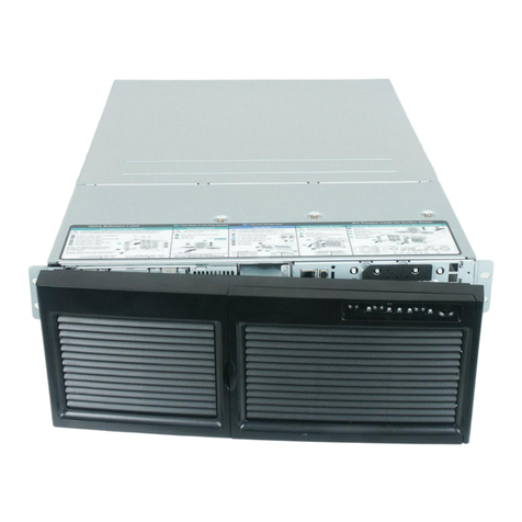
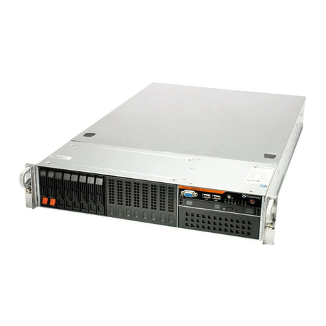
Gateway ALR 8200R User manual

GatewayALR
8200R
User’s Guide
Part #8502953 A MAN US GW2K 8200R USR GDE R0 6/98
In our effort to use nature’sresources efficiently and wisely, we print all manuals on recycled papers that meet the
minimum requirements established by the Federal EPA in itsguidelines for recycled paper products.
2953.book Page i Monday, June 15, 1998 11:27 AM

ii Gateway ALR 8200R User’s Guide
Notices
Copyright © 1998 Gateway 2000, Inc.
All Rights Reserved
610 Gateway Drive
N. Sioux City, SD 57049 USA
All Rights Reserved
This publication is protected by copyright and all rights are reserved. No part of it may be reproduced
or transmitted by any means or in any form, without prior consent in writing from Gateway 2000.
The information in this manual has been carefully checked and is believed to be accurate. However,
changes are made periodically. These changes are incorporated in newer publication editions.
Gateway2000 may improve and/or change products described in this publication at any time. Due to
continuing system improvements, Gateway 2000 is not responsible for inaccurate information which
may appear in this manual. For the latest product updates, consult the Gateway2000 web site at
www.gateway.com. In no event will Gateway 2000 be liable for direct, indirect, special, exemplary,
incidental, or consequential damages resulting from any defect or omission in this manual, even if
advised of the possibility of such damages.
In the interest of continued product development, Gateway 2000 reserves the right to make
improvements in this manual and the products it describes at any time, without notices or obligation.
Trademark Acknowledgments
AnyKey, black-and-white spot design, ColorBook, CrystalScan, Destination, EZ Pad, EZ Point, Field
Mouse, Gateway 2000, HandBook, Liberty, TelePath, Vivitron, stylized “G” design, and “You’ve got a
friend in the business” slogan are registered trademarks and “All the big trends start in South Dakota”
slogan, GATEWAY, and Gateway Solo are trademarks of Gateway 2000, Inc. Intel, Intel Inside logo,
and Pentium are registered trademarks and MMX is a trademark of Intel Corporation. Microsoft, MS,
MS-DOS, and Windows are trademarks or registered trademarks of Microsoft Corporation. All other
product names mentioned herein are used for identification purposes only, and may be the trademarks
or registered trademarks of their respective companies.
Co
py
ri
g
ht © 1998 Advanced Lo
g
ic Research, Inc.
(
ALR
)
All Ri
g
hts Reserved
9401 Jeronimo
Irvine, CA 92618 USA
All Ri
g
hts Reserved
This publication is protected by copyri
g
ht and all ri
g
hts are reserved. No part of it may be reproduced
or transmitted by any means or in any form, without prior consent in writin
g
from ALR.
The information in this manual has been carefully checked and is believed to be accurate. However,
chan
g
es are made periodically. These chan
g
es are incorporated in newer publication editions. ALR
may improve and/or chan
g
e products described in this publication at any time. Due to continuin
g
system improvements, ALR is not responsible for inaccurate information which may appear in this
manual. For the latest product updates, consult the ALR web site at www.alr.com. In no event will ALR
be liable for direct, indirect, special, exemplary, incidental, or consequential dama
g
es resultin
g
from
any defect or omission in this manual, even if advised of the possibility of such dama
g
es.
In the interest of continued product development, ALR reserves the ri
g
ht to make improvements in this
manual and the products it describes at any time, without notices or obli
g
ation.
Trademark Acknowled
g
ments
ALR is a re
g
istered trademark of Advanced Lo
g
ic Research, Inc. All other product names mentioned
herein are used for identification purposes only, and may be the trademarks or re
g
istered trademarks
of their respective companies.
2953.book Page ii Monday, June 15, 1998 11:27 AM
iii
Contents
Preface ....................................................................................vii
About This Guide................................................................................ viii
Conventions Used in this Guide ............................................................ ix
Getting Started ......................................................................... 1
Before You Begin.................................................................................... 2
System Access......................................................................................... 3
Static Electricity Precautions........................................................... 3
Opening the System......................................................................... 3
Closing the System........................................................................... 5
Installing the Processor Drawer.............................................................. 7
Inspecting the Contents.................................................................... 7
Installing the Processor Drawer in the Rack................................... 8
Connecting Peripherals.................................................................. 13
Using an AutoSwitcher with Multiple System Drawers .............. 14
Powering Up the System....................................................................... 16
Quick Check................................................................................... 16
Completing the Installation............................................................ 18
System Features ................................................................... 21
Basic Features........................................................................................ 22
Front Panel............................................................................................. 24
Dual Redundant 400-Watt Power Supplies .................................. 24
3.5-inch Diskette Drive.................................................................. 25
CD-ROM Drive.............................................................................. 25
LED Indicators............................................................................... 26
Buttons............................................................................................ 26
RAID Cage Bay ............................................................................. 26
Rear Panel.............................................................................................. 27
I/O Ports.......................................................................................... 27
Power Connectors .......................................................................... 28
Expansion Slot Cover Plates.......................................................... 28
System Board......................................................................................... 29
Chassis Fans ................................................................................... 30
Power Connectors .......................................................................... 30
Front Panel Connectors.................................................................. 31
2953.book Page iii Monday, June 15, 1998 11:27 AM
iv Gateway ALR 8200R User’s Guide
Drive Controllers and Connectors................................................. 32
Server Management Connectors................................................... 33
System Jumpers............................................................................. 34
Battery............................................................................................ 35
Expansion Slots.............................................................................. 35
I/O Connectors............................................................................... 35
Processor Subsystem..................................................................... 36
Memory.......................................................................................... 37
Components ...........................................................................39
Processors.............................................................................................. 40
Installing a Pentium II Processor................................................... 41
Installing A VRM (for Processor 2).............................................. 44
Changing the Processor Speed...................................................... 45
System Memory.................................................................................... 46
Configuring Your Memory........................................................... 46
Installing DIMMs.......................................................................... 47
Adapter Cards ....................................................................................... 49
Storage Bays.......................................................................................... 51
Removing the Drive Bay Assembly............................................. 52
Removing the 5.25-inch Device.................................................... 53
Installing a 5.25-inch Device......................................................... 54
3.5-inch Devices ............................................................................ 55
RAID Bay ...................................................................................... 58
BIOS Setup .............................................................................65
About the BIOS Setup Utility............................................................... 66
Using the BIOS Setup Utility............................................................... 67
Main Menu Screen......................................................................... 68
Advanced Menu Screen................................................................. 72
Security Menu Screen.................................................................... 81
Power Menu Screen....................................................................... 83
Boot Menu Screen......................................................................... 84
Exit Menu Screen........................................................................... 86
Updating the BIOS................................................................................ 87
2953.book Page iv Monday, June 15, 1998 11:27 AM

v
Maintaining and Cleaning Your System ................................ 89
Maintaining Your System..................................................................... 90
Maintaining your Hard Drive ........................................................ 90
Cleaning The System............................................................................ 93
Cleaning the Mouse........................................................................ 93
Cleaning the Keyboard................................................................... 94
Cleaning the Monitor Screen......................................................... 94
Cleaning the Monitor Case............................................................ 94
Troubleshooting ..................................................................... 95
Introduction............................................................................................ 96
Important Safety Instructions................................................................ 97
Computer Virus Notice......................................................................... 99
What is a Virus............................................................................... 99
Types of Viruses............................................................................. 99
Virus Contamination...................................................................... 99
Protecting Your System............................................................... 100
Virus Prevention........................................................................... 100
Troubleshooting Checklist.................................................................. 102
Verifying Your Configuration..................................................... 102
Troubleshooting Guidelines......................................................... 102
CD-ROM Problems ............................................................................ 103
Hard Disk Problems............................................................................ 104
Memory/Processor Problems.............................................................. 105
Modem Problems................................................................................ 106
Peripheral/Adapter Problems.............................................................. 107
Printer Problems.................................................................................. 109
System Problems................................................................................. 110
Video Problems................................................................................... 112
Error Messages.................................................................................... 114
Setting the Jumpers ............................................................. 119
System Board Jumpers........................................................................ 120
Clear CMOS Jumper.................................................................... 120
Processor Setting Jumper............................................................. 120
2953.book Page v Monday, June 15, 1998 11:27 AM

vi Gateway ALR 8200R User’s Guide
RAID Backplane Jumpers.................................................................. 121
SCSI ID Address Settings ........................................................... 121
Active Termination...................................................................... 122
Auto Start/Delay Start.................................................................. 122
Cluster Option.............................................................................. 123
Regulatory Compliance Statements ....................................125
FCC Notice.......................................................................................... 126
Industry Canada Notice...................................................................... 127
CE Notice............................................................................................ 127
VCCI Notice ....................................................................................... 128
Australia/New Zealand Notice........................................................... 128
Index .....................................................................................129
2953.book Page vi Monday, June 15, 1998 11:27 AM
viii Gateway ALR 8200R User’s Guide
About This Guide
The purpose of this User’s Guide is to help you unpack, assemble, and
install the system. This guide provides step-by-step setup and operating
instructions along with detailed illustrations throughout the document.
Below is a summary of the sections to follow:
Chapter 1: Getting Started covers information about the internal and
external features as well as the system architecture and supported operating
systems.
Chapter 2: System Features explains the main features of your system,
including how to assemble it, identifying connectors and arranging your
workspace.
Chapter 3: Components describes the major components included in the
system.
Chapter 4: BIOS Setup describes the BIOS setup utility and provides
detailed descriptions of the screens, fields, and options within that program.
Chapter 5: Maintaining and Cleaning Your System provides instructions on
standard maintenance tasks and procedures for cleaning the exterior
portions of the computer.
Chapter 6: Troubleshooting provides detailed instructions on
troubleshooting various problems that you may experience while running
the server.
We recommend you take time to read through the manual before using the
system. If you encounter a problem, refer to the handy troubleshooting
section in this guide.
2953.book Page viii Monday, June 15, 1998 11:27 AM

Conventions Used in this Guide ix
Conventions Used in this Guide
Throughout this booklet, youwill see the following conventions:
Convention Description
ENTER A key name corresponds to a key on
the keyboard.
CTRL + ALT + DEL A plus sign indicates that the keys on
either side of it must be pressed
simultaneously.
Setup
Commands to be entered as well as
messages that appear on your
monitor are printed in “
ARIAL NARROW
”
font.
System User's Guide Names of publications and files are
italicized.
Run Options to select are boldfaced.
Sidebars Sidebars denote critical information
such as warnings, important
information, and important notes.
Note:
This is an example of an
important note that may
appear in the manual.
2953.book Page ix Monday, June 15, 1998 11:27 AM
x Gateway ALR 8200R User’s Guide
2953.book Page x Monday, June 15, 1998 11:27 AM
Chapter 1:
Getting
Started
Contents
Before You Begin.................................................... 2
System Access......................................................... 3
Static Electricity Precautions........................... 3
Opening the System ......................................... 3
Closing the System........................................... 5
Installing the Processor Drawer.............................. 7
Inspecting the Contents.................................... 7
Installing the Processor Drawer in the Rack ... 8
Connecting Peripherals .................................. 13
Powering Up the System....................................... 16
Quick Check................................................... 16
Completing the Installation............................18
2953.book Page 1 Monday, June 15, 1998 11:27 AM
2 Gateway ALR 8200R User’s Guide
Before You Begin
Congratulations on your purchase.With the arrival of your new system, you
are probably eager to installthe processor drawer in your racksystem and
have it operating. This section shows you how to:
•Access the system interior
•Install the processor drawer
•Connect the monitor and keyboard
•Power up the system
Carefully read and follow these instructions to ensure that the system
operates correctly.
2953.book Page 2 Monday, June 15, 1998 11:27 AM
System Access 3
System Access
Static Electricity Precautions
Opening the System
Depending on your purpose, you may need to open only the front portion of
the system, or you may need to remove the top cover entirely. Follow the
instructions specific to the task you want to accomplish as indicated in each
section.
Removing the Top Cover
You can either open or remove the top cover, depending on which internal
components you need to access. Opening thetop cover provides access to
the power supply subsystem, the blowers, the hard disk drive mounting
brackets, the 3.5-inch diskette drive, the data cables and the RAID bay
Caution! Prevent Static-Electricity Damage
Static Electricity Preventions
1. WEAR A GROUNDING WRIST STRAP (available at most electronic stores).
2. Turn off the system power.
3. Touch the back of the power supply fan, located on the back of the case.
4. UNPLUG ALL CORDS FROM WALL OUTLET.
5. Remove the system case cover.
Static Electricity Precautions
♦Avoid static-causing surfaces such as plastic and styrofoam in your work area.
♦Remove the parts from their antistatic bags only when you are ready to use them. Do not lay
parts on the outside ofantistatic bags since only the inside provides antistatic protection.
♦Always hold cards by their edges and their metal mounting bracket. Avoid touching
components on the cards and the edge connectors that connect to expansion slots.
♦Never slide cards or other parts over any surface.
Caution!
Power the system OFF and
disconnect both power
cords before proceeding.
Installing any component
while the power is ON may
cause permanent damage
to the system.
This product contains
hazardous moving parts.
Ensure that the computer is
turned OFF and the power
cord(s) disconnected
before opening or removing
the cover.
2953.book Page 3 Monday, June 15, 1998 11:27 AM

4 Gateway ALR 8200R User’s Guide
backplane. If you require access to the system board to upgrade the
processor, install memory, or an adapter card, you must remove the top
cover entirely.
1. Disconnect both powercords and power down the system.
2. On the top front of the system, turn each of the three slotted retainers
90 degrees counter-clockwise.
Figure 1: Opening the Top Cover
3. Lift the lid covering the front portion of the system.
1. Disconnect both powercords and power down the system.
2. On the top front of the system, turn each of the three slotted retainers
90 degrees counter-clockwise.
Opening the Top Cover
Removing the Top Cover
Warning!
This product contains
hazardous moving parts.
Ensure that the computer is
turned OFF before opening
or removing the cover.
2953.book Page 4 Monday, June 15, 1998 11:27 AM
System Access 5
3. Remove the three screws from each side of thetop cover and the four
screws from the back of the top cover.
4. Remove the top cover.
Figure 2: Removing the Top Cover
Closing the System
Before closingthe system, verify that all connectors and boards are
properly installed and firmly seated.
2953.book Page 5 Monday, June 15, 1998 11:27 AM
6 Gateway ALR 8200R User’s Guide
Reinstalling the Top Cover
This procedure assumes that you have removed the top cover entirely. If you
opened the top cover, but did not remove it, close the cover and refer to
Step 3 only.
1. Position the top cover on the chassis, aligning the three holes on each
side and four holes in back.
2. Reinstall the screws removed when the top cover was removed (three
on each side and four in back).
3. Turn the three slotted retainers 90 degrees clockwise to secure the
front portion of the top cover in place.
Figure 3: Reinstalling the Top Cover
Replacing the Top Cover
2953.book Page 6 Monday, June 15, 1998 11:27 AM
Installing the Processor Drawer 7
Installing the Processor Drawer
1. This processordrawer is a 4U system, meaning that it requires 7
vertical inches (1.75” x 4) of rack space for installation. Check the
rack configuration to make sure you have atleast this much space. You
may have to remove blank panels or rearrange existing drawers to
provide enough clearance.
2. Protect the system from extreme temperature and humidity. Position
the rack away from direct sunlight, heater ducts, and other heat-
generating objects.
3. Keep your system away from equipment that generates magnetic
fields. Even a telephoneplaced too close to thesystem may cause
interference.
4. If the new system drawer is configured for AC operation, protect it
against AC line spikes by using a 3-prong, 115-V or230-V
(depending on thevoltage supplied in your locality), and an AC surge
control outlet station. The system may require two separate AC outlets
(one per power supply).
Inspecting the Contents
Unpack the carton and inspect the contents. Standard systems include the
following items:
•System Drawer
•Power Cable(s)
•User’s Guide
•Utilities
•Enhanced Keyboard
•Mouse
Check the packing list to ensure that all equipment and associated manuals
are included in your shipment. Inspect everything carefully. If you suspect
any damage from shipping, contact Technical Support immediately.
Important!
Keep the product carton
and foam packing, in case
you have to ship the
system.
If you return the system in
different packaging, your
warranty may be voided.
2953.book Page 7 Monday, June 15, 1998 11:27 AM
8 Gateway ALR 8200R User’s Guide
Installing the Processor Drawer in the Rack
Rails must be installed on the processor drawer and in the cabinet before
you can install the processor drawer.
Installing the Mounting Rails
Install the mounting rails on the processor drawer.
1. After unpacking the processor drawer, remove the side rails from the
mounting rails by depressing the retention clips and sliding them off.
2. Mount the side rails on the processordrawer with the twelve (12)
screws provided. The retention clips should go toward the rear of the
cabinet.
Figure 4: Installing the Mounting Rails
Installing the Mounting Rails
Note:
Drawer heights are
measured in “U’s.” Each U
is 1.75 inches, measured
vertically on the rack. Your
processor drawer is a 4U
drawer, and is 7 inches
high.
2953.book Page 8 Monday, June 15, 1998 11:27 AM
Installing the Processor Drawer 9
3. If the mounting rails have not previously been installed, position the
drawer template in the cabinet/rack so that the side matches the
correspondingside you wish to install.
Figure 5: Mounting the Brackets on the Cabinet
4. Mark the screw hole locations onto the verticalmounting strips in the
cabinet, as shown on the template. The marks will locate the mounting
holes of the rail brackets and front panel.
5. Attach the front bracket to the front cabinet vertical mounting strip
using two screws. Attach the rear bracket to the rear cabinetvertical
mounting strip.
6. Repeat steps 4 and5 to mount the second rail bracket.
2953.book Page 9 Monday, June 15, 1998 11:27 AM
10 Gateway ALR 8200R User’s Guide
7. Mount the rail in the rail brackets using a single screw for each end of
the rail. See Figure 6.
Figure 6: Attaching the Cabinet Mounting Rails
8. To secure the rear of the rail, slide the inner rails forward to gain
access to themounting holes. The latchmaylock the rail into place.
Release the latch to allow the rails to slide freely. To secure the front of
the rail, slide the inner rail so that the opening aligns with the
mounting holes. Verify that the innerrails slide freely.
2953.book Page 10 Monday, June 15, 1998 11:27 AM
Table of contents
Other Gateway Server manuals

Gateway
Gateway 9315 User manual

Gateway
Gateway 7250R User guide

Gateway
Gateway ALR 7300 Assembly Instructions

Gateway
Gateway E-9722R User manual

Gateway
Gateway GR380 F1 User manual

Gateway
Gateway 8400 User manual

Gateway
Gateway 7250R User manual

Gateway
Gateway 920 User manual

Gateway
Gateway 7400 User manual

Gateway
Gateway ALR 8200 Assembly Instructions

Gateway
Gateway 6400 User guide

Gateway
Gateway 9715 User manual

Gateway
Gateway 7450R User guide

Gateway
Gateway ALR 9000 Assembly Instructions

Gateway
Gateway ALR 7200R User manual

Gateway
Gateway 955 User manual

Gateway
Gateway GR585 F1 User manual

Gateway
Gateway 930 series User guide

Gateway
Gateway 995 User manual

Gateway
Gateway 9510 User manual