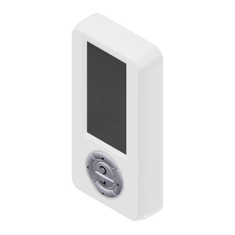
GATEXPERT GK-E Series User manual

INDUSTRIAL DOOR OPERATOR
WITH ELECTRONIC LIMIT SWITCH
USER MANUAL
(GK-E SERIES)
Website: www.gatexpertstore.com
E-mail: sales@gatexpertstore.com

Instructions for GK-E SERIES
www.gatexpertstore.com
WARRANTY
1. To repair against this warranty card and invoice during the warranty period.
2. Warranty period: 1 year after the date of invoice.
3. Without unauthorized dismantling, any product broken or damage due to quality
problem, we’ll offer the repair service for free or replace for free.
4. The malfunction and damages caused by incorrect use or man fault is not covered by
this warranty.
CONTACT US
E-mail: sales@gatexpertstore.com
Please fill in the order information in the form below.
All personal information you provided will be only used for warranty service and kept
strictly confidential.
Refer to this list when contacting GATEXPERT for technical service or assistance with
your automatic gate opener.
Order Number
Product Model
Purchase Date
Country / Region
Email Address
Issue Details

Instructions for GK-E SERIES
www.gatexpertstore.com
Safety Instruction
1. The industrial door operator should be installed and put into operation by qualified
personnel. Otherwise, serious personal injury or property damage may occur.
2. Installation and wiring must be in accordance with the construction standards and
electrical standards, diameter ≧1.5mm2; power must have a reliable grounding, ground
wire must be reliably connected to the place labeled ground tab, ground lead on the
power line is prohibited to be removed; front end of incoming power line should be
installed with electrical leakage protector which is in line with national standards.
3. This industrial door operator is only allowed to be installed on well-balanced door
which has balance spring, otherwise machine may be damaged due to overload.
4. Door should be flexible and run without stagnation; The end of door lead rail must be
installed with mechanical stop block and buffering booster to prevent the door from rolling
out.
5. Control unit should be installed on the wall or a post of 1.4 meters away from the
ground where the operation of door can be observed to prevent children from
inadvertently touching. Keep the remote control well, do not allow children to touch or
play in case of any danger. Do not use the remote control when you didn’t see the
operation of door.
6. Before repairing and moving the industrial door operator and its control unit, please cut
off the power supply, and make sure that the door has been locked and there is no any
risk of falling due to self-weight is null.
7. Pedestrian and vehicle are prohibited to go through or stay when the door is running.
8. Hand-pulled chain is prohibited to be pulled during the operation of the industrial door
operator to prevent the motor from damaged.
9. To ensure the safety of pedestrian and vehicle, it’s recommended to install the infrared
protection and airbag protection devices.
10. Please check the safety protection devices and the door running condition from time
to time to ensure the safety and stability of door operation.
Thank you for choosing this product!
Appreciate for your trust and support!
Please read this manual carefully before installation!
Please keep this manual properly even after installation!

Instructions for GK-E SERIES
www.gatexpertstore.com
CONTENTS
1.TECHNICAL PARAMETER TABLE……….…………………………………….………...…3
2.DIMENSION AND COMPONENT OF INDUSTRIAL DOOROPERATOR…............……4
3.INSTALLATION GUIDE OF INDUSTRIAL DOOR OPERATOR…………………….....…6
4.INDUSTRIAL DOOR OPERATOR WIRING…………………………………………..…...10
5.OPERATION INTERFACE ILLUSTRATION…………………………………….….....…..13
6.OPEN AND CLOSED LIMIT SWITCH SETTING…..……………………….……...….....14
7.WORKING MODE SETTING……………………………............…….…….…..…….......17
8.DIP SWITCH SETTING…………………………….............…….…….…..……..............17
9.PARAMETERS SETTING.........................…………..……………….....….…......….…..18
10.EXTERNAL ACCESSORIES WIRING……………..………………………...…………..20
11.REMOTE CONTROL PASSWARD SETTING…………..………………………......…..22
12.USE OF HAND-PULLED CHAIN ...............................................................................23
13.COMMON FAULTS AND COUNTERMEASURES .....................................................24
14.PACKING LIST…………………………………………………...……………...........……25

Instructions for GK-E SERIES
www.gatexpertstore.com
3
Technical Parameter Table of Door Operator
Model (Single Phase AC220V±10%)
GK30E
GK40E
GK100E
Rated Power
230W
300W
550W
Torque
30N.m
40N.m
100N.m
No-load Continuous Running Time
15 min.
8 min.
Max. gate area
15m2
20m2
35m2
Model (Three Phase AC380V±10%)
GK60SE
GK100SE
Rated Power
400W
550W
Torque
60N.m
100N.m
Max. gate area
30m2
40m2
No-load Continuous Running Time
15 min.
Other Parameters:
Thermal Protection Temperature
120℃
Reduction Ratio
1:58
No-load Rotation Speed
24r/min
Lubricating System
Oil-immersed
Noise
≤55dB
Hand Release Device
Manual release switch
Maximum Travel Limit
Output shaft rotates 20 rounds
Output Shaft Diameter
Φ25.4mm
Environment Temperature
-20℃~+50℃
Working Duty
S2-15min
Protection Class
IP54
Operator Dimension(mm)
357x135x218
Operator Weight(kg)
12.5

Instructions for GK-E SERIES
www.gatexpertstore.com
4
Technical Parameter Table of Control Unit
Model
GKB220E
GKB380E
Power Supply
AC220V/50Hz
AC380V/50Hz
Remote Control
Available
Available
Applicable Model
GK30E/40E/100E
GK60SE/100SE
External Three Button Switch Terminal
Available (Optional)
Available (Optional)
External Single Button Switch Terminal
Available (Optional)
Available (Optional)
Partial Opening Button Switch Terminal
Available (Optional)
Available (Optional)
Interlock Terminal
Available (Optional)
Available (Optional)
Infrared Photocell Terminal
Available (Optional)
Available (Optional)
Airbag Terminal
Available (Optional)
Available (Optional)
Loop Detector Terminal
Available (Optional)
Available (Optional)
Small-door Terminal
Available (Optional)
Available (Optional)
Multi-function Output Terminal
Available (Optional)
Available (Optional)
DC24V Power Terminal
Available (Optional)
Available (Optional)
Protection Class
IP54
IP54
Dimension and Component of Industrial Door Operator
Dimension

Instructions for GK-E SERIES
www.gatexpertstore.com
5
1Electronic limit switch part
②Gearbox
③Wiring terminals
④Plastic cover
⑤Door operator
⑥Hand-pulled chain
⑦Release handle
Component
Control Unit Dimension

Instructions for GK-E SERIES
www.gatexpertstore.com
6
1
2
3
4
5
6
7
1
2
3
4
5
6
7
Installation Guide of Industrial Door Operator
This product is commonly used for the industrial sectional door which was equipped
with balance spring and lifting industrial door. There are two installation ways for this
product: shaft drive installation and chain drive installation. The factory standard
configuration is for shaft drive installation. If users require chain drive type, they can
choose the appropriate sprocket chain accessories for installation needs.
Shaft Drive Installation Chain Drive Installation
Shaft Drive Installation
Chain Drive Installation
①Expansion Screw
①Driven Wheel
②Mounting Bracket
②Door Shaft
③Mounting Screw
③Chain
④Door Operator
④Mounting Bracket
⑤Special Flat Key
⑤Driving Sprocket
⑥Door Shaft
⑥Driving Sprocket Shaft
⑦Fixing Sleeve
⑦Door Operator

Instructions for GK-E SERIES
www.gatexpertstore.com
7
Step 1. Check the door
After the door is installed, adjust the torsion spring, ensure manually opening or
closing the door is flexible without stagnation, observe the rotation direction of the
rope sheave which should be consistent with the opening and closing direction of the
industrial door operator.
Step 2. Determine the installation position
Consider the boundary dimension and installation direction of the door operator,
determine the position of the mounting bracket, mark the insert cavity position, drill the
screw hole and fix the mounting bracket. (The mounting bracket can be fixed inside or
outside the door operator, recommended to be installed inside for the convenience of
disassembly of the door operator).

Instructions for GK-E SERIES
www.gatexpertstore.com
8
Step 3. Trial installing the door operator
Install a fixing sleeve on door shaft first, and insert the industrial door operator into the
door shaft.
Step 4. Pre-fix the industrial door operator
Fix the industrial door operator on mounting bracket with 4pcs hexagon head flange
bolts M10×20, do not tighten at this step.

Instructions for GK-E SERIES
www.gatexpertstore.com
9
Step 5. Find the direction of key slot
First pull the red handle A to the bottom to make the hand-pulled chain mechanism e
ngage with the main engine (Manual control mode).
Rotate the output shaft of industrial door operator by pulling the hand-pulled chain up
and down until the key slot of the output shaft is fully aligned with the key slot of the
door shaft.
Step 6. Mount the flat key and fixing sleeve
Mount the flat key, keep two fixing sleeves close to the two ends of the output shaft,
fasten the two M6 head screws in the key slot of door shaft in order to prevent the flat
key from loosening and falling off.
Step 7. Tighten the screws, prepare wiring and debugging Tighten all screws.
Finally pull green handle B to the bottom to make the hand-pulled chain mechanism
detach from the main machine (Electric control mode).

Instructions for GK-E SERIES
www.gatexpertstore.com
10
Industrial Door Operator Wiring
Wiring Between Door Operator and Control Unit
1. Motor Wire 2. Encoder Wire 3. Power Supply Wire

Instructions for GK-E SERIES
www.gatexpertstore.com
11
green
red
yellow
white
Wiring of Single Phase Operator
1——Motor Wire: U(blue) V(brown) W(black)
2——Encoder Wire: GND(white) A(yellow) B(red) VCC(green)
3——AC220V(single phase) Power Supply Wire
Note: Please make sure the wirings are tight and in good connection. After wiring,
remember to tighten up the IP plug to ensure all wirings completely fixed.
Warning: Please ensure the power supply wire is not plugged before you finish
all wirings.

Instructions for GK-E SERIES
www.gatexpertstore.com
12
green
red
yellow
white
Wiring of Three Phases Operator
1——Motor Wire: U(blue) V(brown) W(black)
2——Encoder Wire: GND(white) A(yellow) B(red) VCC(green)
3——AC380V(three phases) Power Supply Wire
Note:
1. Please make sure the wirings are tight and in good connection. After wiring,
remember to tighten up the IP plug to ensure all wirings completely fixed.
2. Please notice the phase sequence change when reconnecting wires. If the
phase sequence changed, the motor will run in opposite. The digital screen
won’t display abnormal if the phase sequence is correct.
Warning: Please ensure the power supply wire is not plugged before you finish
all wirings.

Instructions for GK-E SERIES
www.gatexpertstore.com
13
OPEN
CLOSE
STOP
OPEN
CLOSE
STOP
Operation Interface Illustration
STOP
DOWN
DIGITAL
SCREEN
UP
INDICATOR
LIGHT
REDUCE
INCREASE
CONFIRM
NEXT
Opening status
display
Working mode
display
Input status
display

Instructions for GK-E SERIES
www.gatexpertstore.com
14
Open and Closed Limit Switch Setting
OPEN
CLOSE
STOP
After powering on, the
digital will display
E-03 (hasn’t set the
limit switch)
OPEN
CLOSE
STOP
Press and hold
“NEXT” for 3
seconds, the digital
will display 00000
OPEN
CLOSE
STOP
OPEN
CLOSE
STOP
Enter password 21000:
press “+” twice; press
“NEXT” once; press “+”
once; press “CONFIRM”
once; The digital will
display P1

Instructions for GK-E SERIES
www.gatexpertstore.com
15
OPEN
CLOSE
STOP
OPEN
CLOSE
STOP
OPEN
CLOSE
STOP
OPEN
CLOSE
STOP
Press “confirm” once; The
digital will display P1-F1;
press “confirm” once again;
The digital will display — —
Shortly press “OPEN” to check
opening direction, if it’s correct,
then press and hold “OPEN” to set
the open limit switch position,
digital will flash — —
If the opening direction
is wrong, press and hold
“STOP” until the digital
displays“F”or “r”to
change the running
direction. After direction
changed, press and hold
“OPEN” to set the open
limit switch position.

Instructions for GK-E SERIES
www.gatexpertstore.com
16
CLOSE
STOP
OPEN
CLOSE
STOP
OPEN
CLOSE
STOP
OPEN
CLOSE
STOP
OPEN
Release the “OPEN” when
motor arrives at the open
limit switch position, press
“CONFIRM”, the digital will
display the encoder value
for 1 second and then show
— —, then you can set the
closed limit switch position.
Press and hold “CLOSE” to
set the closed limit switch
position until the gate runs to
proper closed limit position,
then release the button, press
“CONFIRM”, the digital will
display the encoder value for
1 second, then show P1-F2,
limit switch was set.
Press “NEXT” twice to
return to primary menu,
you can operate the
operator now.

Instructions for GK-E SERIES
www.gatexpertstore.com
17
CLOSE
STOP
OPEN
O N
1 2 3 4 5
Working Mode Setting
After these 2 steps, please check if the door running condition is to your
standard, if it’s good, you don’t have to do any other settings, the door will work
properly. If it’s not good, you should adjust the relative parameters.
Note:
1) Please adjust the door operator with the buttons on the control unit.
2) After adjustment, please make some trial running first, make sure
everything is correct, fit the control unit on a post that can be observed by you
and should be 1.4 high from the ground to keep it away from Children.
DIP Switch Setting:
ON(Up Position); OFF(Down Position)
No.1: ON-Mechanical Limit Switch; OFF-Electronic Limit switch
No.2: No function
No.3: No function
No.4: ON-Remote Control in Single Button Mode;
OFF-Remote Control in Three Buttons Mode;
No.5: ON-Enable Phase Sequence Detection;
OFF-Disable Phase Sequence Detection
Press and hold “-” for 4 seconds, you can
select manual control or automatic control
mode.
1. Automatic(A): Press “OPEN”, the door
will run to the open limit switch position,
after waiting for the programmed
auto-close time, it’ll automatically close to
the closed limit switch position.
2. Manual(H): Press “OPEN”, the door will
run to the open limit switch position, press
“CLOSE” the door will run to the closed
limit switch position.

Instructions for GK-E SERIES
www.gatexpertstore.com
18
Input Status:
Parameters Setting
Input Status
No.
Instruction
1
Stop
2
Open
3
Close
4
Photo Sensor
5
Air Bag
6
Loop Detector
7
Partial Opening
8
Single Cycle
9
Interlock
No.
Parameters
Value Range
Default
P1
P1-F1
Electronic limit switch setting
P1-F2
Pre-stop before arriving at the open
limit switch position
0-200
50
P1-F3
Pre-stop before arriving at the
closed limit switch position
0-200
60
P1-F4
Delay time for Auto-close
0-120 sec.
10
P1-F5
Height of partial opening
0-100%
50
P1-F6
Inch move for opening
0=Continuously
move;1=Inch move
0
P1-F7
Inch move for closing
0=Continuously
move;1=Inch move
0
P1-F8
Restore to factory setting of P1
0=No;1=Yes
0
P2
P2-F1
Stop of external three buttons
switch
0=NO;1=NC
0
P2-F2
Partial opening
0=NO;1=NC
0
P2-F3
Single cycle
0=NO;1=NC
0
P2-F4
Photo sensor
0=NO;1=NC
0
P2-F5
Loop detector
0=NO;1=NC
0
P2-F6
Airbag
0=NO;1=NC;2=pulse
0
P2-F7
Mechanical limit switch
0=NO;1=NC
1
This manual suits for next models
3
Table of contents
Popular Door Opening System manuals by other brands
DoorHan
DoorHan ARM 320 Installation and operating manual
REYNAERS
REYNAERS 062.8251 Technical manual

Kason
Kason 8600EZ installation instructions
Kenwa
Kenwa NHN 1600U-M Series Installation instruction
Autoslide
Autoslide AutoSwing ASW8-1 installation manual

Dormakaba
Dormakaba ORACODE 480 Series installation instructions
RollSeal
RollSeal RS-600 Series manual
eku
eku COMBINO 60 H Vorfront Mounting instructions
SDC
SDC 1511S installation instructions
B&D
B&D Controll-A-Door Smart SDO-7 installation instructions
Norton
Norton CloserPlus CLP7570 Series installation instructions
Dormakaba
Dormakaba 7400 FH installation instructions
