RollSeal RS-600 Series User manual

4801-5181D 1
RS-600 High-Temperature
Oven Door Manual

RS-600 High-Temperature Oven Door Manual2
Section 1: Introduction...........................................................................................................................................
Section 1.1: Safety................................................................................................................................................................................
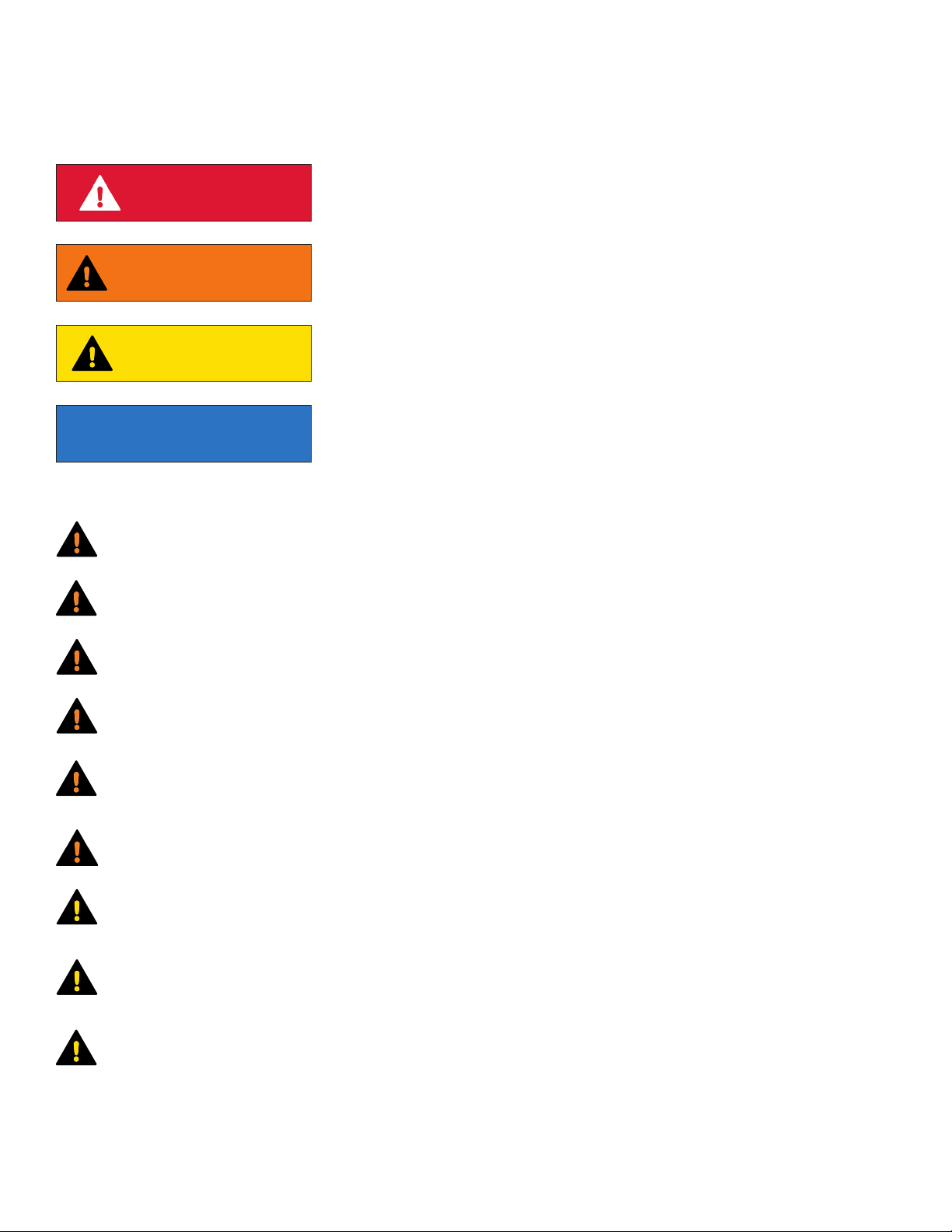
Section 1.1.1: Definitions of Signal Words and Symbols.......................................................................................................................
Section 1.1.2: Statements.......................................................................................................................................................................
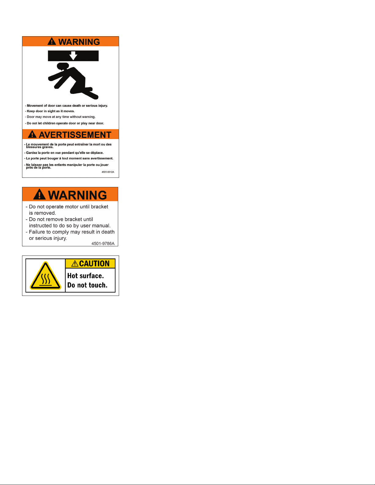
Section 1.1.3: Product Labels..................................................................................................................................................................
Section 1.2: Scope of Manual..............................................................................................................................................................
Section 1.3: Limited Warranty.............................................................................................................................................................
Section 1.4: Door Overview.................................................................................................................................................................
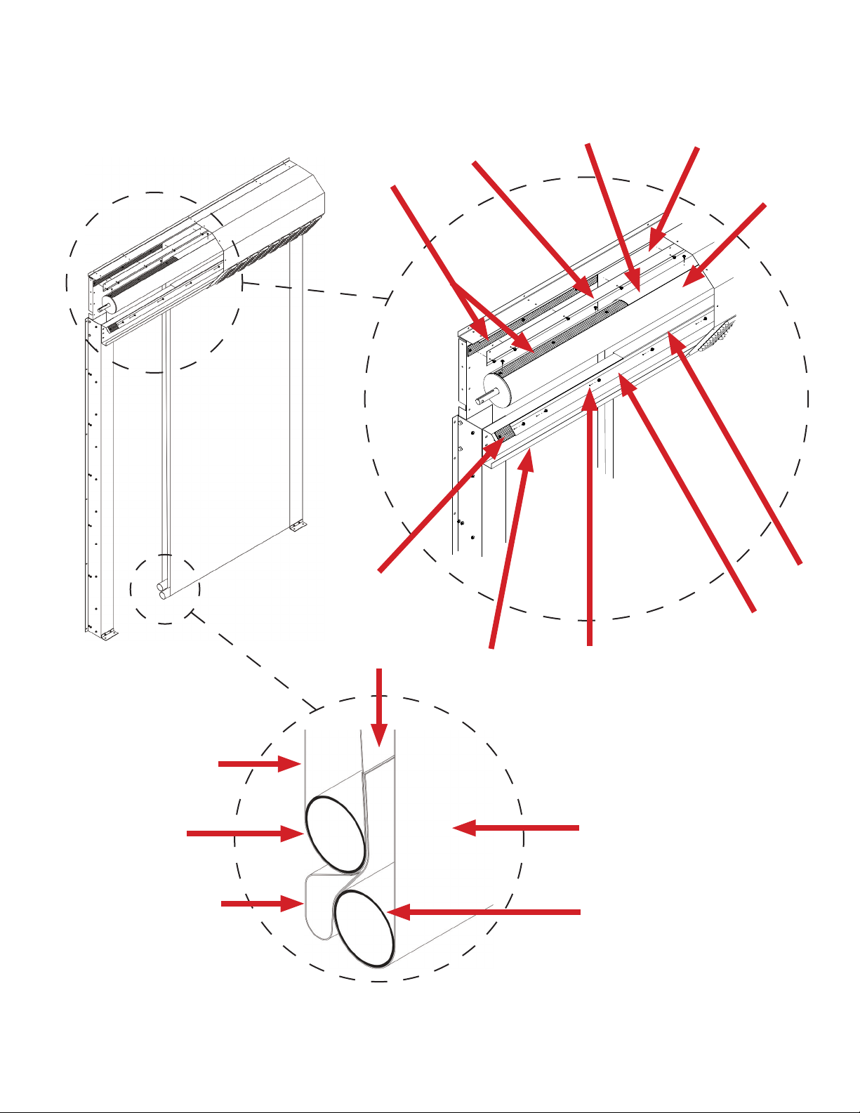
Section 1.5: Components.....................................................................................................................................................................
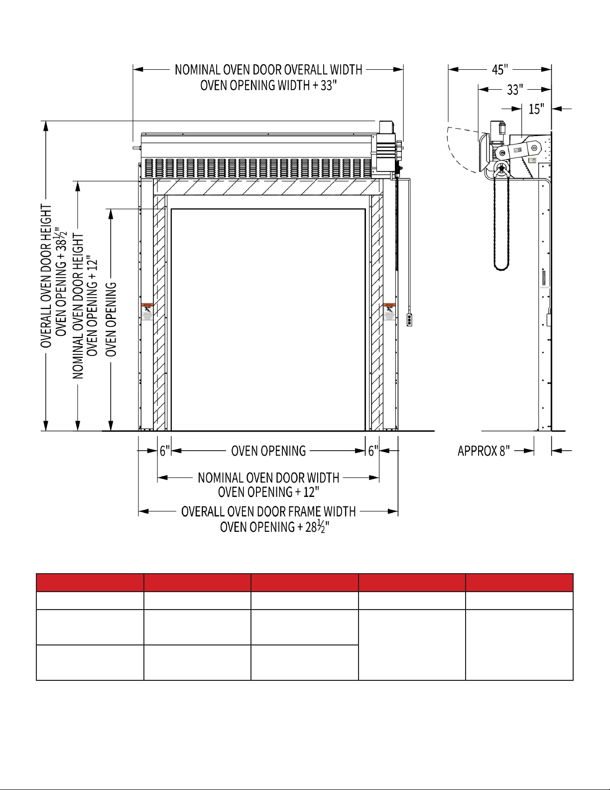
Section 1.6: Dimensions......................................................................................................................................................................
Section 1.7: Installation Requirements...............................................................................................................................................
Section 2: Installation.............................................................................................................................................
Section 2.1: Adjust Framing and/or Clear Opening............................................................................................................................
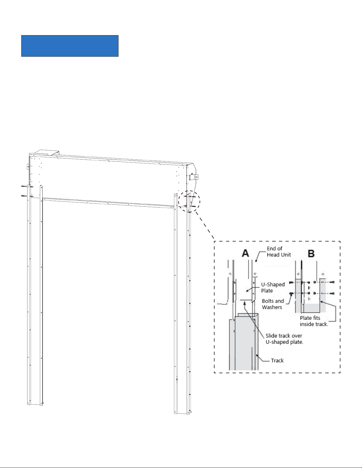
Section 2.2: Connect Tracks to Head Unit...........................................................................................................................................
Section 2.3: Raise Door to Clear Opening...........................................................................................................................................
Section 2.3.1: Up to 6' W x 9' H................................................................................................................................................................
Section 2.3.2: Between 6' W and 12' W...................................................................................................................................................
Section 2.3.3: Between 12' W and 16' W.................................................................................................................................................
Section 2.4: Mount Door to Clear Opening.........................................................................................................................................
Section 2.5: Install Inside Seal.............................................................................................................................................................
Section 2.6: Remove Safety Bracket From Motor Side.......................................................................................................................
Section 2.7: Install Motor.....................................................................................................................................................................
Section 2.8: Install Chain Drive Assembly...........................................................................................................................................
Section 2.9: Remove Safety Bracket From Other Side.......................................................................................................................
Section 2.10: Adjust Limit Switches....................................................................................................................................................
Section 2.11: Wire Motor......................................................................................................................................................................
Section 2.12: Install Infrared Safety Beam System.............................................................................................................................
Section 2.13: Wire Safety Beam Emitter and Receiver........................................................................................................................
Section 2.14: Install Switch..................................................................................................................................................................
Section 2.15: Enable Maintained Activation.......................................................................................................................................
Section 2.16: Prepare for Operation....................................................................................................................................................
Section 3: Operation...............................................................................................................................................
Section 3.1: Switch...............................................................................................................................................................................
Section 3.2: Remote Transmitter.........................................................................................................................................................
Section 4: Maintenance...........................................................................................................................................
Section 4.1: Inspecting and Tightening Chain....................................................................................................................................
Section 4.2: Replacing Panels..............................................................................................................................................................
Section 4.3: Replacing Floating Seal...................................................................................................................................................
Table of Contents
3
3
3
3
4
5
5
6
7
8
8
9
9
10
11
11
12
14
16
17
18
19
20
22
23
24
25
26
27
28
29
30
30
31
32
32
32
33

4801-5181D 3
Section 1.1: Safety
Section 1: Introduction
DANGER This indicates a hazard that, if not avoided, will result in death or serious injury.
WARNING This indicates a hazard that, if not avoided, could result in death or serious injury.
CAUTION This indicates a hazard that, if not avoided, could result in minor or moderate injury.
NOTICE This indicates important information that is not related to hazards.
All wiring must be in accordance with national electrical codes as well as any applicable local codes.
The drive is intended for incorporation into electrical control systems or machines. The installer must ensure the drive
is installed safely and in accordance with any regulations which apply to the end product at the place of use (e.g. safety
or electromagnetic compatibility). To ensure mechanical safety, additional safety devices such as electromechanical
interlocks may be required.
Disconnect all power sources before installing or performing maintenance on this equipment.
Impact with the moving door may result in death or serious injury.
The door assembly contains dangerous rotating machinery. Keep hands, clothing, etc. clear during operation. Do not
operate the door unless all guards and covers are in place.
The installer is responsible for complying with all relevant regulations (e.g. wiring and accident prevention). Particular
attention must be paid to the cross-sectional areas of conductors, the selection of fuses and other electrical protection,
and the use of protective ground/earth connections.
California Proposition 65 Warning: This product can expose you to chemicals, including lead, which is known to the State
of California to cause cancer or birth defects or other reproductive harm. For more information, go to
www.p65warnings.ca.gov/furniture.
Only qualified personnel familiar with the construction and operation of this equipment and the hazards involved are to
install, adjust, and/or service this equipment.
Section 1.1.2: Statements
The voltages in the power cables and certain parts of the drive may result in death or serious injury. If the drive has been
used, it must be isolated for five minutes before any work commences.
Section 1.1.1: Definitions of Signal Words and Symbols

RS-600 High-Temperature Oven Door Manual4
Label 4501-6322 indicates the tracks and the panel can become hot during operation.
Two copies are applied to the tracks (one le and one right).
Section 1.1.3: Product Labels
Label 4501-9786 indicates the motor must not be operated until the safety brackets have
been removed when prompted to do so by this manual. Two copies are applied to hang
tags, one of which is attached to each safety bracket.
Label 4501-6312 indicates the moving door can cause death or serious injury. Two copies
are applied to the door. One is located inside the door opening; the other is located
outside the door opening.

4801-5181D 5
Section 1.2: Scope of Manual
This manual describes the following aspects of the RollSeal RS-600 high-temperature oven door:
1. Installation of the door and its components.
2. Operation of the door, including activation methods.
3. Maintenance, including adjustment and replacement of various components.
NOTICE This document is subject to change without notice. The latest version is maintained at
rollseal.net/rollseal-technicals/.
Section 1.3: Limited Warranty
RollSeal, a division of HH Technologies, Inc., warrants the RollSeal Door ("the Product") to be free from defects in material and/or
workmanship for a period of either (a) one year from the date of invoice or (b) 40,000 cycles, whichever comes first, provided the
Product is installed and used in strict accordance with oicial documentation. Liability is limited to the sale price of the Product
or, at RollSeal's discretion, to the replacement of the Product upon its return.
This Limited Warranty excludes any labor, equipment, transportation, and/or service expenses that may be required to remedy the
warranted defect(s); all such charges must be funded by the purchaser. Neither the Product nor any of its component parts are to
be returned for repair or replacement until they have been inspected and/or a Return Goods Authorization (RGA) number has been
issued.
Complaints are to be directed first to the authorized distributor who sold the Product. If satisfaction is not obtained and/or the
distributor cannot be contacted, contact the Warrantor listed below, directed to the attention of "Customer Service Manager".
This Limited Warranty is void if (a) the Product and/or any of its component parts are found to have been misused, abused, or
otherwise tampered with by unqualified personnel; (b) any of the Product's component parts have been replaced by anything
other than authorized RollSeal replacement parts; (c) the Product has been modified in any way other than oicially sanctioned
upgrades made by qualified personnel using authorized RollSeal accessories; (d) the Product has not been appropriately
registered by its original purchaser; and/or (e) the customer cannot provide proof of purchase indicating them to be the Product's
original owner.
This Limited Warranty is made solely to the original purchaser of the Product. It cannot be transferred.
This Limited Warranty is in lieu of any and all other representations and/or warranties, expressed or implied, including any implied
warranty of merchantability and/or fitness for a particular purpose. The remedy set forth by this Limited Warranty shall be the
exclusive remedy available to any entity. No entity has the authority to bind RollSeal to any representation or warranty other
than this Limited Warranty. RollSeal shall not be liable for any damages or losses resulting from any application of the Product or
caused by any defect, failure, or malfunction of the Product.
This Limited Warranty gives you specific legal rights. You may have additional rights, as some areas do not allow the exclusion or
limitation of incidental or consequential damages. The above limitation or exclusion may therefore not apply to you.
Warrantor: HH Technologies (d.b.a. RollSeal)
Address: 1733 County Road 68; Bremen, AL 35033
Phone: 256-287-7000
Email: customerservic[email protected]

RS-600 High-Temperature Oven Door Manual6
Specifications
Type D6 (RS-600) Manual Override Chain Hoist
Application High-Temperature Oven Horsepower 1/2 HP
Dierential Pressure -0.05 to -0.15 inH2OFlame Resistance FTNS 191A/M5903.1
Seal Type Industrial Hook-and-Loop Drive Attachment Chain
Drive Type Gearhead Jacksha Infrared Safety Beam Standard (Monitored)
Standard Drive Mounting Oven Hood; Right of Head Unit Brake Mechanical
Speed 6” per Second Frame Material G90 Galvanized
Input Voltage 1PH: 115V, 208V, 230V Tension Pipe Material Impact-Resistant G90 Galvanized
3 PH: 230V, 460V
Input Current 1PH: 8.6A, 4.1A Panel Material Aluminized Fiberglass
3PH: 2.2A, 1.1A
Motor Frequency 50 Hz or 60 Hz Standard Switch 3-Position (Open/Close/Stop)
Phase 1PH or 3 PH
Section 1.4: Door Overview
Operational Parameters
Operational Temperature Range:
200°F to 500°F (93.3°C to 260°C)
500°F (260°C) is the maximum operational temperature. Exceeding this temperature will
shorten material life and void warranties.
Dierential Pressure:
-0.05 inH2O to -0.15 inH2O
The oven must be balanced to create negative dierential pressure from the exterior
environment. The pressure must be maintained between -0.05 inH2O and -0.15 inH2O.
Burner airflow must be routed
away from the door.
Air from burner systems must be directed away from the door to reduce exterior
temperatures, maintain low seal temperature, and extend door life. The aluminized
coating radiates heat away from the door, but direct burner airflow will result in higher
door temperatures.
Limitations
The door is designed to be used up to 8 hours per day on an oven operating between
400°F (204.4°C) and 500°F (260°C). If your application operates within this temperature
range for a longer period of time, contact RollSeal for further information.

4801-5181D 7
Section 1.5: Components
Inside Tension Pipe
Sealing Flap
Back Panel
Center Panel
Front Panel
Outside Tension Pipe
Loop
Top Bar #8 x 1/2" Pan-Head
Screw (Typical)
Front Panel
Retention Plate
Front Panel
Loops
Back Panel
Retention Plate
Center Panel Back Panel
Drive Sha

RS-600 High-Temperature Oven Door Manual8
Section 1.6: Dimensions
Section 1.7: Installation Requirements
Door Size Personnel Equipment Tools Time
Up to 6’ W x 9’ H 2 - Ladder - Standard Hand Tools ~ 3 Hours
Up to 12’ W x 12’ H 3
- Ladder
- Forkli
- Scissor Li - Standard Hand Tools
- Reciprocating Saw ~ 5 Hours
Up to 16' W x 16' H 4
- Ladder
- Forkli
- 2 Scissor Lis

4801-5181D 9
Section 2: Installation
Section 2.1: Adjust Framing and/or Clear Opening
1. Determine the required width and height of the clear opening. If necessary, adjust the dimensions of the mounting posts
and/or framing members to suit the nominal dimensions of the door.
2. Ensure the mounting posts and/or framing members are positioned so the screw holes in the outer flanges of the vertical
tracks will align with them.
3. Allow at least 12" (ideally 18") of clearance above the head unit.
4. Allow at least 6" of clearance on the outside of each track.
5. Ensure the top screw holes in the head unit will overlap and fit flush with the framing.
6. Ensure the screw holes in the vertical tracks align with the framing. The predrilled screw holes in the inner and outer flanges
will serve as attachment points when the assembly is mounted.
Read this manual in its entirety before beginning the procedure. Inspect the contents of the shipping crate for damaged, loose, or
missing components. If any components are damaged, loose, or missing, contact your RollSeal distributor immediately.

RS-600 High-Temperature Oven Door Manual10
Section 2.2: Connect Tracks to Head Unit
Each end of the head unit has a U-shaped plate that fits the corresponding track. The plate has four bolt holes (two on the outside
and two on the inside) that match the bolt holes in the tracks.
1. Arrange the head unit and both tracks on the floor, face-down in front of the clear opening.
2. Align each track with the plate at the corresponding end of the head unit.
3. Slide each track onto the outside of the plate.
4. Insert the bolts through the bolt holes, then install the nuts.
NOTICE If you are installing a door up to 6' W x 9 H', perform the following steps now. Otherwise,
skip to the appropriate section (Section 2.3.2 if between 6' W and 12' W; Section 2.3.3 if
between 12' W and 16' W) until instructed to return to this section.

4801-5181D 11
Section 2.3: Raise Door to Clear Opening
Installing an oven door up to 6' W x 9' H requires at least two personnel.
1. Ensure the overall height and width of the clear opening meet the requirements.
2. Ensure the door opening and frame are square and level.
3. Center the door assembly with the clear opening. Align the bottom of each track with the corresponding framing boards and
posts of the clear opening.
4. Position at least one person on each side of the door assembly.
Section 2.3.1: Up to 6' W x 9' H
NOTICE Ensure the tracks are aligned so their inner and outer flanges will overlap the support
framing or posts when the door assembly is raised into position.
5. Slowly raise the top of the door assembly toward the wall.
6. Lean the door assembly upright against the oven frame.
7. Ensure the gasket material secured to the backs of the track flanges is flat.
8. Mount the door to the clear opening according to Section 2.4.

RS-600 High-Temperature Oven Door Manual12
Section 2.3.2: Between 6' W and 12' W
Installing an oven door assembly between 6' W and 12' W requires at least three personnel, a forkli, and a scissor li.
1. Center the pallet and the head unit in front of the clear opening, leaving enough space for the forkli to operate between the
clear opening and the head unit.
2. With the forkli positioned between the head unit and the clear opening, use it to raise the pallet approximately 3' from the
floor.
3. Slide the head unit from the pallet to the forks, then remove the pallet from the installation area.
4. With the head unit raised o the floor, connect the tracks to the head unit according to Section 2.2.
5. Position the scissor li in front of the door assembly, ensuring the platform is aligned with the assembly.
6. Use the forkli to raise the door assembly until it is flush with the scissor li's guardrails.
7. With one person operating the scissor li and one positioned at each track of the door assembly, slide the door assembly from
the forkli to the scissor li. Once this is done, remove the forkli from the installation area.
8. Use the scissor li to move the door assembly toward the clear opening.
9. Once the door assembly has been centered with the clear opening and all personnel are in position (on the scissor li and at
each track), begin tilting the door assembly until it is in a standing position.
10. Once the door assembly is in a standing position on the scissor li, use the li to raise the assembly 6" from the floor, then
move it into position against the clear opening.
WARNING Ensure the area is clear before lowering the door assembly.
11. Lower the door assembly until the tracks meet the floor, then push the assembly until it is flush against the clear opening.
12. Ensure the gasket material secured to the backs of the track flanges is flat.
13. Mount the door to the clear opening according to Section 2.4.

4801-5181D 13

RS-600 High-Temperature Oven Door Manual14
Section 2.3.3: Between 12' W and 16' W
Installing an oven door assembly between 12' W and 16' W requires at least four personnel, a forkli, two scissor lis, and a
reciprocating saw.
1. Center the pallet and the head unit in front of the clear opening, leaving enough space for the forkli to operate between the
clear opening and the head unit.
2. With the forkli positioned between the head unit and the clear opening, use it to raise the pallet approximately 3' from the
floor.
3. Use a reciprocating saw to remove 4' from each side of the pallet, causing the ends of the head unit to hang over the edge.
4. Use the forkli to move the head unit toward the clear opening.
5. Connect the tracks to the head unit according to Section 2.2.
6. Use the forkli to raise the door assembly until it is above the scissor lis' guardrails.
7. Position the scissor lis under the overlapping sides of the head unit.
8. Lower the head unit onto the scissor lis.
9. With one person operating each scissor li and one positioned beside each track, slide the door assembly from the forkli to
the scissor lis. Once this is done, move the forkli away from the installation area.
10. Use the scissor lis to move the door assembly toward the clear opening.
11. Once the door assembly has been centered with the clear opening and all personnel are in position (on the scissor lis and at
each track), begin tilting the door assembly until it is in a standing position.
12. Once the door assembly is in a standing position on the scissor lis, use the lis to raise the assembly 6" from the floor, then
move it into position against the clear opening.
WARNING Ensure the area is clear before lowering the door assembly.
13. Lower the door assembly until the tracks meet the floor, then push the assembly until it is flush against the clear opening.
14. Ensure the gasket material secured to the backs of the track flanges is flat.
15. Fasten the door to the clear opening according to Section 2.4.

4801-5181D 15

RS-600 High-Temperature Oven Door Manual16
Section 2.4: Mount Door to Clear Opening
1. Fasten a self-tapping screw through the center hole in the top flange.
2. Level the head unit.
3. Fasten self-tapping screws through the remaining holes in the top and bottom flanges on the head unit.
4. Level the tracks and square them with the head unit, then fasten self-tapping screws through the flanges on the tracks.
5. Drill two 1/4" holes in the floor through the flange at the bottom of each track.
6. Install four hammer-set anchors through the holes you drilled in Step 5.
First Screw

4801-5181D 17
Section 2.5: Install Inside Seal
The inside seal must be secured to the front wall of the oven. The door is oversized 6" on each side to accommodate this.
1. Pull the pre-installed sealing flap out of the track and stretch it over the rear track flange.
2. Position one of the metal strips along the edge of the sealing flap.
3. Secure the strip 1/2" from the edge of the flap using pan-head screws.
4. Secure all metal strips to the front panel of the oven, ensuring the sealing flap is tight.
Gasket Material
3" W Poly Loop
Sealing Flap
(Behind Floating Seal)
Metal Strip
Oven Panel
4" W
Poly Loop

RS-600 High-Temperature Oven Door Manual18
Section 2.6: Remove Safety Bracket From Motor Side
1. Remove the tag from the safety bracket on the same side as the motor.
2. Remove the nut and bolt locking the drive sha to the bracket.
3. Remove the two bolts holding the bracket to the head unit.
WARNING The safety brackets on the le and right sides of the head unit are designed to lock
the drive sha in place during shipping and installation, preventing the curtain from
dropping. Do not remove the other safety bracket until instructed to do so in Section 2.9.
Do not attempt to operate the door while either safety bracket is installed.

4801-5181D 19
Section 2.7: Install Motor
1. Remove the hardware kit from the mounting bracket.
2. Align the motor with the tops of the vertical slots on the front of the mounting bracket, then run the four 3/8" x 1-1/2" bolts
from the hardware kit through the motor base and the bracket.
3. Place the washers and lock nuts from the hardware kit on the inside of the bracket, then tighten the nuts until they are fully
seated.

RS-600 High-Temperature Oven Door Manual20
Section 2.8: Install Chain Drive Assembly
1. Connect the two halves of the spreader bar to each other using the provided 3/8" x 1" hex-head bolts, washers, and lock nuts.
2. Place the spreader bar and the sprockets over the shas.
3. Place the chain around the sprockets.
Other manuals for RS-600 Series
1
Table of contents
Other RollSeal Door Opening System manuals
Popular Door Opening System manuals by other brands

Assa Abloy
Assa Abloy Lockwood 5831 Series manual

GAL
GAL MOVFR installation manual

Mhouse
Mhouse GD0 Installation instructions and warnings

Detex
Detex AO19-1 manual

GFA
GFA ELEKTROMAT KE 80.12-55,00 Ex installation instructions

Automatic Technology
Automatic Technology DOMINATOR EasyRoller instruction manual

SUGATSUNE
SUGATSUNE Lamp FD30-F installation manual

MOTION4
MOTION4 EvoDrive+ installation manual

Merlin
Merlin Overdrive Installation and operating instruction manual

ALL WEATHER
ALL WEATHER 8000 Series installation instructions

Dormakaba
Dormakaba ED100 operating & maintenance manual

Dorma
Dorma 96 GSR-EMF Mounting instructions