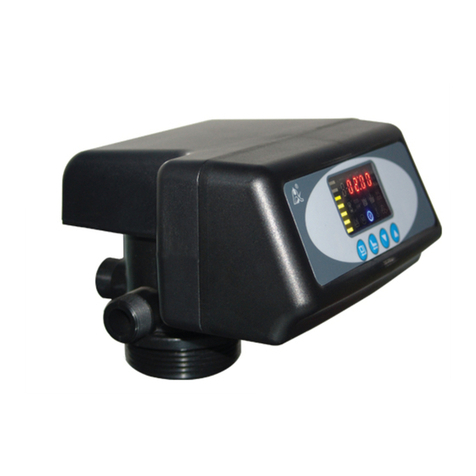
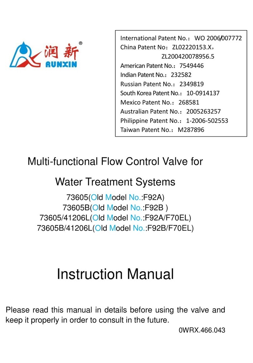
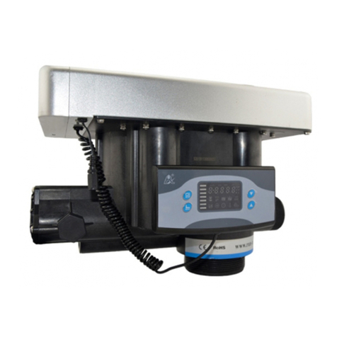
Runxin 63504 User manual

ti)
/e~
ir®
~
RUNXIN
lntemational Patent Public No.:
wo
2006/007772
China Patent No.: ZL02220153.X,
ZL200420078956.5
US
PatentNo.: 7549446
India Patent No.: 232582
Russia Patent
No
.:23498
19
Soulh Korea Patent
No
.:10-0914137
Mexico Patent No.: 268581
Australia Patent No.: 2005263257
Philippine Patent No.: 1-2006-502553
Taiwan Patent No.:M287896
Multi-functional
Flow
Control
Valve
forWater
Treatment
Systems
63504, 63504B (OldModelNo.:
F63Cl,
F63Gl)
63604, 63604B (OldModelNo.: F63C3,F63G3)
73504, 73504B (OldModelNo.:
F68Cl,
F68Gl)
73604, 73604B (OldModelNo.: F68C3,F68G3)
Usermanual
Please
read
this
manual
in
detalls
beforeusingtbis
valve
andkeep
it
properly
in
order
to
con
s
ult
in
the
future
0WRX.466.S01

MODEL:63504-F63Cl/63604-F63C3/73504-F68Cl/73604-F68C3
Before the valve
put
into
use
, please fill
in
th
e
below
content so
as
to
help
us
to
refer
in
the future.
Tbe Program Type Setting (Operation byprofessional)
When
all
symbols lighton, press
and
hold
GJ
and
" buttons for 5 seconds
to
enter
the
menu
of
valve
model
selection. Please set the program type
in
accordancewiththe
product type. (Time
clock
type
by
day
s
or
hours
or
Meter type); for example,
F63Cl
or
F63Gl
should
be
set
to
F63Bl
;
F6
3C3
or
F63G3 shouldbe
set
to F63B3.You couldn't
set
to other type.)
Softener System Configuration
TankSize:
Dia
.
------~mm,
Height
mm
;
ResinVolume
--------~L;
BrineTankCapacity
___
L;
Hardness
ofRaw
Water
_______
.mmol/L;
Press
ure
oflnlet
Water
________
MPa
;
ControlValve Model.
__________
_ Number
__
_
The
Specification
of
Drain Line
Flow
Control
_________
_
InjectorNo.
__________
~
Water Source: Ground-wat
erO
FilteredGroond-water
□
Tap
Wat
er
□ Other
___
_
Parameter
Set
Parameter
Uni
t
Fa
ctory Default ActualValue
ControlModeA-01
(
02
,
03
,
04
) / A-01
Unit
Mode
Hu0l
(
02
, 03 ) / HUOl
WaterTreatmentCapacity (
Meter
type)
fi
l
10
ServiceDays (Tune
of
clocktype,
by
da
ys)
D.
03
ServiceHours (
Tme
clocktype,byhours) H. 20
Regen
eration
Tim
e /
02
:
00
Backw
as
h
Time
Min
.
10
:
00
Brine
&
Slow
RinseTime Min.
60:
00
Brine
Refill
Tim
e Min.
05
:
00
Fast Rinse
Tim
e
Min
.
10:
00
Interval R
eg
eneration
Day
s D.
30
Output
Mod
e b-01 (
02
) / b-01
e
1f
there is
no
special requirement
when
product purchase,
we
choose
5#-
drain
line
flow
control and
9#
injector
for
the standard configuration.
-1-

MODEL:63504-F63Cl/63604-F63C3/73504-F68Cl/73604-F68C3
Catalogue
Notice.................................................................................................................................3
1. ProductOverview..........................................................................................................
.4
1.1.
Main
Application& Applicability...............................................................................4
1.2. ProductCharacteristics................................................................................................4
1.3. Service Condition........................................................................................................6
1.4.Product Structure
and
Technical Parameters...............................................................7
1.5. Installation...................................................................................................................8
2. Basic Setting & Usage.........
..
.............................................
..
.
..
.............
..
......................
11
2.1.
The
Function
of
PC
Board...............................................................
..
.......................
.11
2.2. Basic Setting & Usage.......................................................................................
..
......12
3. Applications.
..
..........
..
..............................
..
..........................
..
......................................
.16
3.1. Softener
Flow
Chart
..
................................
..
..............................................................
16
3.2.
The
Function
and
Connection
of
PC
Board..................................................
..
..........
.18
A.
Signal OutputConnector.............................................................................................19
B.
Interlock.
..
...................
..
..........................
..
...............
..
.................................................
22
C. Pressure
Relief
Output................................................................................................
22
D. Remote Handling Connector..................
..
...................................................................
23
E. InterlockSystem..........................................................................................................23
F.
Series System..........................
..
.........
..
........................................................................
23
3.3. System Configuration
and
FlowRateCurve............................................................
24
3.4. Parame
ter
Settlement.................................................................................................
26
3.5. ParameterEnquiry
and
Setting.................................................................................
27
3.6. Trial Running................
..
..................................
..
........................................................32
3.7. Trouble-Shooting.......................................................................................................33
3.8. Assembly & Parts......................................................................................................
37
4. Warranty
Card
...............................................................................................................45
-2-
MODEL:63504-F63Cl/63604-F63C3/73504-F68Cl/73604-F68C3
Notice
eTo
ensure normal operation
ofth
e valve, pleaseconsult
with
profess
ional
installation
or
repairingpersonnel before use it.
elfthereare any
ofpipeline
engineering
and
electric
works,
there
mu
st
be
finished
by
professional at
the
time
of
installation.
•
Do
not
use
the control valve withthe
water
thatis unsafe
or
unknownquality.
• Depending
on
the changing
of
working environment
and
waterrequirement, eachpar-
ameter
of
softenershould
be
adjusted accordingly.
•
When
the watertreatmentcapacity is too
low
, please
check
the
resin.
If
the
reason
is
shortage
of
resin,please add;
if
the resin
is
turn
to
reddishbrown
or
broken, please replace.
eTestwaterperiodically
to
verify thatsystemis performing satisfactorily.
esodium used in
the
water
softeningprocess should
be
considered
as
part
y
our
overall
dietarys
alt
intake. Contactdoctor
if
you
are
on
a
low
sodium diet.
• Ensure thatthere is solid
salt
all the time
in
the
brinetank
in
thecourse
of
using,
when
this valve is
used
for
softening.
Toe
brine tankshould
be
added thecleanwatersoftening
salts
only
,
at
least99.5% pure, forbidding use the smallsalt.
•
Do
not
put
the valve near the
hot
resource,
high
humidity, corrosive, intense magnetic
field
or
intenselibrations environment.
And
do
not
leave
it
outside.
eForbidden
to
carrythe injectorbody.Avoid
to
use injector
body
as
support
to
carrythe
system.
• Forbidden
to
use
the brine tube
or
otherconnectors
as
support
to
carry
the
sy
s
tem
.
• Please
use
this product
under
the
water
temperaturebetween 5 -
50
't:, waterpressure
0.
15
~0.6MPa. Failure
to
use
this product under
such
conditions voids the warranty.
elfthe
waterpressure exceeds 0.6Mpa, a pressure reducing valve must
be
installedbefore
the
water inlet. While,
if
the
waterpressure under
O.
l 5MPa, a booster
pump
must
be
ins-
talledbefore
the
water
inlet.
• Itissuggested to install
PPR
pipe, corrugatedpipe
or
UPVCpipe, instead
ofITLSG
pipe.
eDo
notletchildrentouch
or
play, because carelessness operating
may
cause theprocedure
changed.
•
When
the attached cables
of
this
product
and
transformer
are
changed,
they
must
be
changed
to
the one that
is
from
our
factory.
- 3-

MODEL:63504-F63Cl/63604-F63C3/73504-F68Cl/73604-F68C3
1. Product Overview
1.1. MainApplication & Applicability
Used for softening
or
demineralizationwatertreatment systems
Be
suitable for
Residential softening system
Ion exchange equipment
Boilersoftening watersystem
RO pretreatment softening system, etc.
1.2. Product Characteristics
esimple
structure
and
reliable sealing
It
adopts hermeticheadfaces withhigh degree pottery and corrosionresistance for
opening andclosing.
It
combines with Service, Backwash, Brine & SlowRinse, Brine
Refill andFast Rinse.
e
No
waterpass the valve
in
regeneration
in
singletanktype.
eManual
function
Realize regenerationimmediately
by
pushing " " " atanytime.
e Long outage indicator
If
outage overrides 3days, " 12: 12" will flash to remind people to resetnewtime
of
day.
Toe othersetparameters do notneed to reset. Toe process will continue
to
work after
poweron.
•
LED
dynamic screen display
Toe stripe
on
dynamic screenflash, itindicates the control valve is
in
service, otherwise,
it
isin regeneration cycle.
• Buttonslock
No operations to buttons onthe controllerwithin 1 minute, buttonlock indicatorlight
onwhich representbuttons are locked. Before operationpress and hold the O
and
O
buttons for 5 seconds
to
unlock. This function can avoid incorrect operation.
• Interval backwashtimes (Suitable for F68)
It
couldsetup interval backwashtimes for F68 up-flow regeneration valve whichmeans
several times
of
services
but
onetime
of
backwash. Toe setting
of
interval backwash time
is depending onthe local water turbidity. (Toe lower the turbidityis , the longer
ofthe
intervalbackwashtime canbe set)
en
can
choose time clocktype
or
meter
type
by
program
selection
When all symbols lighton, press and hold
4'
and
gJ
buttons for 5 seconds
to
enter
the menu
of
valvemodel selection. Please set the programtype inaccordance withthe
producttype. (Time clock type
by
days
or
hours
or
metertype) (Notice: Toe meter type
producthas one flow meter and flow meter cable,
but
the time clock type doesn't have).
- 4-

MODEL:63504-F63Cl/63604-F63C3/73504-F68Cl/73604-F68C3
• Four
kinds
of
metertypecan be selected (Suite
for
F63C3, F68G3,F68C3 ,F68G3)
Model Name lnstruction
Regenerate onthe day although the available volume
of
A--01
MeterDelayed treated waterdrops to zero
(O).
Regeneration starts atthe
regenerationtime.
A--02
Meter Regenerate immediatelywhenthe available volume
of
Immediate treated waterdrops to zero(0).
Intelligent MeterDelayedRegeneration type, butby setting Resin
A--03
Volume, Feed WaterHardness, RegenerationFactor, the
MeterDelayed controllerwill calculate the System Capacity.
Intelligent Meter Immediately RegenerationType, but
by
setting
A-04 Meter Resin Volume, Feed Water Hardness, Regeneration
Immediate Factor, the controller will calculate the System Capacity
• There are two kinds
of
regeneration mode for time clocktype
Whenthe programis set to time clock typeby days
(Such
as
F63Cl, F68Cl, etc.)
it
can
bechanged to be by hours by dialing the
red
switchonmain control boardto " l " (Refer
to
Pl8
Figure). Pointingto
"ON"
mean the time clock type service
by
days.(Attention:
After dialing the switch, please restart the power)
• Interlockfunction
It
has a function
of
interlockto realize onlyonevalve in regeneration butthe othervalves
are
in
service while severa! valves parallel in system. Inmulti-steps treatmentsystems such
as
RO
pre-treatment, when
severa!
valves
are
inseries, there is only onevalve inregeneration
or
washing to ensure pass water all the times while different valves
in
regeneration
or
washing.(Applicationrefer to Figure 3-9)
esignaloutput
There is a signal output connector on main control board.
lt
is for controlling extemal
wiring (Refer to Figure from Figure3-l to Figure 3-8).
There are twokinds
of
outputmode
s:
b-01 Mode: Tumon start
of
regeneration and shut
off
end
of
regeneration; b-02 Mode: Signal available only intervals
of
regenerationcycles
and In service.
• y
\s,.:J.,,./_y,
Y
\I"'°
~ y
Backw
ash
F
as
t
Rint
b-01
Signa! outp
¡-ut
BrineR•fil1y
B
rine&
Slow
Rin
ae
y
~
ce
4v
N
a
ckw
a
sb
Fa
st
Rint
Signa!outp¿ut Brin• Refill N
Brin
e&
Sl
ow
llin&e
N
b-02
- 5-

MODEL:63504-F63Cl/63604-F63C3/73504-F68Cl/73604-F68C3
• Remote handling input
This
connector
can
receive externa! signal,
used
togetherwith
PLC,
and
computeretc.
to control the valve.
(A
pplicationrefer
to
Figure3-ll)
ePressnre
reliefontpnt
The
valvewill
cut
off
feeding water
to
drainline
when
itswitches
in
regeneration cycles
(Same
as
signa! outputb-02).
Thus
in
sorne
water
treatmentsystem,
e.g
.
Deep
Well,
one
booster
pump
was
installed
on
the
inlet
to
increase
the
system
water
feeding
pre
ss
ure,
this
cut
-o
ff
will
cause
pressure
on
inlet
rising
too
fast
to
damage
the
val
ve.
Pres
s
ure
Relief
Output
can
be
used
to
avoid
this
problem
. (Application refer
to
Figure3-10)
eMaximum
intervalregeneration days
Under
the
situation
of
servicereaching the settingdays
and
the
volume
not
yet,
it
could
enter
into regenerationprocess forcibly when currenttimeisthe sameas regenerationtime.
• All parameters can be modified
According
to
the waterquality andusage, the parameters
in
the
process
can
be
adjusted.
1.3.
Service
Condition
Runxin
Valve
should
be
used
under
the
below
conditions
:
Items Requirement
Working
Waterpressure
0.
lSMPa
~
0.6MPa
conditions
Watertemperature
S'C
~
S0'C
Environment
S'C
~
S0'C
temperature
Working Relative humidity
~95%
(
25'C)
environment Electricalfacility
AClO0
~
240V
/
50
~
60Hz
Waterturbidity Down-flow regeneration<5FfU;
Up-flow regeneration<2FTIJ
Water
hardness
First Grade
Na+
<6.5
mmol/L;
Second GradeNa•<lOmmol/L
Inletwater
Free
chlorine
<0.lmg/L
quality
Iron
2+
<0.3mg/L
CODMn
<2mg/L
( 02)
In
the
above table,
First
Grade
Na
+represents
First
Grade
Na
+Exchanger.
Second
Grade
Na
• represents SecondGrade
Na+
Exchanger.
eWben
the
water
turbidity ex.ceeds the conditions, a filter
should
be
installed
on
the
inlet
of
controlvalve.
e
When
the
water
hardness
exceeds
the
conditions,
the
outlet
water
hardness
will
hardlyreach
the
requirement
ofboiler
feed water (0.03 mmol/L) .
It
is suggestedto
adopt
second
gra
de softener.
-6-

MODEL:63504-F63Cl/63604-F63C3/73504-F68Cl/73604-F68C3
1.4.ProductStructure and TecbnicalParameters
Product
dimension
Inlet-Gl
Outlet-Gl
2.5" -8NPSM
A
BrineLine
Connector-G3/8
~
Drain-G
1/2
B
CJ
@@@@
RiserPipe-1.05"
0D
-7-

MODEL:63504-F63Cl/63604-F63C3/73504-F68Cl/73604-F68C3
Model
A (
mm
) B (
mm)
H (
mm
) FlowRatem3
Al
Regeneration
max max max
@0.3MPa
Mode
F63C3/F63Cl 282 198 177
4.0
Down-flow
F63G3/F63Gl
269 242 196 4.0 Down-flow
F68C3/F68Cl 282 198 176.5
4.0
Up-flow
F68G3/F68Gl
269
242
196
4.0 Up-flow
Attention:
1.
The appearance is just
for
reference.
lt
is subjected
to
the real product.
2. OO-Outer Diameter, 1.05OO=26.?mm
3. Transformer Output: DC12V/1.5A
1.5. Installation
A. Installationnotice
Before installation,
read
allthose instructions completely. Toenobtain all materials and
tools
needed
for installation.
Toe
installation
of
product,pipes
and
circuits, should
be
accomplished
by
professional
to
ensure the productcan operate normally.
Perform
installationaccording
to
the
relativepipeline regulations
and
the
specification
of
WaterIn.let, Water Outlet,
Drain
Outlet,
Brin
e
Line
Connector.
B. Device location
(!)Toefilter
or
softenershould
be
locatedclose to drain.
®Ensure
the
unitis installed
in
enough space for operating
and
maintenance.
@Brine
tank
need
to
be
close to softener.
@Toe
unit
should
be
kept
away
the heater,
and
not
be
exposed outdoor. Sunshine
or
rain
will cause
the
systemdamage.
@Please
avoid
to
install
the
system
in
the
Acid/Alkaline,
Magnetic
or
strongvirbration
circumstance, because above factors will
cause
the system disorder.
@
Do
not
install
the
filter
or
softener,
drain
pipeline
in
circumstance
which
temperature
may
drop
below
5'
C,
or
above
50
'
C.
(J)Oneplace isrecommended
to
install thesystemwhichcauses the
minimum
loss
in
case
of
waterleaking.
C. Pipelineinstallation
Q)Installcontrolvalve
a.
As
the
Figure 1-1 shows, select
the
riser
pipe
with
26
.
7mm
OD,
glue
the
riser
pipe
to
the bottom strainerand
put
it
into
the
mineral
tank,
cut
off
the
exceeding
tube
out
of
tank
top
opening. Plugthe risertube
in
case
of
mineral entering.
b.
Fill
the mineral
to
the
tank,
and
the height
is
accordance
with
the designcode.
c. Remove the
tap
covering
on
thecentraltube andcheck
ifthe
risertube is
on
the central
oftank
.
d.
Install
the
top
distributor
to
the
valve
and
insert
the
riser
tube
into control valve
and
screwtightcontrolvalve.
- 8-

MODEL:63504-F63Cl/63604-F63C3/73504-F68Cl/73604-F68C3
Note:
• The length
of
risertube should be neither
higher2mm
nor
lower5mm tanktop opening
height, and itstop end should be rounded to
avoid damage
of
O-ring inside the valve.
• Avoid floccules substance togetherwith
resin
to
fill in the mineral tank.
• Avoid O-ring inside control valve falling
outwhile rotating it on the tank.
®Install
animatedconnector
As
Figurel-2 shows,
put
thesealing
ring into nut
of
animated connector,
and screw
in
waterinlet.
®Install
flow meter
AsFigurel-2shows,
put
the sealing
Animmated
Connector
@Pipeline connection
a.
As
Figurel-3 shows,
instal1
a pressure
gauge
in
water inlet.
b.
Install
ValveA,
B,
C
and
D
in
the
intermediatepipeline, inlet and outlet
Valve D
is
a sampling valve.(Or adopt
F70A/F70Cbypass valve)
c. Install a checkvalve
in
wateroutlet.
d. Inlet
pipeline
should
be
in
parallel
with
outlet pipeline. Supportinlet and
outletpipeline withfixed holder.
-9-
Control
Valve
BaseO-ring
RiserPipeO-ring
Top
S1rainer
ResinTank
RiserPi e
Bottom
Strainer Figurel-1
Figurel-3

MODEL:63504-F63Cl/63604-F63C3/73504-F68Cl/73604-F68C3
Note:
e
lf
the wateroutlet
or
water
tank is installed higherthan control valve
or
parallel
interlock
system
with multi-outlets, a liquid level controller
must
be
installed
in
brine tank.
Or
else, the
water
in wateroutlet
or
watertank will flow backwards into
brine
tank
when
backwash.
e
1t
making a soldered copper installation,
do
all sweatsoldering before connecting
pipes
to
the valve. Torch heatwill damage plastic parts.
ewhen
turning threaded
pipe
fittings
onto
plastic fitting, use
care
not
to
cross
thread
or
broken valve.
e
1t
the valve belongs
to
time clock type, there are
no
step® and @
@Install drainpipeline
a. As the Figure 1-4 shows, slide the
drainhose connector into drain outlet.
b. lnsertdrain line flow control into
drain outlet
c. Screwdrain hose connector into
drain outlet, andlock it.
d. Locate the drainhose well as the
Figure1-4 show.
Note
: Figure 1-4
e
control
valve should be higherthan drain outlet, and
be
better
not
far
from the
drain hose.
• Be sure
not
connect drain with sewer, and leavea
c:ertain
spac:e
between them,
avoid wastewater
be
absorbing tothewatertreatmentequipment, such as showed
in the Figure1-4.
@connect
brinetube
a.
As
Figurel-5
shows,
slide 3/8" brine tube hose
connector
over
end
of
brine tube.
b.
Insert
tube
bushing
into theend
ofbrine
tube.
BrineLine
Fl
ow
Control
c.
Insert
the
red
brine
Figurel-5 e
line flow control into valve brine line connector(Attention: cone side
of
control should
face into valve)
d. Tightenbrine draw
ho
se connector onto brine line connector.
e. Connectthe other end
of
brine
tube
with the brinetank. ( Toe liquid level controller
and air-blocker should
be
installed
in
the brine tank.)
Remark:
The brine tube and drain pipeline should not
be
hended orplugged.
-10-

MODEL:63504-F63Cl/63604-F63C3/73504-F68Cl/73604-F68C3
2. Basic Setting & Usage
2.1. TheFunction
of
PCBoard
Di
"
ta!Area
Service
D~c
DisplayStripe
Backwash
Timeofda
Menu/Confirm
A. 0 Time
of
day indicator
Brine&
Slow
Rinse
• 0 Light
on,
display the time
of
day
.
Brine Refill
Da
y
/ Gallon
CBM
Hour
Litre
Minute
FastRinse
Enquiry/Setting
ButtonLock
u
• "12: 12" flash, remind
you
toresetthe time
of
day
if
electrical service interrupted 3
daysmore
(If
electrical service interruptedwithin 3 days,
it
doesn'tneed
to
resetthe time. )
B. Ó Button lockindicator
• ó Lighton, indicate the buttons are locked.
At
thismoment,press
any
singlebutton
will
not
work
(No operation
in
oneminute, ó willlight
on
and
lockthe buttons.)
esolution:
Press
and
hold
both
O
and
O for 5 seconds until the ó lightoff.
C. ~Programmode indicator
•
~
Light
on,
enterprogramdisplaymode.
Use
O or O to
view
all
values.
•
~
Flash, enterprogramsetmode. Press O
or
O
to
adjustvalues.
-
11
-

MODEL:63504-F63Cl/63604-F63C3/73504-F68Cl/73604-F68C3
D.
(-J
Manu/Confirm
button
ePress
{-J
,€e, light on, enterprogramdisplay mode anduse O
or
Otoviewali values.
e
In
progra.m
di
s
play
mode
, press
GJ
,€e, flash, enterprogram
set
mode, press O
or
O and adjust values.
ePress
(-J
after ali
programare
set,
and
then
the voice "
Di"
means
ali settingare
success
and
returnprogramdisplay mode.
E.
tJ
Manual/Return
button
ePress
tJ
inanystatus,
it
canproceed
to
nextstep.(Example:
If
outletwater
is
unqualified,
press
(J
in
Service status,
it
will startregenerationcycles instantly;
Pre
ss
O
while
it
is
in
Backwash status,
it
will
end
backwash
and
go
to
Brine
&Slow
Rinse
at
once.)
• Press Oinprogramdisplay mode, and
it
willreturninService; Press O inprogram
set
mode,
and
it
will
return
progra.m display
mode
.
ePress Owhile adjusting the value, then
it
will
return
program
display
mode
directly
without savingvalue.
F..
Down
O
and
Up
0
•
In
progra.mdisplay mode, press O
or
O
to
view
allvalues.
•
In
program
set
mode, press O
or
O
to
adjustvalues.
• Press
and
holdboth O
and
O
for
5 seconds
to
liftthe
Button
Lock
status.
2.2. Basic Setting & Usage
A.
Parameterspecification
Indi- Factory
Function cator Default
Timeof
0
Day
Random
Control
A-01 A-01
Mode
Parameter
SetRange
lnstruction
00:00
~23:59 Set the time
of
day
when
use;
":
" flash.
MeterDela
yed:
A-01 Regenerate onthe day although
the
available
volume
of
treated waterdrops
to
zero
(O).
Regenerations1arts at the regeneration time.
A-02 MeterImmediate:
Regenerate immediately
when
the available
volume
of
treatedwater drops
to
zero(O).
IntelligentMeter Delayed: Meter Delayed
Rege
-
neration
type
, but bysetting Resin
Volume,
Feed
A-03
Water
Hardness, Regeneration Factor, the contr-
oller
will
calculatethe System
Capacity.
Regen-
eration
mode
same
as
A-O
l.
IntelligentMeter lmmediate:Meterlmmediately
A-04 Regeneration fype, butby settingResin
Volume,
Feed
Water
Hardness, Regeneration Factor,
the
controllerwillcalculatethe System Capacity.
Regeneration
mode
sameas
A-02
.
- 1
2-

MODEL:63504-F63Cl/63604-F63C3/73504-F68Cl/73604-F68C3
UnitMode
HU-01
HU-01
01. 02.
03
O1-m' ; 02-gal; 03-L
Service
~
1-03D
0-99Days
Only for Time Clock'fype,
Days regeneration by days.
Service
~
l-20H
O-
99hours Only for Time Clock
'fype
,
Hours regeneration byhours.
Regenemtim
02:00 02:00
00:00
-
23:59
Regeneration time: ":" light on.
Time
Interval Interval backwashtimes. Forexample, F-
Backwash
F-00
00 0 - 20 O1:indicate service 2 times, backwash 1
Times time.
Resin 20L 20L
5-500L
Resin volume inresin
tank
(L)
Volume
FeedWater Ydl.2
1.2
0.1
- 9.9 Feedwater hardness (mmol/L)
Hardness
Exchange AL.65
0.65
0.30-0.99
Relate to therawwaterhardness. When
Factor hardness
is
higher, the factor is smaller.
Water
Treatment !
10m
' 0~ 99.99m' Water treatment capacity
in
one circle(m
')
Capacity
Backwash
ffl
lOmin.
0-99:
59 Backwashtime(Minute)
Time
Im:&SkJW'
~
60min.
0-99:
59 Brine&Slowrinsetime(Minute)
RinseTnne
Brine
~
5min. O~
99:
59 Brinerefilltime(Minute)
RefillTime
Fast
.w.
lOmin. O~
99
: 59 Fastrinse
time(Minut.e)
RinseTime
Maximmn
Regenerateon
the
dayev
en
through
lnteival
Regenaation H-30 30
0~40
the
availablevolume
oftreated
water
Days
do
not
drop to
zero
(O)
.
Mode
01:
Signaltumon
start
of
regeneration
Output
and
shutoffend
ofregeneration.
(Connection
refer
to
the
Figure
P5
)
Control
b-01
01 01
or02
Mode
02:
Signa!
available
only
in1ervals
of
Mode
regeneration
cycles
andin
SClVÍce.
(Connectionreferto
the
Figure
P5)
-13-

MODEL:63504-F63Cl/63604-F63C3/73504-F68Cl/73604-F68C3
B.
Process Display
lllustration:
-
-
-,,...,,,,,
.,
1
,_,
•
,_,
,_,
=~
-
-6
FigureA
-
-
,,,...,.,,,,
-
,_,
e,.
,_,
,_,
-
-
-
-0 o
Figure
C
...,
,,,.,,,,
e·
,
'-'·
,_, ,_,
ffl
6
FigureE
t.,,_,,
,:
.
,,
,...,
1
,_,
_,
•
,_,
'-'
Figure
G
-
-
-
-
-
-
-
-
-
-
-
-
-
-
...
...,
,,
,...,
,:
·'-'
,_,
~
~
FigureB
,...,
, .
,...,
n
,_,
e.
,_, ,_,
6
Figure
O
,,-,,.,,,,
:re,
1-1
.
,_,
,_,
6
Figure
F
,-
,
;,·,,
,...,
::1
• 1
1-1
•,_,
1-1
.w.
6
FigureH
eIn Service status, thefigure showsA/B/C/D; In Backwash status,
it
showsfigure
E/C; In Brine& Slow Rinse status,
it
shows F/C; In Brine Refill status,
it
shows
figure G/C; In Fast Rinse status,
it
showsfigure H/C. In each status, everyfigure
shows 15seconds.
eAbove displays aretaking the MeterType
for
example. Forthe Time Clock
Type, itshowsthe rest days
or
hours, such
as
1-03D
or
1-10H.
eThe
displayscreen will only show
"-00-"
when the electrical motoris running.
eThe
time
of
day
figure
"0
" flash continuously, such
as
"12:
12
" flash,
indicates long outage
of
power.
lt
reminds
to
resetthe time
of
day.
eToedisplaywill showthe errorcode, such as
"E1-"
when the system is in error.
eworking process: Service
-+
Backwash
-+
Brine & Slow
Rinse-+
Brine Refill-+
Fast Rinse-+Service.
-
14
-

MODEL:63504-F63Cl/63604-F63C3/73504-F68Cl/73604-F68C3
C. Usage
Afterbeing accomplishedinstallation, parameter setting and trail running, thevalve could
be
put
into use.
In
order
to
ensure
the
quality
of
outletwater can reach
the
requirement,
the
user
should complete the
below
woks:
CD
Ensurethat there
is
solidsalt all the time
in
the brine tank
in
the course
of
using
when
this valveis
used
for softening. Toebrine tankshould
be
added the cleanwater softening
saltsonly,
at
least99.5%pure, forbidding
use
the small saltand iodized salt.
®Test
the
outlet
water
and
raw
water
hardness
at
regular
time
.
When
the
outlet
water
hardness is unqualified, pleasepressthe
4'
and
the
valve wil1 temporary
regenerateagain(
It
will
not
affect
the
original setoperation cycle)
@
When
the
feed waterhardness changea lot,
you
canadjustthewatertreatmentcapaci
ty
as
follow:
Press andhold
both
0
and
Q
for
5 seconds
to
liftthe
lockstatus. Press C,,
and
the
~
lighton,
then
press
Q , the digital area
show
the controlmode.
Ifit
showsA-OlorA-02,
pressO
three
times,
and
the
digital
area
will
show
the
given
water
treatmentcapacity
(
Ifthe
control
mode
shows A-03
or
A-04,
then
press
Q four times,
the
digitalarea will
show
the
feed waterhardness); Press e again,
§1>
and
digitalflash. Press O
or
o
continuously, reset
the
capacity value
(Or
water
hardness). Presse
and
hear
a
sound
"Di"
,
then
finish
the
adjustment. Press
C,
exit
and turn
back
the service status.
Toe estimation
of
watertreatmentcapacity,
you
canreferto theprofessional application
specification.
When
select
A-03
or
A-
04
intelligent
control
mode,
the
control
will
automaticallycalculate the
water
treatmentcapacity
by
setting resinvolume, feed water
hardness
and
regeneration factor.
®
For
A-01
or
A-03 control
mode
(Delayed regeneration type), please
pay
attention
to
whetherthe time
is
current
or
not.
If
the
time is
not
right,
you
can
adjust
as
follow:After
lifting the lockstatus, press C,,
the
~
and@
light
on
. Toenpress e,the ~
and
hourvalue flash. Press O
or
Q continuously, reset the
hour
value; Press C,again,
and
minute value flash. PressO
or
Q continuously, reset
the
minutevalue; Press C,
and
hear
a sound
"Di"
,
then
finish
the
adjustment. Press 4'
exit
and
turn
back
the
service status.
Toeregenerationparameters
have
been
set
when
control valve leftfactory. Generally,
it
does
not
need
to
reset.
lf
you
wantenquiry and modify
the
setting,
you
can
refer
to
the
professionalapplication specification.
-
15
-

MODEL:63504-F63Cl/63604-F63C3/73504-F68Cl/73604-F68C3
3. Applications
3.
1.
Softener
Flow
Chart
Start
-.
Service Status
FastRinse Status
-
16
-
Backwash
Brine Refill Status

MODEL:63504-F63Cl/63604-F63C3/73504-F68Cl/73604-F68C3
Up-flowRegeneration
Brine
Draw
Status
SlowRinse Status
-17-
Down-flow Regeneration
Brine
Draw
Status
SlowRinse Status

MODEL:63504-F63Cl/63604-F63C3/73504-F68Cl/73604-F68C3
3.2.
The
Function and Connection
of
PC
Board
Open
the
front
cover
of
controlvalve,
you
will
see
the
main
control
board
and
connection
port
as
below:
Motor
Connector
Signa!Output
Connector
LocatingBoard
Connector
ConvITTiOn
No
:
Da
y
. Switch I:Hour FlowMeter
Connector
Interlock
Co~'11o
r
DisolayBoard
Comíector
DC12V
Connector
The
main
functions
on
main
control
board:
Function Application Explanation
If
system strictlyrequire
no
hard
water
Outlet
solenoid
valve
flow
from
outlet
or
controlling
the
liquid
Signal
output
level
in
water
tank.
connector Increase pressure for regeneration orwashing.
b-01
Jnletpump
Use the liquid level controller to control inlet
pump to ensure there iswater
in
tank.
Signal
output
Jnlet solenoidvalve
or
When inletpressure ishigh, itneeds
to
close
connector
inletpump
water inlet when valve
is
rotating to protect
b-02
motor.
Pressure Controlthe inlet
When
valve isrotating, pressure relief
relief
bypass to release connectoropened to prevent pressure
connector pressure increasing rapidly.
Interlock
To ensureonlyonecontrol
Use
in
RO
Pre-treatrnent,
water
supply
valve regeneration
or
together
but
regeneration
in
turn.
SeconCI
connector washing
in
system. grade
ion
exchange equipment, etc.
Remote Receiptsignal
to
make
It
is
used
for on-line inspection system,
Handling
the
controlValverotate
PC
connection,
and
realize automatically
connector to
next
circle
or
remote controllingvalve.
-18-

MODEL:63504-F63Cl/63604-F63C3/73504-F68Cl/73604-F68C3
A. SignalOutput Connector
1)
Control SolenoidValve (Setb-01)
(!)Soleno
id
Valve
onOutlet Controls Water Level
in
Brine
Tank:.
lnstruction:
If
systemstrictly require no hard water flow from outlet
in
regeneration
cycle( Mainly for nohardwaterflow out when valve is switching orvalve in back:wash
orbrine drawingpositions), a solenoid valve could be installed on outlet, the wiring refer
to Figure 3-1.
ControlValve
Function:
Water
Tunk
AC220V
(CODnect
to
Control
Protection Case)
ªª
'"
,~..
•·
~
--
'-
·
--
~
R
Figure3-1 Wring
of
SolenoidValve
on
Outlet
·-
...,
(fflfill!l
:
f~
··
B
..
e·,
.:;,
..
.
When valve inservice status,
if
softwater
tank:
is short
of
water, solenoid valve is open
to supply softwater, but
if
water
tank:
has enoughwater, solenoid valve is closed, so no
softwater supplied.
Whenthe valve
in
back:wash
status, there
is
no signa!output.
So,
solenoidvalve is closed,
andno waterflow into softwater
tank:.
®SolenoidValve on Inlet( Set b-02)
Instruction: When inlet pressure exceeds 0.6MPa, install a solenoidvalve on inlet.
Control mode is b-02. Pressure relieved whenvalve switching, the wiring refer to Figure
3-2.
As
Figure 3-3 shows, it also canuse thepressure reliefportto work.
Figure 3-2 Wiring
of
SolenoidValve onlnlet
-
19
-
Control
Valve
Figure3-3 Wiring
of
Pressure ReliefPort
Other manuals for 63504
1
This manual suits for next models
7
Table of contents
Other Runxin Control Unit manuals

Runxin
Runxin 51215 User manual

Runxin
Runxin 73605 User manual

Runxin
Runxin F71B1 User manual

Runxin
Runxin 53515 User manual

Runxin
Runxin F139 User manual

Runxin
Runxin F79A-LCD User manual

Runxin
Runxin F104 A User manual

Runxin
Runxin 63504 User manual

Runxin
Runxin 63510 User manual

Runxin
Runxin 51240B (F112BS) User manual
Popular Control Unit manuals by other brands

Okin Refined
Okin Refined JLDP.15.005.501 user manual

Kollmorgen
Kollmorgen MKD Series installation manual

Advantech
Advantech WISE-4610 Series Startup manual

ICP DAS USA
ICP DAS USA I-8124W user manual

DMP Electronics
DMP Electronics 867 Style W installation guide

Estyma
Estyma Control M RS 420 Operation manual