manuals.online logo
Brands
  1. Home
  2. •
  3. Brands
  4. •
  5. LOVATO ELECTRIC
  6. •
  7. Control Unit
  8. •
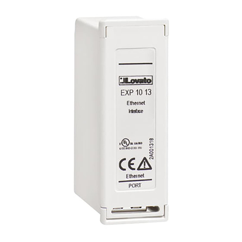
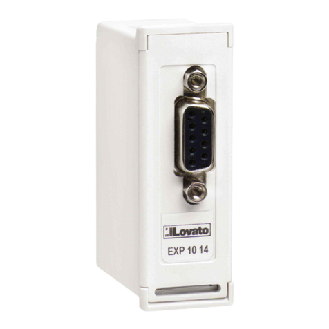
  9. LOVATO ELECTRIC EXP10 13 User manual

LOVATO ELECTRIC EXP10 13 User manual

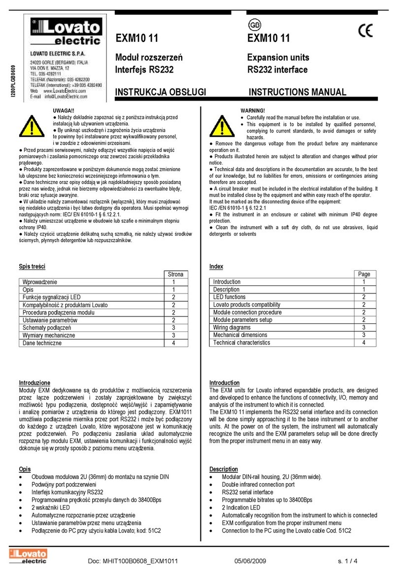
Doc: MHIT101D0508.doc 08/09/2010 p. 1 / 3
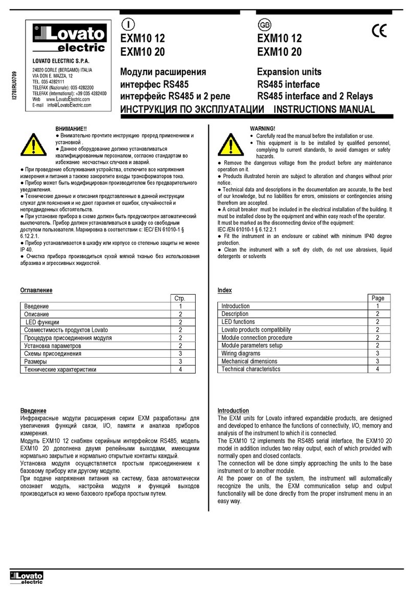
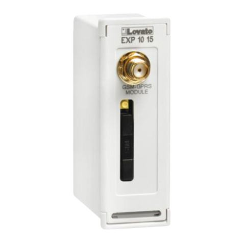
EXP10 13 EXP10 13
Modulo di espansione Expansion module
Interfaccia ETHERNET isolata Isolated ETHERNET interface
MANUALE OPERATIVO INSTRUCTIONS MANUAL
●Prima di qualsiasi intervento sull’apparecchio, togliere tensione dagli ingressi di
alimentazione e dalle uscite relè dove presenti.
●Il costruttore non si assume responsabilità in merito alla sicurezza elettrica in caso
di utilizzo improprio del dispositivo.
●I prodotti descritti in questo documento sono suscettibili in qualsiasi momento di
evoluzioni o di modifiche. Le descrizioni ed i dati a catalogo non possono pertanto
avere alcun valore contrattuale.
●Pulire lo strumento con panno morbido, non usare prodotti abrasivi, detergenti
liquidi o solventi.
●Remove the dangerous voltage from the product before any maintenance
operation on it.
●Products illustrated herein are subject to alteration and changes without prior
notice.
●Technical data and descriptions in the documentation are accurate, to the best
of our knowledge, but no liabilities for errors, omissions or contingencies arising
therefrom are accepted.
●Clean the instrument with a soft dry cloth, do not use abrasives, liquid
detergents or solvents
Introduzione
I moduli di espansione EXP sono stati progettati e sviluppati per potenziare
le funzioni di connettività, I/O, memorizzazione ed analisi dello strumento
base a cui vengono collegati. In particolare il modulo EXP10 13 realizza la
funzione di interfaccia seriare isolata di tipo ETHERNET. Questo modulo
può essere collegato ad un apparecchio Lovato Electric provvisto di slot
per EXP. La connessione evverrà semplicemente inserendo il modulo di
espansione nello strumento principale il quale ne effettuerà
automaticamente il riconoscimento.
L’impostazione dei parametri del modulo viene svolta in modo intuitivo e
semplice nel menù di configurazione presente nel dispositivo principale.
Introduction
The EXP units for Lovato plug in expandable products are designed and
developed to enhance the functions of connectivity, I/O, memory and
analysis of the instrument to which it is connected.
The EXP10 13 implements the isolated ETHERNET serial interface.
Questo modulo può essere collegato ad un apparecchio Lovato Electric
provvisto di slot per EXP. The module connection will be done simply by
plug it in to the expansion slot of the base instrument.. At the power on of
the system, the instrument will automatically recognize the units and the
EXP parameters setup will be done directly from the proper instrument
menu in an easy way.
Descrizione
•Dimensioni compatte (64mmx38mmx22mm).
•Inserimento diretto nello slot di espansione dell’apparecchio.
•Isolamento da 2kVrms per 1minuto dall’apparecchio base.
•Interfaccia di comunicazione ETHERNET 10/100Mbit.
•Protocollo TCP/IP.
•2 LED bi-colore sul connettore RJ45 per lo stato della connessione
ETHERNET.
Description
•Compact size (64mmx38mmx22mm).
•Direct plug in on the base instrument.
•2KVrms for 1 minute of insulation from the base module.
•10/100 Mbps ETHERNET .
•TCP/IP protocol.
•2 status duble-color LED on the RJ45 connector for the
ETHERNET status.
Compatibilità con i prodotti Lovato
Il modulo EXP10 13 può essere abbinato ad un prodotto Lovato Electric
provvisto di alloggiamento per espansione EXP. Verificare la compatibilità
secondo la seguente tabella:
Apparecchio base Rev. SW apparecchio base
DMG800 >= 01
DMG900 >= 00
Lovato products compatibility
EXP10 13 can be connected to a Lovato Electric product fitted by EXP
receptacle slot. Verify the compatibility with the following table:
Base device Base device SW Rev.
DMG800 >= 01
DMG900 >= 00
I296 I GB 0910
ATTENZIONE!!
●Leggere attentamente il manuale prima dell’utilizzo e
l’installazione.
●Questi apparecchi devono essere installati da personale
qualificato, nel rispetto delle vigenti normative impiantistiche, allo
sco
p
o di evitare danni a
p
ersone o cose.
WARNING!
•Carefully read the manual before the installation or use.
•This equipment is to be installed by qualified personnel,
complying to current standards, to avoid damages or safety
hazards.
ATTENZIONE!
●Quando vengono installati i moduli EXP nei multimetri
della serie DMG, è obbligatorio montare i coprimorsetti
piombabili forniti con il multimetro.
WARNING!
•When the EXP. module is installed on a DMG series
multimeter, it is mandatory to install the sealable
terminal block covers supplied with the multimeter.
Doc: MHIT101D0508.doc 08/09/2010 p. 2 / 3
Procedura di connessione del modulo Module connection procedure
1. Rimuovere le tensioni pericolose.
2. Rimuovere i coprimorsetti e la morsettiera estraibile.
3. Rimuovere il tappo di copertura dello slot nel quale si intende inserire
il modulo.
4. Inserire l’EXP10 13 come indicato nella foto in alto.
5. Riposizionare la morsettiera estraibile e montare i coprimorsetti.
6. Alimentare lo strumento principale (verrà riconosciuto il nuovo modulo
di espansione).
NOTA: per togliere il modulo, rimuovere ogni tensione pericolosa e
ripetere in senso contrario le operazioni dal punto 5 al punto 2. Premere
nel punto indicato con * per sganciare il modulo.
1. Remove any dangerous voltage.
2. Remove the terminal covers and the terminal block.
3. Remove the expansion slot cover of the Lovato product at the
position in which the EXP will be plug in.
4. Insert the EXP10 13 as illustrated in the above picture.
5. Replace the terminal block and the terminal cover.
6. Power up the system (the base product will automatically
recognize the expansion unit).
NOTE: Remove any dangerous voltage and repeat the operations from
step 5 to step 2 in the opposite direction. Press in the point indicated by
the * in the picture in order to remove the module.
Funzione dei LED sul connettore RJ45 ETHERNET
POSIZIONE COLORE DESCRIZIONE
LED SINISTRO
(connessione)
Spento
Verde
Ambra
Nessuna connessione
100Mbps
10Mbps
LED DESTRO
(attività)
Spento
Verde
Ambra
Nessuna attività
Full Duplex
Half Duplex
RJ45 connector ETHERNET LED functions
POSITION COLOR DESCRIPTION
LEFT LED
(Link)
OFF
Green
Amber
No link
100Mbps
10Mbps
RIGHT LED
(activity)
OFF
Green
Amber
No activity
Full Duplex
Half Duplex
Programmazione parametri
Per la programmazione dei parametri di configurazione del modulo si
rimanda al manuale dello strumento principale a cui lo si intende collegare.
Rivolgersi ad un amministratore di rete per l’assegnazione dei parametri di
connessione al modulo Ethernet
Module parameters setup
For the EXP parameters configuration, see the manual of the main
product to which it intends to connect.
Refer to network administrator for the Ethernet module parameters
reservation
Dimensioni meccaniche [mm] Mechanical dimensions [mm]
CLAC!
1 2 3
*
Slot Slot Slot Slot
1 2 3 4
Doc: MHIT101D0508.doc 08/09/2010 p. 3 / 3
Caratteristiche tecniche Technical characteristics
Alimentazione Supply
Tensione alimentazione 5V=
(fornita dallo strumento principale)
Supply voltage 5V=
(supplied by main instrument)
Corrente assorbita 250mA Supply current 250mA
Potenza assorbita/dissipata 1,25W Power consumption/dissipation 1.25W
Interfaccia ETHERNET ETHERNET interface
Interfaccia di rete RJ45 Ethernet 10BASE-T or
100BASE-TX (auto-sensing) Network Interface RJ45 Ethernet 10BASE-T or
100BASE-TX (auto-sensing)
Compatibilità Ethernet: Versione 2.0/IEEE802.3 Compatibility Ethernet: Version 2.0/IEEE802.3
Protocolli supportati ARP, UDP/IP, TCP/IP, Telnet,
ICMP, SNMP, DHCP, BOOTP,
TFTP, Auto IP, e HTTP
Protocols Supported ARP, UDP/IP, TCP/IP, Telnet,
ICMP, SNMP, DHCP, BOOTP,
TFTP, Auto IP, and HTTP
Connessione porta ETHERNET ETHERNET port connection
Tipo di connettore RJ45 Connector type RJ45
Connessione al prodotto base Base product connection
Tipo di connettore Connettore ad innesto Terminal type Plug-in connector
Tensione di isolamento Insulation voltage
Tensione nominale di tenuta a impulso
Uimp
4kV Rated impulse withstand voltage Uimp 4kV
Tensione di tenuta a frequenza d’esercizio 2kV Power frequency withstand voltage 2kV
Condizioni ambientali di funzionamento Ambient operating conditions
Temperatura d’impiego -20 - +60°C Operating temperature -20 - +60°C
Temperatura di stoccaggio -30 - +80°C Storage temperature -30 - +80°C
Umidità relativa <90% Relative humidity <90%
Inquinamento ambiente massimo Grado 2 Maximum pollution degree Degree 2
Categoria dì sovratensione 3 Overvoltage category 3
Altitudine ≤2000m Altitude ≤2000m
Contenitore Housing
Dimensioni 64,5mmx38,2mmx22mm Dimensions 64.5mmx38.2mmx22mm
Montaggio Ad inserimento nello slot di
espansione plug in EXP
Mounting For inclusion in the EXP plug in
expansion slot
Materiale Poliammide RAL 7035 Material Polyamide RAL7035
Grado di protezione IP20 Degree of protection IP20
Peso 64g Weight 64g
Omologazioni e conformità Certifications and compliance
Conformità a norme IEC/EN 61010-1:2001, IEC/EN 61000-6-2:2005,
EN 61000-4-3:2006, EN 61000-6-3:2001,
IEC/EN 60068-2-61:1993, IEC/EN 60068-2-78,
IEC/EN 60068-2-6, IEC 60068-2-27.
Reference standards IEC/EN 61010-1:2001, IEC/EN 61000-6-2:2005,
EN 61000-4-3:2006, EN 61000-6-3:2001,
IEC/EN 60068-2-61:1993, IEC/EN 60068-2-78,
IEC/EN 60068-2-6, IEC 60068-2-27

Other LOVATO ELECTRIC Control Unit manuals

LOVATO ELECTRIC EXP10 30 User manual

LOVATO ELECTRIC

LOVATO ELECTRIC EXP10 30 User manual

LOVATO ELECTRIC EXP10 13 User manual

LOVATO ELECTRIC

LOVATO ELECTRIC EXP10 13 User manual

LOVATO ELECTRIC RGK700 User manual

LOVATO ELECTRIC

LOVATO ELECTRIC RGK700 User manual

LOVATO ELECTRIC EXP10 16 User manual

LOVATO ELECTRIC

LOVATO ELECTRIC EXP10 16 User manual

LOVATO ELECTRIC RGAM User manual

LOVATO ELECTRIC

LOVATO ELECTRIC RGAM User manual

LOVATO ELECTRIC EXP10 05 User manual

LOVATO ELECTRIC

LOVATO ELECTRIC EXP10 05 User manual

LOVATO ELECTRIC VLBX C Series User manual

LOVATO ELECTRIC

LOVATO ELECTRIC VLBX C Series User manual

LOVATO ELECTRIC EXM10 12 User manual

LOVATO ELECTRIC

LOVATO ELECTRIC EXM10 12 User manual

LOVATO ELECTRIC VLB X L Series User manual

LOVATO ELECTRIC

LOVATO ELECTRIC VLB X L Series User manual

LOVATO ELECTRIC EXP10 02 User manual

LOVATO ELECTRIC

LOVATO ELECTRIC EXP10 02 User manual

LOVATO ELECTRIC RGK900 User manual

LOVATO ELECTRIC

LOVATO ELECTRIC RGK900 User manual

LOVATO ELECTRIC EXP10 12 User manual

LOVATO ELECTRIC

LOVATO ELECTRIC EXP10 12 User manual

LOVATO ELECTRIC RGK800 User manual

LOVATO ELECTRIC

LOVATO ELECTRIC RGK800 User manual

LOVATO ELECTRIC EXM10 10 User manual

LOVATO ELECTRIC

LOVATO ELECTRIC EXM10 10 User manual

LOVATO ELECTRIC EXP1013 User manual

LOVATO ELECTRIC

LOVATO ELECTRIC EXP1013 User manual

LOVATO ELECTRIC EXM10 00 User manual

LOVATO ELECTRIC

LOVATO ELECTRIC EXM10 00 User manual

LOVATO ELECTRIC EXP10 13 User manual

LOVATO ELECTRIC

LOVATO ELECTRIC EXP10 13 User manual

LOVATO ELECTRIC EXP10 14 User manual

LOVATO ELECTRIC

LOVATO ELECTRIC EXP10 14 User manual

LOVATO ELECTRIC EXP10 00 User manual

LOVATO ELECTRIC

LOVATO ELECTRIC EXP10 00 User manual

LOVATO ELECTRIC EXP10 30 User manual

LOVATO ELECTRIC

LOVATO ELECTRIC EXP10 30 User manual

LOVATO ELECTRIC EXM10 11 User manual

LOVATO ELECTRIC

LOVATO ELECTRIC EXM10 11 User manual

LOVATO ELECTRIC RGK800 User manual

LOVATO ELECTRIC

LOVATO ELECTRIC RGK800 User manual

LOVATO ELECTRIC EXP10 14 User manual

LOVATO ELECTRIC

LOVATO ELECTRIC EXP10 14 User manual

LOVATO ELECTRIC EXP10 14 User manual

LOVATO ELECTRIC

LOVATO ELECTRIC EXP10 14 User manual

Popular Control Unit manuals by other brands

Avnet COM Express MSC C6B-SLH user manual

Avnet

Avnet COM Express MSC C6B-SLH user manual

NI 9231 Getting started guide

NI

NI 9231 Getting started guide

Pittway Fire-Lite Alarms MMF-300 installation instructions

Pittway

Pittway Fire-Lite Alarms MMF-300 installation instructions

Wilcoxon iT401 operating guide

Wilcoxon

Wilcoxon iT401 operating guide

Fike 55-046 Installation and maintenance instructions

Fike

Fike 55-046 Installation and maintenance instructions

OceanAudio 500 series EQ2 Handbook

OceanAudio

OceanAudio 500 series EQ2 Handbook

Mesto Neles XH Series Installation maintenance and operating instructions

Mesto

Mesto Neles XH Series Installation maintenance and operating instructions

AvaLAN AW5800m-SR user manual

AvaLAN

AvaLAN AW5800m-SR user manual

Vimar Eikon 20541 manual

Vimar

Vimar Eikon 20541 manual

Runxin F79A-LCD instruction manual

Runxin

Runxin F79A-LCD instruction manual

Texas Instruments BQ76905 user guide

Texas Instruments

Texas Instruments BQ76905 user guide

Allen-Bradley 1756-L7 Series Reference manual

Allen-Bradley

Allen-Bradley 1756-L7 Series Reference manual

VAT 650 Series Installation, operating,  & maintenance instructions

VAT

VAT 650 Series Installation, operating, & maintenance instructions

RAK WisBlock RAK13007 quick start guide

RAK

RAK WisBlock RAK13007 quick start guide

Transition Networks CWDM-M1631LCR-B quick start guide

Transition Networks

Transition Networks CWDM-M1631LCR-B quick start guide

Supermicro AOC-ATG-i2T2SM user guide

Supermicro

Supermicro AOC-ATG-i2T2SM user guide

Burkert 7012 Series operating instructions

Burkert

Burkert 7012 Series operating instructions

ZKTeco SLK20S user manual

ZKTeco

ZKTeco SLK20S user manual

manuals.online logo
manuals.online logoBrands
  • About & Mission
  • Contact us
  • Privacy Policy
  • Terms and Conditions

Copyright 2025 Manuals.Online. All Rights Reserved.