Gazebo penguin W1608-32 User manual

ZZZ-188.W1608-32.1127-15.GP.EN.HER.doc HER-HP 1
W1608-32
8 X 16 SOLARIUM
ASSEMBLY INSTRUCTIONS
Two or more adults required for assembly
Requires 96” clearance at the wall
Base Dimensions 190’’x 94 1/2’’, Largest Dimensions 190’’x98 1/2’’ (see pg.14)
adlonco@hotmail.com

ZZZ-188.W1608-32.1127-15.GP.EN.HER.doc HER-HP 2
TOOLS REQUIRED:
Screwdriver (Philips #2)
Knife
File (smooth)
Needle-nosed pliers
Rubber mallet
Step ladder (minmum 6' in height)
Spatula
Power drill
Tube of silicon
Drill bit 5/16" cement
(according to surface)
BEFORE STARTING:
Ensure that you have a solid base,
such as concrete or wooden deck,
not slanted more than 1” per 8’.
Avoid installing unit adjacent to trees
or a sloped roof, as snow and ice may slide
onto the solarium and cause it to collapse.
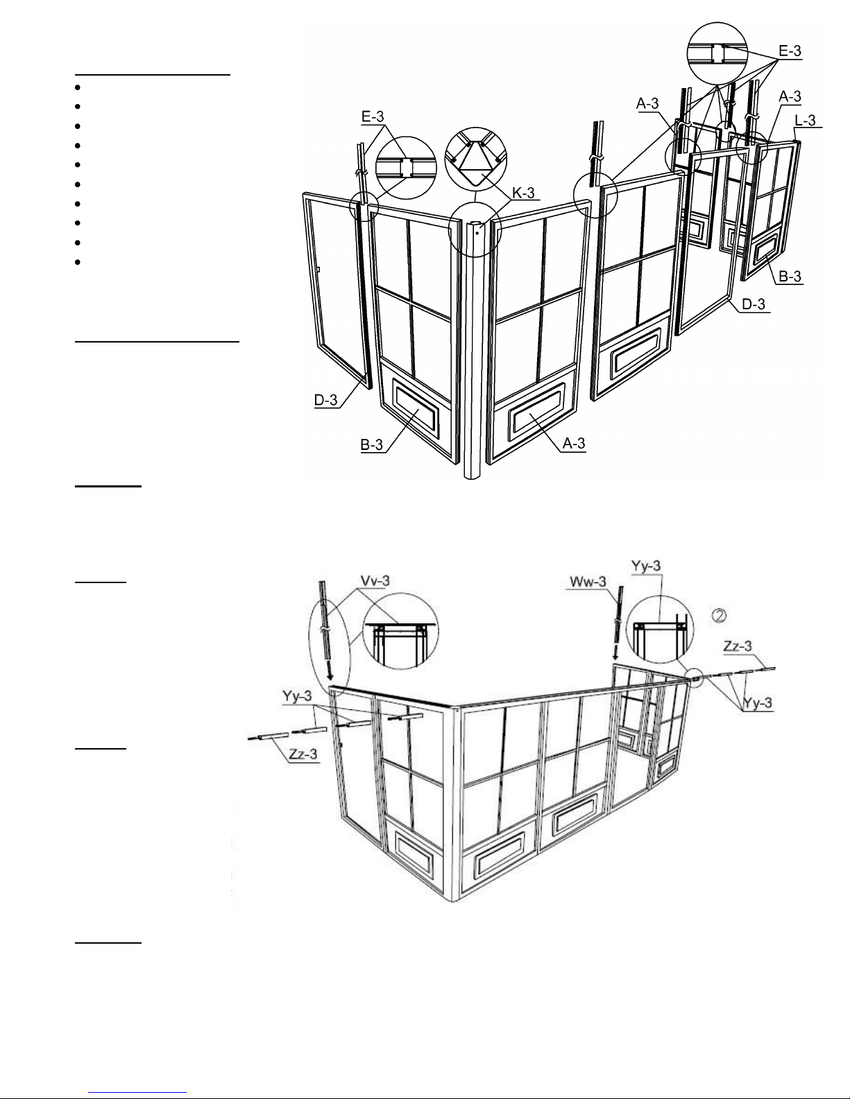
STEP #1
Decide the position of the door frames before assembly according to where you intend to slide the door. At
the front of the solarium, use frame D3 for the opening of the door and B3 for the direction of the door when
open. Use E3 between frame ends and use two (2) K3 joints for corners.
NOTE:
When placing the door frame
opening, make sure the inserts
on the frame are on the inside
and on the upper half of the
frame of the solarium because
the door will be set on the inside
due to clearance.
NOTE:
When sliding the connectors,
shake the frame so that they
will slide easily. Do not use
tools to force. If needed, clean
paint with a file and make sure
the ends of the frame and joints
are not bent or warped. If so,
use the needle-nosed pliers to
straighten.
STEP #2
Slide the vertical guides Vv-3 left and Ww-3 right into the 2 ends of the frames along the grooves, shaking
while sliding for easier movement. Next, slide three (3) Yy-3 and one (1) Zz-3 from left side to right on top
of the frame. The groove should be towards the interior of the unit. Repeat from right side and space evenly.

ZZZ-188.W1608-32.1127-15.GP.EN.HER.doc HER-HP 3
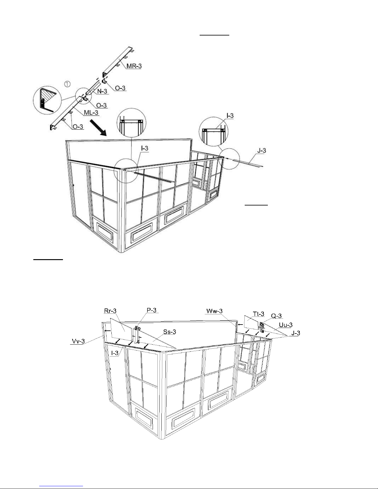
STEP #4
Set polycarbonate exposed side on the outside over horizontal left guide I-3, use one (1) Rr-3 panel, one (1)
P-3 joint and one (1) Ss-3 panel, then do the right side with one (1) Tt-3 panel, one (1) Q-3 joint and one (1)
Uu-3 panel over the J-3 horizontal panel. Secure P-3 and Q-3 to I-3 and J-3 respectively with self-tapping
screws (PQ-3).
NOTE:
Once the wall track is in place,
apply silicon along the top of the
wall track and at the joint of the
two tracks. Silicon is not
supplied.
ASSEMBLE PIECES
BEFORE SCREWING
THEM TO THE WALL
STEP #3
Assemble ML-3, N-3, O-3, and MR-3 as shown and
position evenly above vertical guides, with the top fo
the track at 96’’ from the ground. Secure wall track
and vertical tracks to brick or cement wall by drilling
through the aluminum and using screws Xx-3. Insert
the 2 horizontal guides, I3 & J3 at the top of the
frame. Make sure the 2 frames are at the correct
level, if not, use shims to compensate. Do not use
tools to force.

ZZZ-188.W1608-32.1127-15.GP.EN.HER.doc HER-HP 4
ÉTAPE #6
Placez les chevrons U-3 sur les
derniers crochets grâce aux vis Bb-
3 sur la partie supérieure et vissez
manuellement deux (2) vis Z-3 sur
le cadre. N’utilisez pas le foret
électrique.
STEP #5
Set right rafter T-3 over last bracket
then secure it with Bb-3 screw and
continue screwing through joint K-3
with the Bb-3 screw. Secure to Q-3
bracket with self-tapping screw
(PQ-3). Repeat on left side with
rafter S-3.
STEP #6
Set U-3 rafters over the middle of each
panel with Bb-3 screws at the top and
two (2) Z-3 screws over the brackets
on frame manually. Set U-3 rafter on
each joint and use Z-3 screws
manually. Do not use power drill.

ZZZ-188.W1608-32.1127-15.GP.EN.HER.doc HER-HP 5
STEP #7
Remove protective film from two (2) sides of each panel and make sure the top side of the panel faces the
sunlight. Insert and slide on the top groove of the rafters all the way to the end. Pp-3 should go first and last with
the Qq-3 panels in between.
STEP #8
Insert the aluminum middle roof joint between the rafters, making sure the slotted holes are at the bottom. Slide
into upper and lower grooves of the rafters then slide all the way into the panels. Make sure the panels are inside
the aluminum middle roof joint groove. Insert a V-3 at either end, then insert all W-3 and then the remaining V-3.
Tap gently with rubber mallet if needed.

ZZZ-188.W1608-32.1127-15.GP.EN.HER.doc HER-HP 6
STEP #9
Insert the second row of panels into the lower groove on the rafter. Slide panels until they reach the aluminum
pieces between the panels and gently tap on the panel to guide it into the aluminum groove. Use a spatula if
needed to make it fit. Insert two (2) Pp-3 on either end, then insert the Qq-3 panels.
STEP #10
Starting at either end, add X-3 edging and one (1) R-3 bracket and screw with Bb-3 manually, do not use power
drill. Add Y-3 edging and repeat until you reach the end, then add the X-3 edging.

ZZZ-188.W1608-32.1127-15.GP.EN.HER.doc HER-HP 7
STEP #11
On the inside of the solarium under each rafter there are two rows of inserts with threads. Start the upper row
with a Jj-3 at either end and screw it with Ff3 and in between the Kk-3 panels. Use Ff-3 screws at the lower row
Ll-3 at the 2 ends then the others in between the Mm-3 panels. Make sure screws are manually tight.
STEP #12
DOOR UNIT(S) MUST BE
ASSEMBLED INSIDE OF
SOLARIUM.
Slide upper door track F-3 into
wheels of sliding door C-3. Slide
lower door track G-3 and make
sure inserts are close enough to
the frame to attach. Use bolt
Bb-3 to affix the plastic stopper
H-3 on each end of top door rail
F-3. Use Oo-3 screws to affix
upper door rail and cap Nn-3, at
each end of top rail door.

ZZZ-188.W1608-32.1127-15.GP.EN.HER.doc HER-HP 8
STEP #13
Lift up door and track inside of solarium then set it over the door opening by screwing at the top. First use bolts
(Ww) and washers (Gg-3) on the inside and female bolts (Cc-3-2) on the outside for the top assembly. See
diagram below. Attach lower track with bolts (Cc-3) and washers (Gg-3). Set up door latch on the side required
for your door to lock, adjust latch as required.
Sliding door
should be
installed from
the inside of
the solarium.
Sliding door
should be
installed
from the
inside of the
solarium.
Ww

ZZZ-188.W1608-32.1127-15.GP.EN.HER.doc HER-HP 9
STEP #14
Anchor the solarium to the deck or floor securely using screws and shields supplied. See
diagram below.
SPECIAL NOTES
To remove a screen, remove the two
(2) screws at the top of the frame then
pull sideways to the opposite end of the
handles to remove. To remove wind
panels, push or pull to one side, making
sure that locking pin is not locked then
remove panels gently, panels are easy
to remove.
NOTE:
This unit is not waterproof. For best
protection against rain, close the
windows of each frame with the outside
window in the center, and the inside
window at the top.
CLEANING INSTRUCTIONS:
Use only mild or warm soapy water, no
strong or abrasive cleaning products.
Be sure to remove heavy snow and/or
ice.
WARNING:
1) Do not use BBQ or any other
flammable product inside the
solarium.
2) Remove snow from the roof.

ZZZ-188.W1608-32.1127-15.GP.EN.HER.doc HER-HP 10
SOLARIUM W1608
DESCRIPTION
QTY
DRAWING
DESCRIPTION
QTY
DRAWING
10-496-32
REGULAR FRAME
A-3
4
10-497-32
FRAME NEXT TO
DOOR B-3
(with extra holes)
2
10-498-32
SLIDING DOOR
C-3
2
10-499-32
SLIDING DOOR
FRAME
D-3
2
11-544-32
CONNECTING
PIECE
E-3
10
11-545-32
TOP DOOR RAIL
F-3
2
11-546-32
BOTTOM DOOR
RAIL
G-3
2
08-138-32
PLASTIC
STOPPER
H-3
4
10-500-32
LEFT SIDE
RECEIVER
I-3
1
10-501-32
RIGHT SIDE
RECEIVER
J-3
1
10-502-32
CORNER
CONNECTOR
K-3
2
10-532-32
TRACK
ML-3
1
10-533-32
TRACK
MR-3
1
10-505-32
TRACK JOINT
N-3
1
10-506-32
RAFTER
BRACKET
O-3
6
10-507-32
LEFT GABLE
JOINT
P-3
1
10-508-32
RIGHT GABLE
JOINT
Q-3
1
10-509-32
ROOF RAFTER
CAP
R-3
9

ZZZ-188.W1608-32.1127-15.GP.EN.HER.doc HER-HP 11
DESCRIPTION
QTY
DRAWING
DESCRIPTION
QTY
DRAWING
10-510-32
LEFT SIDE
RAFTER
S-3
1
10-511-32
RIGHT SIDE
RAFTER
T-3
1
10-512-32
REGULAR
RAFTER
U-3
7
10-513-32
MIDDLE ROOF
JOINT
V-3
2
10-514-32
MIDDLE ROOF
JOINT
W-3
6
10-515-32
EDGING
X-3
2
10-516-32
EDGING
Y-3
6
08-156-32
SCREW
Z-3
14
08-158-32
BOLT
Bb-3
32
08-161-32
BOLT
Cc-3
12
12-037-32
FEMALE BOLT
Cc-3-2
12
08-165-32
RIGHT DOOR
LATCH
Dd-R-3
2
08-169-32
LEFT DOOR
LATCH
Dd-L-3
2
08-167-32
SCREW
Ee-3
12
08-168-32
BOLT
Ff-3
20
08-187
WASHER
Gg-3
28
08-193
PLASTIC PLUG
Ii-3
12
10-517-32
END ROOF
CROSS BAR
Jj-3
2

ZZZ-188.W1608-32.1127-15.GP.EN.HER.doc HER-HP 12
DESCRIPTION
QTY
DRAWING
DESCRIPTION
QTY
DRAWING
10-518-32
REGULAR ROOF
CROSSBAR
Kk-3
6
10-519-32
ROOF TOP
REINFORCE
Ll-3
2
10-520-32
ROOF TOP
REINFORCE
Mm-3
6
08-134-32
UPPER DOOR
RAIL END CAP
Nn
4
08-135-32
SCREW
Oo-3
8
10-521
( 51 ½” X 24 ½”)
LEFT+RIGHT
ROOF PANEL
Pp-3
4
10-522
( 51 ½” X 23”)
REGULAR ROOF
PANEL
Qq-3
12
10-523
LEFT BACK
GABLE PANEL
Rr-3
1
10-524
LEFT FRONT
GABLE PANEL
Ss-3
1
10-525
RIGHT BACK
GABLE PANEL
Tt-3
1
10-526
RIGHT FRONT
GABLE PANEL
Uu-3
1
10-527-32
LEFT WALL
GUIDE
Vv-3
1
10-528-32
RIGHT WALL
GUIDE
Ww-3
1
10-529
SCREW FOR
FIXING TO
WALL
Xx-3
26
10-530-32
REGULAR TOP
FILLER
Yy-3
6
10-531-32
END TOP
FILLER
Zz-3
2
12-047-32
BOLT
Ww
12
(M5*15mm)
13-045
SELF-TAPPING
SCREW
PQ-3
4

ZZZ-188.W1608-32.1127-15.GP.EN.HER.doc HER-HP 13
AVAILABLE REPLACEMENT PARTS
DESCRIPTION
DRAWING
DESCRIPTION
DRAWING
10-435-32
PVC WINDOW
(in frame)
85-417-S
ROUND SPLINE FOR
SCREENING
10-493
PVC WINDOW
(replacement
material only)
11-824-32
BOTTOM PLASTIC
PANEL (for wall
panels)
85-417-P
ROUND SPLINE
FOR PVC
WINDOW
11-825-32
BOTTOM PLASTIC
PANEL (for doors)
15-123-32
PIN FOR PVC
WINDOW
15-097-32
DOOR WHEEL
ASSEMBLY
13-055
PC WINDOW (for
sliding door)
10-458
REPLACEMENT
WEATHERSTRIP
124”
12-174-32
MOSQUITO
SCREEN (in
frame)
15-126-32
MOUNTING
BRACKET FOR
RAFTER (U-3)
85-014
REPLACEMENT
SCREENING (no
frame)

ZZZ-188.W1608-32.1127-15.GP.EN.HER.doc HER-HP 14

ZZZ-188.W1608-32.1127-15.GP.EN.HER.doc HER-HP 15
MAINTENANCE NOTES
1. In case of a defective or damaged part, or for any other questions concerning the product,
please contact the manufacturer directly.
2. Please have the parts list and part numbers on hand when ordering or requesting
replacement parts.
3. The product should not be installed adjacent to trees or a sloped roof. Snow and ice may
slide onto the roof and cause it to collapse.
4. While the product is designed for 4 seasons use, the roof must be kept free of
accumulation of snow.
ONE YEAR LIMITED WARRANTY
This product has been designed and manufactured to meet the highest standards of quality and
durability. Subject to the Conditions for Exercising the Warranty and the Limitations on the
Warranty set forth below, it is warranted to be free of material and manufacturing defects for a
period of one year from the date of purchase. Should the product become damaged, or the
warranty period has expired, please contact Gazebo Penguin Customer Service Department for
a complete schedule of replacement parts and prices.
CONDITIONS FOR EXERCISING THE WARRANTY
In order to properly exercise your warranty, please comply with the following:
Carefully inspect the contents of the carton for missing or damaged components. Should
you discover damaged or missing parts, do not return the product to the place of
purchase, but contact Gazebo Penguin Customer Service Department at the numbers
listed below:
Montreal: (514) 276-3485
Elsewhere: 1-800-737-7174
NOTE: Damages/missing parts must be reported within 30 days of delivery.
LIMITATIONS ON THE WARRANTY
1. The product is not warranted against damages due to vandalism, abuse, falling or thrown
objects, or accumulation of snow.
2. The product is not warranted against damages due to extreme weather conditions, such
as thunderstorms, hail, strong wind or snow storms, or any other acts of God.
3. The product is only warranted in the event it is installed in accordance with the Gazebo
Penguin’s written instructions enclosed with the product.
4. The product is not warranted in the event it has been improperly anchored.
5. We reserve the right to replace or repair any defective product or parts at our discretion.
Table of contents
Other Gazebo penguin Greenhouse Kit manuals
Popular Greenhouse Kit manuals by other brands

Grandio
Grandio Ascent 8x8 KIT user manual

Sunnydaze Decor
Sunnydaze Decor GH-006 Assembly instructions

Palram Applications
Palram Applications Snap & Grow 8x8 instructions

Sproutwell
Sproutwell SMALL GAZEBO Assembly instructions

ClearSpan
ClearSpan 36' Wide Pony Wall Building instruction manual

GrowSpan
GrowSpan 2000 Series manual

Greenhouse Megastore
Greenhouse Megastore Caterpillar Tunnel Assembly instructions

VOLYA
VOLYA Alfa Assembly manual

ACD PRESTIGE
ACD PRESTIGE MS1 L Series manual

Palram
Palram CANOPIA HARMONY 6x4 / 2x1.3 How to assemble

Elite Greenhouses
Elite Greenhouses TITAN 1200 Instructions & Illustrations

Juliana
Juliana Orangeri Assembly instructions