GBC SmartPunch Plus User manual

Sharp SmartPunch Plus Installation Manual 1
Sharp SmartPunch™ Plus
Installation Manual
Contents Page
1. Recommendations and Pre-requisites 2
2. Unpacking 2
3. Configurations 2
4. Sheet guides installation 3
5. Docking Bracket Installation 4
6. Cable connections 5
7. Leveling & Height Adjustment 9
8. Final Steps 10
Part No. 7724542
Rev No. C1
Issue Date: June, 2021
ACCO Brands, Inc.
Four Corporate Drive
Lake Zurich, IL 60047
www.acco.com

Sharp SmartPunch Plus Installation Manual 2
1. Recommendations and Pre-requisites
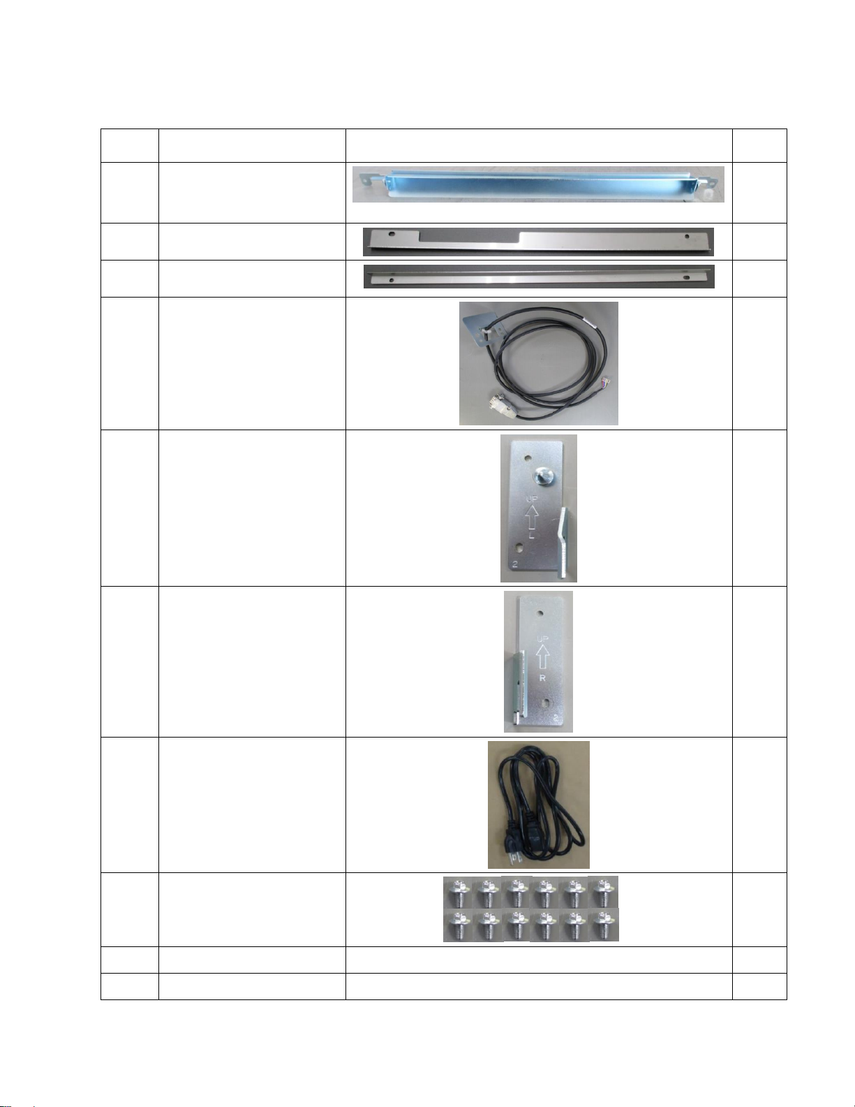
You will need the installation kit provided with the SmartPunch Plus unit, which can be found in the
main carton.
2. Unpacking
Inspect the outside of the package for shipping damage. If there is evidence of shipping damage,
contact the shipping carrier immediately.
Remove the punch from its shipping carton. Three people are recommended, one lifting at the casters
while two lift at the top cover. DO NOT lift using the front door panel.
Retain the smaller accessory box; it contains parts required for correct installation of the SmartPunch
Plus.
Inspect for any concealed damage to the unit. If there is evidence of concealed shipping damage,
contact the shipping carrier immediately.
Remove all shipping tape from doors and levers.

Sharp SmartPunch Plus Installation Manual 3
3. Installation Kit Contents
No.
Description
Picture
Qty
1
Entrance Guide
1
2
Exit Upper Guide
1
3
Exit Lower Guide (Angled
type)
1
4
Communication Cable
Assembly
1
5
Left Docking Bracket
1
6
Right Docking Bracket
1
7
Power Cord
115V: US
230V: UK, Swiss, and EU
1
8
M4-8mm long Round
Tipped Screw
12
9
Installation Manual
1
10
User Manual
1

Sharp SmartPunch Plus Installation Manual 4
4. Sheet guides installation
4.1 Entrance side guides
Install the entrance guide provided in the Installation kit with the supplied M4-8mm long round tipped screws (2
Nos.).
When Installing the SmartPunch Plus downstream from the MX-CF11(Inserter Unit), the following procedures are
needed before installing the entrance side guides.
i) Remove the screws from both ends.
ii) Attach the black Mylar from the MX-CF11 parts kit to the lower bracket at the reference edge. shown
in the image. Once complete re-assembly the bracket for installation.
Before
After

Sharp SmartPunch Plus Installation Manual 5
4.2 Exit side guides
Install the Angled Exit guide with the supplied M4-8mm long round tipped screws (2 places)
Attach exit upper guide with the supplied M4-8mm long round tipped screws

Sharp SmartPunch Plus Installation Manual 6
5. Docking Bracket Installation
The docking brackets are shipped in a
separate bag along with M4-8mm long
round tipped mounting screws (not
shown).
Install the supplied docking brackets as
shown with the bracket marked “R” on
the right side facing you as you look at
the exit side of the upstream device.
Install the bracket marked “L” on the left
side facing you. Both brackets should
be oriented with the arrow facing up.
When installing the SmartPunch Plus downstream from the MX-RB18(Curl
Correction Unit)
When Install the SmartPunch Plus downstream to MX-CF11(Inserter Unit)

Sharp SmartPunch Plus Installation Manual 7
6. Cable connections
Power OFF the entire system before making the connections.
It is important to turn OFF the main power switch inside the front door of the printer.
a)
i) Remove the finisher rear maintenance cover and plug the 7 pin communication cable to CN145 on
the finisher control board. The communication cable is provided in the Installation kit of
SmartPunch Plus.
ii) Attach the bracket tied to the communication cable with the supplied M4-8mm long round tipped
screws (2 places).

Sharp SmartPunch Plus Installation Manual 8
b) Plug the free end of the communication cable to the communication port of the SmartPunch Plus in the rear
side of the machine.
c) Replace the finisher rear maintenance cover. Ensure that the communication cables are not pinched anywhere.
d) Connect the supplied AC power cable to the SmartPunch Plus on the rear side lower left corner.
SmartPunch Plus has a power switch on the front of the machine. Ensure this is turned on.
7. Leveling & Height Adjustment
7.1 Height Setting
No height adjustment of the SmartPunch Plus is required for an installation site with a level floor. If the floor
is uneven then it is recommended to set the level of the SmartPunch Plus using the upstream device as a
reference.

Sharp SmartPunch Plus Installation Manual 9
7.2 Adjusting the Casters
a)
Using a 19mm (3/4”) open ended wrench, loosen
the jam nut(s) situated on the caster stud under the
base of the machine.
b)
Using the 17mm (11/16”) wrench, rotate the caster
stems to change the height.
Re-tighten the jam nuts once the correct height is
achieved.
8. Final Steps
8.1 Printer & Finisher Firmware
Confirm that the printer and finisher have the latest firmware installed. Firmware is available for download
at
8.2 Enabling the Punch Icon
The power switch for the SmartPunch Plus can be found on the front frame on the lower right position
(shown below). Turn the SmartPunch Plus on before the main unit.
The Punch icon (shown below) will appear automatically if the connections are made correctly and the
power is cycled.

Sharp SmartPunch Plus Installation Manual 10
8.3 SmartPunch Plus settings
In the SmartPunch Plus LCD go to setup up options and select either ISO or ANSI.
8.4 Functional Test
Functional test the SmartPunch Plus/ MP system
a) Check to ensure that the paper chip tray is securely in place.
b) Check to ensure that a die set is installed properly and that any extra die sets are securely stored in
the die storage area.
c) Run a small test job in “Bypass” mode. Check to ensure that the job is not punched and bypasses
properly.
d) Run a small job with punch enabled. Check the punched holes of the job.
e) If the customer has a perf or crease die test those as well.
f) Run each die set to punch 100 sheets or until there is no oil residue around the holes.
8.4 User manual
Print a copy of SmartPunch Plus User manual from the supplied CD and leave it at the install location.
Table of contents