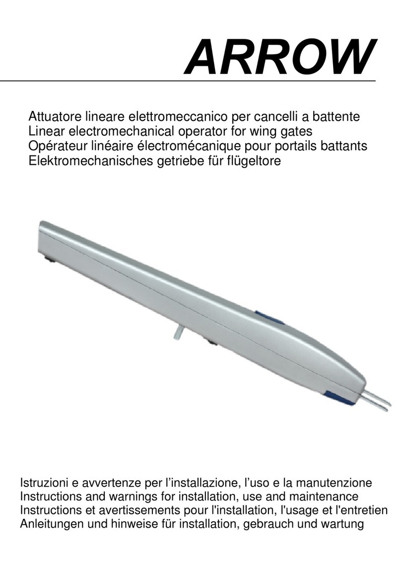
GBD ENTRA EB User manual

1
ENTRA EB
ENTRA EB
SWING DOOR OPERATOR
INSTALLATION MANUAL
ENGLISH

2
ENTRA EB
Thank you for choosing this product. For best automatism performance, we recommend you carefully read
and follow the installation and use instructions found in this manual. Installation of this automatism must
only be performed by the professionally qualified personnel for whom this manual is addressed. Any errors
during installation may be harmful to people or things. Packaging material (wood, plastic, cardboard, etc.)
should not be scattered in the environment or left within the reach of children as potential sources of danger.
Every installation phase must be performed in accordance with the regulations in force and following Good
Technique standards. Before beginning installation make sure that the product is integral and has not been
damaged during transportation or by poor storage conditions. Before installing the product make sure that
each architectural and structural element of the entrance (girder fastening surfaces, casings, guide, etc.) is
appropriate and sufficiently robust to be automated. Conduct a careful risk analysis and make suitable
modifications to eliminate conveyance, crushing, cutting and hazardous areas in general. Do not install the
product in environments where gas, steam or inflammable fumes are present. The manufacturer is not liable
for any neglect of “good technique” or specific regulations in the construction of the casing to be motorized
and any collapse of the same. All automatic entrance safety and protection devices (photocells, active
sensors, etc.) must be installed in accordance with the regulations and directives in force, with the completed
risk analysis, system type, use, traffic, forces and inertia in play. Pay careful attention to area where the
following may occur: crushing, cutting, conveyance and any other type of hazard in general applying, if
necessary suitable indications. Indicate the motorized door identification information on every installation.
Make sure that the upstream electrical system is correctly dimensioned and has all the opportune protections
(circuit breakers and fuses). Only use original spare parts in maintenance and repairs. Do not tamper or alter
devices in the automatism and all the safety devices in the control panel for any reason. The manufacturer is
not liable if parts within the automatism are altered or tampered with or if safety devices other than those
indicated by the manufacturer are used in the system. The automatism installer must provide the automatic
entrance manager with the use manual and all the information required for correct use in automatic and
manual modes (even for electronic locking) and in the event of emergency. Pay careful attention to the
messages in this manual that are marked with the hazard symbol. They can either be warnings aimed at
avoided potential equipment damage or specific signals of potential hazard to the installer and others. This
device was designed to automate pedestrian swinging doors. Any other use is considered contrary to the
use foreseen by the manufacturer who therefore shall not be held liable.
Before carrying out any operation it is necessary to read this manual carefully and follow all the
instructions, with particular attention to those indicated by the following references:
DANGER:
indications that, if not followed scrupulously, could generate sources of
danger or death
ATTENTION:
indications that, if not followed scrupulously, could generate
malfunctions

3
ENTRA EB
SUMMARY
Warnings for the installer –Recycling and disposal.........................................................................4
Intended use –Application limits –Low energy –Preliminary checks............................................5
Machine Directive ............................................................................................................................6
Technical features ............................................................................................................................7
Dimensions and general specifications............................................................................................8
Arms .................................................................................................................................................9
Remove cover and preparation of the operator’s installation ......................................................10
Slide arm installation (pull) .......................................................................................................11-22
Articulated arm installation (push) ...........................................................................................23-34
Modification spring pre-charge......................................................................................................35
Spring recharge –Selection brake level.........................................................................................36
Power kit installation.................................................................................................................37-38
Power connection ..........................................................................................................................39
Control board ............................................................................................................................40-43
Dip switches....................................................................................................................................44
Electric locks..............................................................................................................................45-47
Commissioning ..........................................................................................................................48-49
Security sensors and safety devices installation.......................................................................50-53
Parameters adjustment.............................................................................................................54-59
Status report...................................................................................................................................59
Errors ..............................................................................................................................................60
Operating logics.........................................................................................................................61-62
Wiring and use double ENTRA EB (S/M) ...................................................................................63-67
Interlock wiring and use............................................................................................................68-69
Troubleshooting .............................................................................................................................70
Sensors 4Safe on SW - wiring.........................................................................................................71
Sensors Lzr-flatscan sw - wiring .....................................................................................................72
Sensors 4Safe on SW - wiring - wiring using master/slave cable between the two sensors.........71
Sensors Lzr-flatscan sw - wiring - wiring using master/slave cable between the two sensors .....72
Use and maintenance manual...................................................................................................75-82

4
ENTRA EB
1. WARNING FOR THE INSTALLER (GENERAL SAFETY
OBLIGATIONS)
1) It is important for the personal safety to install the automatism in accordance with the
instructions. Incorrect installation or incorrect use of the product can lead to serious personal injury.
2) Read carefully the instructions before starting to install the product.
3) Keep the instructions for future reference.
4) This product was designed and built exclusively for the use indicated in this documentation. Any
other use not expressly indicated could compromise the integrity of the product and /or represent
a source of danger.
5) ED declines any responsibility deriving from misuse or use other than that for which the
automatism is intended.
6) Do not install the appliance in an explosive atmosphere: the presence of flammable gases or
fumes is a serious safety hazard.
7) ED is not responsible for failure to observe Good Technique in the construction of the closing
elements to be motorized, as well as for any deformation that may occur during use.
8) Before carrying out any work on the system, disconnect the power supply.
9) Check that there is a differential switch upstream of the system.
10) Check that the earth installation is done in a workmanlike manner.
11) The safety devices (EN 12978 standard) protect any dangerous areas from mechanical
mouvements risks, such as crushing, conveying, shearing.
12) For maintenance use only GIBIDI parts.
13) Do not make any modifications to the components that are part of the system.
14) The installer must provide all information relating to the manual operation of the system in the
event of an emergency.
15) The user must not attempt any kind of repair or direct intervention and contact only qualified
personnel.
16) Installation must be carried out only by qualified and experienced personnel and in full
compliance with current regulations.
17) Anything not expressly provided for in these instructions is not permitted.
18) This manual is intended for professional installers or competent persons only.
RECYCLING AND DISPOSAL
This product is built with different materials. The major parts (aluminum, plastic, iron, wires) are solid
urban waste. They can be recycled through collection and disposal in authorized centers. Other
components (control boards, etc.) may contain pollutants. They need to be removed and hand over to
companies authorized to recover and dispose them. The packaging (paperboard, plastics etc.) are solid
urban waste and they can be disposed of without any problem, simply performing waste collection for
recycling. Before proceeding it is always recommended to verify local specific norm for disposal.
PLEASE RECYCLE!

5
ENTRA EB
2. INTENDED USE
DANGER: The ENTRA EB automation must be used exclusively for the movement of pedestrian
swing doors.
The automatism for hinged doors is a monobloc composed of an electromechanical device that
allows the opening and closing of the door to be controlled by means of a trasmission arm.
The door is opened / closed by a spring /motor system or closed only by a spring in the event of a
power failure. Inside the protection casing there is also the electronic control device that allows to
program and control the operation of the system.
3. APPLICATION LIMITS
DANGER: For a correct application of the automatism the door must not exceed the weight
and the width indicated in the diagram of Fig.2. Each transmission arm also corresponds to a
different maximum depth value of the jamb above which it is not possible to correctly install the
system. The automatism is designed exclusively for the normal operation of swing doors in dry
environments, and must be installed inside buildings. Entrance Dynamics declines all responsibility
for any damage deriving of any application or use outside the intended purposes and from
unauthorized modifications.
4. LOW ENERGY
ENTRA EB can be set in the order to meet requirements of Low-Energy application according EN16005.
- reduced dynamic force;
- low speed;
- reduced dynamic/static force.
It is installer's responsibility to verify the compliance of the installation Low-Energy compared with current
standards. The protection of the closing edge must be assessed individually.
5. PRELIMINARY CHECKS
Before installing the automatism please check:
–verify the installation does not create dangerous situations;
–prearrange proper pipes and conduits for the wires, granting the protection of the same against mechanical
damages;
–the surface where fixing the automatism has to be resistant. Use screws, bolts, etc. adequate to the type of
surface;
–the structure of the door has to be strong to hold the weight of the automatism as well the hinges, also
check to not have friction between fixed and mobile parts;
–use proper equipment and tools to install in security and in accordance with the regulations.

6
ENTRA EB
7. TECHNICAL FEATURES
DIMENSIONS
587x120x95mm
POWER SUPPLY
230V ±10% AC 50/60Hz
RATED POWER
85W
NIMINAL MOTOR TORQUE
35Nm
EXTERNAL DEVICES POWER
15Vdc - 12W MAX
OPENING TIME
3s ÷ 6s (70°/s ÷ 20°/s)
CLOSING TIME
4s ÷ 15s (40°/s ÷ 10°/s)
CLOSING FORCE (ACCORDING EN 1154)
EN3 ÷ EN6
MAX. OPENING ANGLE
110°
WING DIMENSION
600 ÷ 1400 mm
WEIGHT MAX. WING
See chart
WORKING TEMPERATURE
from -10°C to +55°C
ANTI-CRUSHING
Automatic traction restriction in
presence of obstacles
WEIGHT
9 kg
SERVICE
Continuos
PROTECTION
IP40
SOUND PRESSURE LEVEL (LpA)
≤70dB (A)
DEVICE EQUIPPED WITH SPRING OPENING IN THE EVENT OF LACK OF ELECTRICITY, SEE SECTIONS
WARNINGS AND INTENDED USE.
WING
(mm)
WEIGHT
(kg)
600
420
700
310
800
240
900
190
1000
150
1100
130
1200
110
1300
90
1400
80

7
ENTRA EB
8. DIMENSIONS AND GENERAL SPECIFICATIONS
01
Base Plate
02
Drive system (motor/gear/spring)
03
Main control board
04
Switching power supply unit
05
End cap with Internal program switch and ON/OFF switch
06
Cover
07
Battery back up (optional)
08
Kit axle extensions H=50mm (optional)
09
Kit axle extensions H=70mm (optional)
10
Kit axle extensions H=90mm (optional)

8
ENTRA EB
9. ARMS
A
Slide arm: pull arm installation –for lintel depths +50mm –100mm
B
Standard arm: push arm installation –for lintel depths max. -150mm
C
Long arm: push arm installation -for lintel depths max. -300mm
FOR A CORRECT POSITIONING PLEASE REFERS TO PARAGRAPH “ARM INSTALLATION”

9
ENTRA EB
10. REMOVE COVER AND PREPARATION OF THE OPERATOR’S INSTALLATION
Unscrew “A” and remove the cover
Preparation 1: use adhesive template Preparation 2: use base plate as template
and NOT remove components removing components
Template to stick on the
wall/frame
Base plate to use as
template

10
ENTRA EB
11. SLIDE ARM INSTALLATION (PULL)
The rigid arm is used for doors that open on the same side as the automatism installation.
Axle extensions
position “C”
L=30mm
(Standard already welded to arm)
42mm
L=50mm
(Standard +
Kit axle extensions H=50mm)
62mm
L=70mm
(Standard + Kit
axle extensions H=70mm)
82mm
L=90mm
(Standard +
Kit axle extensions H=90mm)
102mm

11
ENTRA EB
WING OPENING LEFT - dimension and fixing of the automatism:
Use the adhesive template for the fixing holes. The Holes must be adequate for the type of screw
used. For the passage of cables, make holes in the areas indicated in the image.
Opening left
Area for cables passage
Area for cables passage
For correct positioning, always use the axis of the hinges of the door as main reference.

12
ENTRA EB
Fix the automation using the holes made previously.
For correct assembly, the base must be
aligned with the hinge axis.
ATTENTION!!!!
For LEFT OPENING the automatism must be
ALWAYS be fixed with
MOTOR ON THE RIGHT.

13
ENTRA EB
WING OPENING RIGHT - dimension and fixing of the automatism:
Use the adhesive template for the fixing holes. The holes must be adequate for the type of screw
used. For the passage of cables, make holes in the areas indicated in the image.
Opening right
Area for cables passage
Area for cables passage
For correct positioning, always use the axis of the hinges of the door as main reference.

14
ENTRA EB
Fix the automation using the holes made previously.
For correct assembly, the base must be
aligned with the hinge axis
ATTENZION!!!!
For RIGHT OPENING the automatism
must be ALWAYS be fixed with
MOTOR ON THE LEFT.
.

15
ENTRA EB
RIGID ARM FIXING for opening left
For doors opening right, carry out the same assembly respecting the 104mm height from the axis of
the hinges.
For correct positioning, always use the door hinge axis as main reference.
Use screws suitable for the type of the door for the fixing of the guide.

16
ENTRA EB
Pre-mount the sliding part as shown in the image and insert into the guide (in this case, install the optional
mechanical stop). Then fit end caps and cover.
By loosening the screw “A” and unscrewing the screw “B” the cover cab be opened to act on the guide
fixing screws “C”.
Optionals

17
ENTRA EB
ATTENTION!!! Fix arm to the operator. This operation defines how the product is going to be
operated!!!
For the correct methodology follow the warnings given and the following diagrams.
Attention!!!! The highlighted screw indicated with an “X” represents the mechanic constraint of
the spring that NEVER HAS TO BE REMOVED before having finished the procedure for choosing
the spring preload and having solidly fixed the arm to the door and to the automation.
Choose the automation preload work:
Maximum preload (factory setting) –torque value of about 14,0 N/m:
fix the arm with the door in the closed position to the automatism using the appropriate M8 screw, after
which follow the final fixing scheme.
A
B
ATTENTION!!!!
Removing the indicated screw (X) before completing the installation of the automatism and fixing
of the arm to the door generates a serious danger to the installer as it sets in motion mechanical
parts that create danger for all parts of the body near the automation itself!!!
Screw M8 tightening torque = 20N/m
(Use torque wrench)

18
ENTRA EB
Medium preload –torque value of about 12,0 N/m:
starting from the closed door position (max. preload), the arm must be rotated by n.3 teeth in the opening
direction and fixed to the automation using the appropriate M8 screw , after which follow the final fixing
scheme.
Arm in closing position
Screw M8 tightening torque = 20N/m
(Use torque wrench)

19
ENTRA EB
Minimum preload –torque value of about 10,0 N/m:
starting from the closed door position (max. preload), the arm must be rotated by n.6 teeth in the opening
direction and fixed to the automation using the appropriate M8 screw, after which follow the final fixing
scheme.
C
Arm in closing position
Screw M8 tightening torque = 20N/m
(Use torque wrench)

20
ENTRA EB
Final fixing scheme:
screw the arm to the door through the coupling between the threaded hole of the arm itself and the sliding
piece shaft.
Depending on the selected preload you will be in the following situations:
A= maximum preload (factory
setting)
B= Medium preload
C= Minimum preload
Screw M8 tightening torque = 20N/m
(Use torque wrench)
Table of contents
Other GBD Gate Opener manuals

