GBD KUDA 150 Guide

I UK
Operatore elettromeccanico lineare
ISTRUZIONI PER L’INSTALLAZIONE
Electromechanical linear operator
INSTRUCTIONS FOR INSTALLATIONS
KUDA
KUDA 150 - (15000/DX-15000/SX)
KUDA 200 - (22000/DX-22000/SX)

KUDA
10
UK
In the event of an operating fault or failure, cut the power upstream of the control unit and call Technical Service.
Periodically check functioning of the safety devices. Any repairs must be carried out by specialised personnel
using original and certified materials.
The product may not be used by children or persons with reduced physical, sensorial or mental capacities, or
lacking experience and knowledge, unless appropriately instructed.
Do not access the circuit board for adjustments and/or maintenance.
WARNINGS FOR THE USER
CAUTION: IMPORTANT SAFETY INSTRUCTIONS.
It is important to follow these instructions in order to safeguard persons.
Keep this instruction booklet

9
UK
The KUDA operator for swing gates is an electromechanical device that transmits motion to the gate by means of a
worm screw. It is locked when the motor is not running, it is necessary to install locks
.
if fitted on blind/flush panel
doors
INTRODUCTION
WARNINGS FOR THE INSTALLER
Before proceeding with installation, fit a magnetothermal and differential switch with a maximum capacity of 10A
upstream of the system. The switch must guarantee omnipolar separation of the contacts with an opening
distance of at least 3mm.
All the packaging materials must be kept out of reach of children since they are potential sources of danger.
The manufacturer declines all responsibility for proper functioning of the automated device if failing to use original
GIBIDI components and accessories suitable for the intended application.
When installation has been completed, always carefully check proper functioning of the system and the devices
used.
This instruction manual addresses persons qualified for installation of “live equipment”, therefore, good technical
knowledge is required exercised as profession in compliance with the regulations in force.
Maintenance must be performed by qualified personnel.
Before carrying out any cleaning or maintenance operation, disconnect the control unit from the mains.
This product has been designed and constructed solely for the use indicated in this document. Any other use may
cause damage to the product and be a source of danger.
Verify the intended end use and take the necessary safety precautions.
Use of the products for purposes different from the intended use has not been tested by the manufacturer and the
operations performed are therefore on full responsibility of the installer.
Mark the automated device with visible warning plates.
Warn the user that children and animals must not play or stand near the gate.
Adequately protect the danger points, for example, using a sensitive frame.
Check proper installation of the earthing system; connect all the metal parts of doors, gates, etc. and all the
system components equipped with earthing plate.
Exclusively use original spare parts for any maintenance or repair.
Do not make any modification to the components of the automated device unless expressly authorised by GIBIDI.
Gi.Bi.Di. Srl reserves the right to change the technical data without prior notice in relation to product development.
WARNING: IMPORTANT SAFETY INSTRUCTIONS.
It is important for the safety of persons to follow these instructions.
Keep this instruction manual.
KUDA 11
UK
Encoder
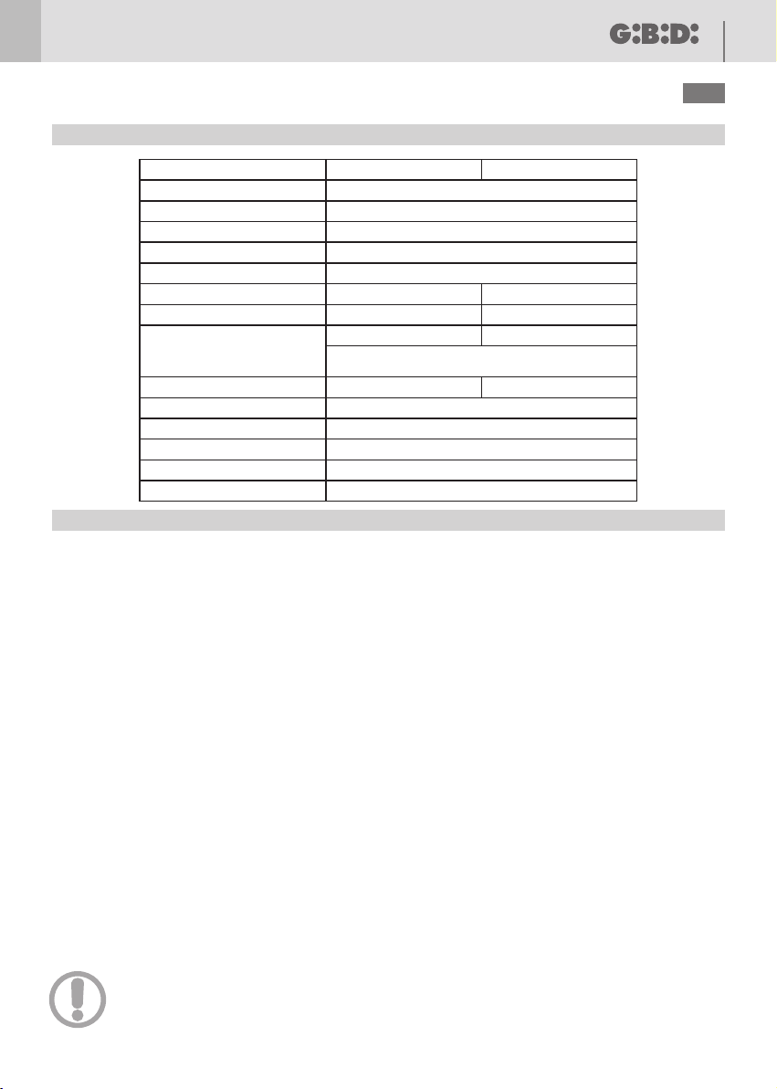
KUDA 150
24 Vdc
100 W (~1000 N)
4 A (~1000 N) MAX
360 mm
24 Vdc 2600 rpm
1000 N
-20°C + 60°C
IP 44
If fitted on blind/flush panel doors
it is mandatory to use an electric lock
Integrated into the motor
intensive
20 mm/s
KUDA 200
1500 N
2 m 2.5 m
400 mm
150 Kg 200 Kg
Electric system setup
Set up the electric system as shown in fig.1 referring to the electric system regulations and other national regulations
in force. Keep the mains power connections clearly separated from the service connections (photocells, sensitive
frames, control devices, etc.).
The main components are:
1- Antenna; screened coaxial cable
2- Electronic control unit container
3- Electric lock; 1 mm² 2-core (2x1) cable
4- Key selector; 0,5 mm² 3-core (3x0,5) cable
5- 24Vdc operators:
- 1,5 mm² 2-core (2x1,5) cable power supply WHITE = + YELLOW = -
for a cable length of 6 m max., over it’s necessary increase the cable section.
-0,5mm² 3-core (3x0,5) encoder cable.
6- Omnipolar magnetothermal and differential switch with minimum contact opening of 3 mm
220-230V/50-60Hz control unit power line: min. 1,5 mm² 3-core cable (3x1,5)
(adhere to the regulations in force)
7- 24V flashing light; 0,75 mm² 2-core (2x0,75) cable
8- Connector blocks
9- Photocell transmitter; 0,5 mm² 2-core (2x0,5) cable
10- Photocell receiver; 0,5 mm² 4-core (4x0,5) cable
A- Opening mechanical end-stop.
B- Closing mechanical end-stop.
ELECTRICAL EQUIPMENT
Supply voltage
Power absorbed
Current absorbed
Electric motor
Useful travel
Max thrust/traction force
Operating temperature
Frequency of use (%)
Degree of protection
Maximum leaf length
Linear velocity
Operator
Type Irreversible electromechanical with worm screw
TECHNICAL DATA
Maximum leaf weight
CAUTION: It is important that an omnipolar magnetothermal and differential switch with a
minimum contact opening of 3 mm be fitted upstream of the control unit.

KUDA
12
UK
Check that the gate structure is in conformity with the regulations in force and that the gate movement is linear
without friction.
Preliminary checks:
• Check that the gate structure is sufficiently robust.
• In any event, the actuator must push the leaf at a reinforced point.
• Manually check that the leafs move without force along their entire travel.
• Check that the gate opening and closing end-stops A-B fig.1 have been installed.
• If the gate is not a new installation, check the state of wear of all the components, and repair or replace the
defective or worn parts.
The reliability and safety of the automated device is directly dependent on the condition of the gate structure.
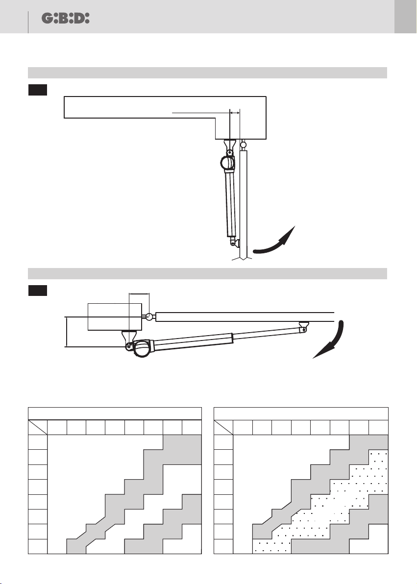
Refer to 6 for possible installation dimensions.
The difference between A and B must not exceed 50 mm; greater differences cause irregular gate movement
(the traction/thrust force and the movement speed vary during the manoeuvre).
fig.
PRELIMINARY WARNINGS
INSTALLATION DIMENSIONS
Preliminary checks:
For proper functioning of the automated device, the existing or new gate structure must meet the following
requirements:
The individual leafs must have a maximum length of 2 metres (KUDA 150) or 2,5 meters (KUDA 200)
The leaf structure must be robust and rigid
The leafs must move smoothly and uniformly without irregular friction along their entire travel
The existing hinges must be in a good condition
The mechanical end-stops A-B fig.1 must be fitted
fig. fig.
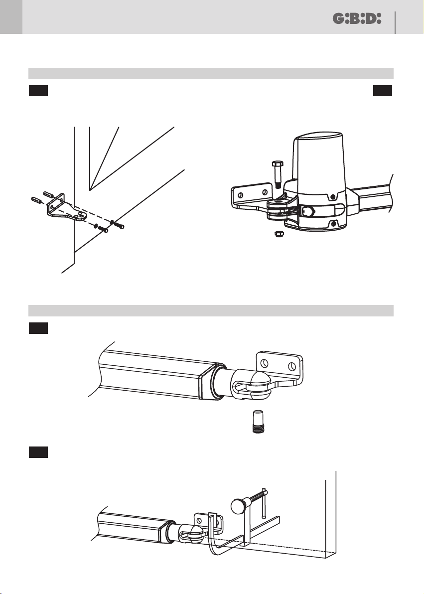
4 - Fasten the rear bracket to the pillar fig.7a .
5 - Fit the operator on the rear bracket using the pin provided fig.7b .
6 - Fasten the front bracket on the operator fig.8a .
7- Unlock the operator (see unlocking device), pull out the operator rod fully then push it inside for 20 mm.
8 - Move the leaf to closed position against the mechanical end-stop B fig.1.
Installing the operators
1 - Find the most suitable point where to fasten the front bracket of the operator and mark it.
2 - Using a spirit level mark the point on the pillar where to fasten the rear bracket .
3 - Identify the point where to fasten the rear bracket in relation to the dimensions A-B 6 and in relation to 3-4-5.
CAUTION: Where there are big pillars or walls, a niche must be made so that the dimensions A and B are
respected.
OPERATOR INSTALLATION

13
UK
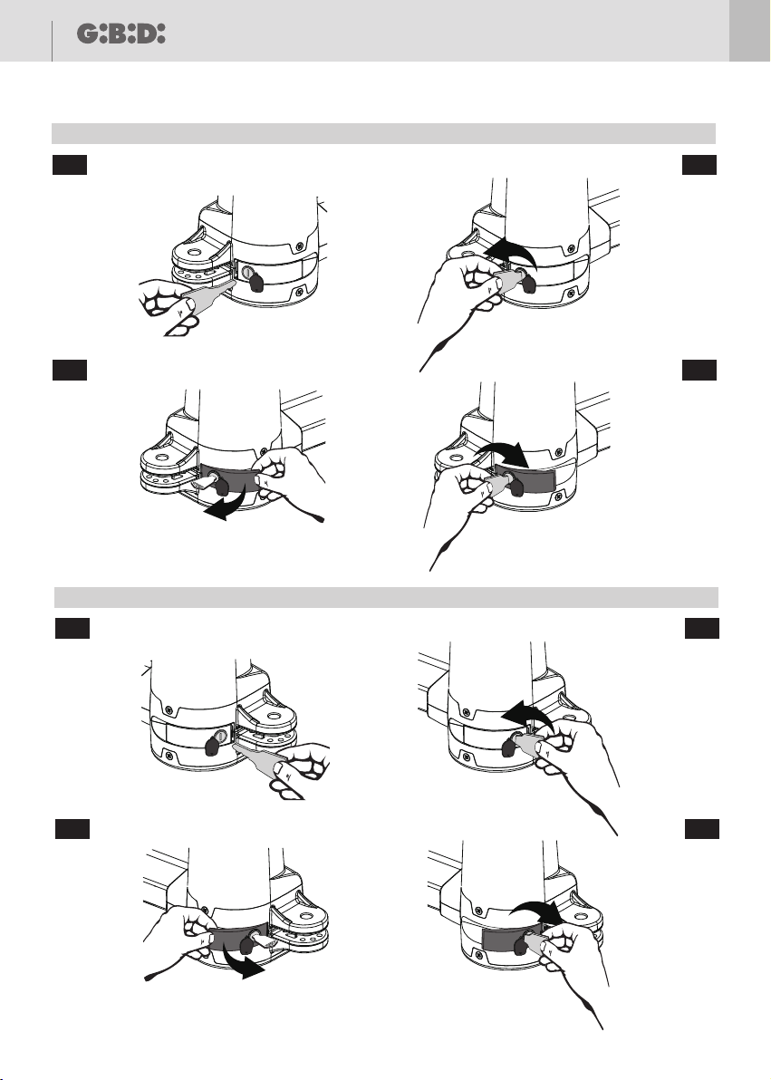
If the gate needs to be operated manually because of a power failure or operator malfunctioning:
Remove the rubber plug fig.9a-9e .
Insert the release key to the release slot fig. 9a-9e .
Turn the release key as shown in fig.9b-9f .
Pull out the release bar and keep it pulled out fig.9c-9g .
Turn the release key to its original position to fix the release bar fig.9d-9h .
Move the gate manually only in the event of a power failure.
UNLOCKING DEVICE
If you need to install an electric lock, refer to figures 11 and 12 .
1) ELECTRIC LOCK
2) ELECTRIC LOCK FASTENING PLATE
3) BUSHING
4) END-STOP FOR BUSHING
5) SPRING LATCH
6) THROUGH CYLINDER (ON REQUEST)
7) GATE
fig. fig.
INSTALLING THE ELECTRIC LOCK
Power the system and run a complete opening and closing cycle checking that:
• The safety devices function properly;
• The gate moves smoothly;
• Good hold of the fastening brackets;
• That the power cable moves freely;
• The gate assembly conforms to EN 12453 and EN 12445;
• For further details and information on the reference standards, visit our site: www.gibidi.com
FINAL CHECKS
9 - Fix the front bracket to the leaf with a clamp fig.8b .
10- Use a spirit level to check that the operator is perfectly level.
11 - Remove the operator from the front and rear bracket .
12 - Fasten the front bracket .
13- Unlock the operator (see unlocking device).
14 - Fit the operator on the brackets.
15 - Manually open and close the gate to its full opening and closing travel. The gate must move smoothly without
friction and the lead nut must not reach the mechanical end-stop during opening or closing. If otherwise, adjust
the bracket positions.
It is recommended to leave at least 40-50 mm of cable free.
OPERATOR INSTALLATION

KUDA
14
UK
Periodically check the gate structure, in particular:
- Check functioning of the hinges;
- Check that the leafs are correctly balanced. Excessive inclination of the leafs will result in faster wear of the
operator fastening brackets. Do the test by unlocking the operator and checking that the leafs do not move on their
own;
- Check good functioning of the safety devices;
- Unlock the operator and check that there are no points of friction along the entire travel;
- Check that there is no dirt or debris on the worm screw, and if so, clean and then lubricate the worm screw with
lubricating grease.
- Periodically check proper adjustment of the operator thrust force and the efficiency of the unlocking device for
manual operation (see the relative paragraph).
- The safety devices installed on the system must be checked every six months.
For any unresolved malfunction, cut the power to the system and call in a qualified technician (installer). In the
period when the gate is out of service, activate the manual unlocking device to allow manual opening and
MAINTENANCE
MALFUNCTIONING

KUDA 15
UK
CE Declaration of conformity
The manufacturer:
GI.BI.DI.
Via Abetone Brennero, 177/B,
46025 Poggio Rusco (MN) ITALY
Declares that the products:
ELECTROMECHANICAL GEARMOTOR KUDA 150-200
Are in conformity with the following CEE Directives:
•
EMC Directive 2004/108/CE and subsequent amendments;
and that the following harmonised standards have been applied:
•
•
Date 26/05/14
S.r.l.
Directive and subsequent amendments;LVD 2006/95/CE
•
EN60335-1,
EN61000-6-1, EN61000-6-3
Moreover declares that the product must not be used until the machine in which it has
been incorporated has not been declared in accordance with 2006/42/CE Directive.
The legal Representative
Michele Prandi

KUDA
KUDA 150 - (15000/DX-15000/SX) Operatore elettromeccanico lineare
DISEGNI E SCHEMI
Electromechanical linear operator
DRAWINGS AND DIAGRAMS
I UK
KUDA 200 - (22000/DX-22000/SX)

KUDA
2
991
IMPIANTO TIPO / TYPICAL INSTALLATION
1
2
3
4
5b
5a
6
7
8
8
10
10
9
9
A
A
B
5a 5b
LEFT OPERATOR-MOTOR 2
OPERATORE SINISTRO-MOTORE 2
RIGHT OPERATOR-MOTOR 1
OPERATORE DESTRO-MOTORE 1
B
922
DIMENSIONI OPERATORE / OPERATOR DIMENSIONS
98mm
46mm
93mm
400mm
799mm
29mm
KUDA 200
170mm
98mm
170mm
93mm
640mm
360mm
46mm
674mm
KUDA 150
29mm
765mm

KUDA 3
48
35
15
94
82
20
50
17
Ø9
17mm
15mm
993
STAFFE / BRACKETS
Ø9
991
APERTURA VERSO L’INTERNO / INWARD OPENING
994
Min
150mm
KUDA 150 MAX 120mm
KUDA 200 MAX 150mm
CHIUSURA / CLOSING
KUDA
4
991
APERTURA VERSO L’ESTERNO / OUTWARD OPENING
995
Min 70mm
APERTURA / OPENING
991
QUOTE INSTALLATIVE / INSTALLATION DIMENSIONS
996B
A
β°
120 130 140 150 160 170 180 190
120
130
140
150
160
170
180
190
B
A
β>120°
β=110°-120°
β=100°-110°
β<90°
β=90°-100°
210
β<90°
β=90°-100°
β=110°-120°
β>120°
β=100°-110°
140 150 160 170 180 190 200
140
150
160
170
180
190
200
210
B
A
KUDA150 KUDA200
KUDA 5
991
STAFFA POSTERIORE / REAR BRACKET
997a
991
STAFFA ANTERIORE / FRONT BRACKET
998a
991997a 991997a991997b
991998b
KUDA
6
991
MANOVRA DI SBLOCCO OPERATORE SINISTRO / LEFT MOTOR UNLOCK MANEUVER
999a 991999b
991999c 991999d
991
MANOVRA DI SBLOCCO OPERATORE DESTRO / RIGHT MOTOR UNLOCK MANEUVER
999e 991999f
991999g 991999h

KUDA 7
6
5
3
4
7
2
1
3
4
5
6
4
3
5
1
2
7
991
COLLEGAMENTI ELETTRICI / ELECTRICAL CONNECTIONS
9910
.
991
COLLEGAMENTO ELETTROSERRATURA / ELECTRIC LOCK INSTALLATION
9911 9919912
12 3 4 5 8
6
7
J4
9 10 11 12 13 16
14
15
J5 Motore 1 / Motor 1
GND
S1
5V
M1-
M1+
12 3 4 5 8
6
7
J4
9 10 11 12 13 16
14
15
J5
Motore 2 / Motor 2
GND
S2
5V
M2-
M2+

I UK
Apparecchiatura elettronica
ISTRUZIONI PER L’INSTALLAZIONE
Electronic control unit
INSTRUCTIONS FOR INSTALLATIONS
PC200 - (AS06050)
PC200

PC200
Red warning LEDs for N.C. contacts and for programming.
Buttons on the circuit board for programming and learning the radio controls.
Automatic run time learning with simplified procedure.
Onboard radio receiver that can store up to 200 radio controls.
Control of the radio transmitter channels via jumpers.
Deceleration during opening and closing.
Deceleration speed adjustable via DIP switch.
Stop and motion inversion after intervention of the safety devices.
Anti-crushing function both at normal speed and in deceleration.
Amperometric reading of motor absorption for the anti-crushing function adjustable via DIP switch.
Pedestrian operation with fixed opening of 5 seconds.
Two N.C. inputs programmable via DIP switch as photocell 1, photocell 2, N.C. frame or as opening device.
Two possible operating logics: step-by-step with stop or condominium selectable via DIP switch.
Gate phase shift time adjustable via DIP switch.
Programming of automatic closing and pause time via DIP switch.
Provision for use with buffer batteries.
Soft-Start and Soft-Stop to limit mechanical shock.
2 - TECHNICAL SPECIFICATIONS/FUNCTIONS
1 - TECHNICAL SPECIFICATIONS
SC230 / AS05710
230 VAC single-phase 50/60 Hz
2
24 Vdc
24 Vdc 10W max
Integrated
-20°C +60°C
ENCODER
12 Vdc 10W max
Electronic control unit for automation
of a double swing gate with 24VDC motors
Control unit
Power supply
No. of motors
Motor power supply
Flashlight
Radio receiver
Operating temperature
Run time
Accessory power supply
Type
WARNINGS: This product has been tested by GI.BI.DI. for full compliance with the requirements of the directives in force. GI.BI.DI. S.r.l. reserves the right to
change the technical data without prior notice in relation to product development.
DISPOSAL: GI.BI.DI. advises recycling the plastic components and to dispose of them at special authorised centres for electronic
components thus protecting the environment from polluting substances.
CAREFULLY READ THESE INSTRUCTIONS BEFORE PROCEEDING WITH INSTALLATION.
Thank you for choosing GIBIDI.
UK
11

PC200
991
INSTALLAZIONE APPARECCHIATURA / CONTROL BOARD INSTALLATION
991
2
PC200
991993991992
SW1SW2
ON
1 2 345 6 78
OFF
ON
1 2 345 6 78
OFF
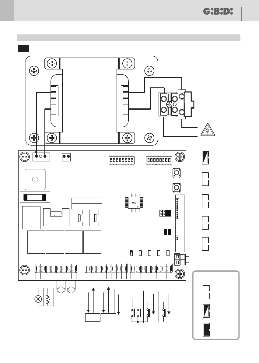
F1 20A
+
-
BAT 24V
24Vac
K5
K2 K3 K4K1
Q17
J2J1
DB1
R59
R60
Q11
Q14
PHASE
NEUTRAL
PED (NO)
START (NO)
GND
+12Vdc
PHOT2 (NC)
+12Vdc
PHOT1 (NC)
GND
GND
+12Vdc
GND
GND
+5Vdc
S2
17 18 19 20 21 2422 239 10 11 12 13 16
14
15
+5Vdc
S1
12 3 4 5 8
6
7
JP3
JP1 JP2
LIT
LIT
M2M1
S2
S3
SYS-learnRF-learn
ENCODER
M1
ENCODER
M2
LED1 LED2 LED3 LED4 LED5
ANTENNA
24Vdc
10W MAX
LED1
SYS-learn
LED2
START-PED
LED3
LED4
PHOT1
LED5
PHOT2
RF-learn
LED STATUS
ON
OFF
FLASHING
25 26
J4 J5 J3
J7
RX
SCHEMA ELETTRICO / ELECTRICAL CONNECTIONS
J10
+-+-
+-
+-
LAT
LAT
3
GND
1 2 1 2

PC200
3
COLLEGAMENTO ALIMENTAZIONE / POWER SUPPLY CONNECTION
PHASE
NEUTRAL
230Vac
PHASE
NEUTRAL
INTERRUTTORE DIFFERENZIALE
RESIDUAL-CURRENT DEVICE
INTERRUTTORE MAGNETOTERMICO
OVERCURRENT CIRCUIT BREAKER
J10
4
COLLEGAMENTO MOTORE / MOTOR CONNECTION
.
4
12 3 4 5 8
6
7
J4
9 10 11 12 13 16
14
15
J5
Motore 2 / Motor 2
GND
S2
5V
M2-
M2+
12 3 4 5 8
6
7
J4
9 10 11 12 13 16
14
15
J5 Motore 1 / Motor 1
GND
S1
5V
M1-
M1+
Other manuals for KUDA 150
1
This manual suits for next models
1
Table of contents
Other GBD Gate Opener manuals


Popular Gate Opener manuals by other brands


Casanoov
Casanoov RANGER B150 instruction manual

ATA
ATA NeoSlider NES-500 manual

GFA
GFA ELEKTROMAT KE 20.24-40,00 installation instructions

tau
tau EASY Use and maintenance manual

tau
tau ARM200 Series Use and maintenance manual

Motorline professional
Motorline professional LINCE400 User's and installer's manual