UK
22 TOP EVO 23
TOP EVO
UK
INTRODUCTION
INSTALLATION WARNINGS
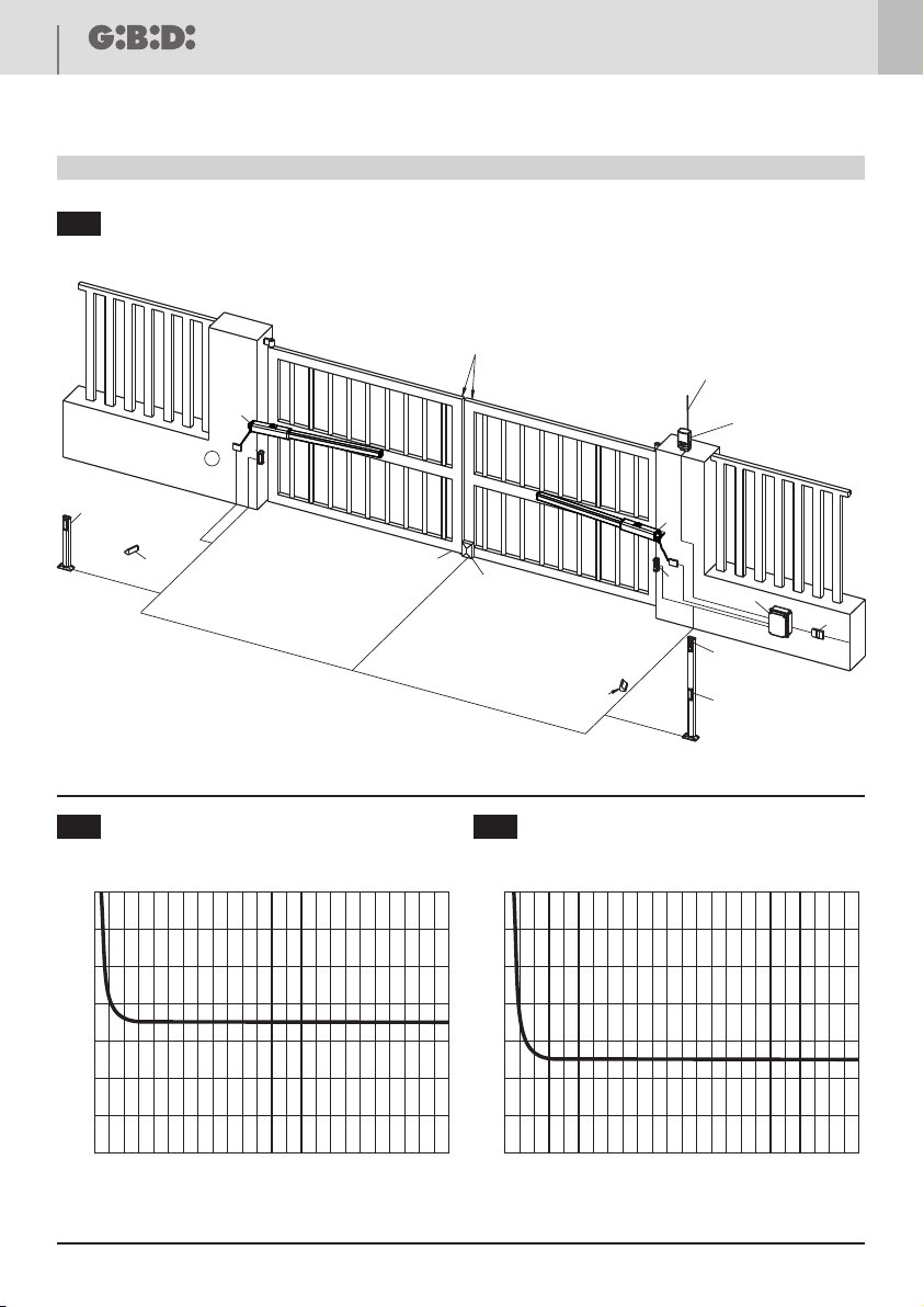
TOP EVO operator allows the automation of swinging gates.
The automation is composed by an operator with arm, that transmits the movement to the leaf, and by a built-in
hydraulic control unit.
TOP EVO operators are interchangeable with previous TOP versions, see chapter 8.
• Before proceeding with the installation, it is necessary to fit a magneto-thermal differential switch with a max.
capacity of 10A upstream of the system. The switch must guarantee an omnipolar separation of the contacts,
with an opening distance of at least 3mm.
• Keep all the materials contained in the packaging away from children since they pose a potential risk.
• The manufacturer declines all responsibility for improper functioning of the automated device, if the original
components and accessories suitable for the specific application are not used.
• After installation, always carefully check the proper functioning of the system and devices used.
• This instruction manual addresses professionals qualified to install “powered equipment” and therefore requires
a good technical knowledge and installation in compliance with the regulations in force.
• Maintenance must be carried out by qualified personnel.
• Before carrying out any cleaning or maintenance operation, disconnect the control unit from the main line.
• This product has been designed and constructed exclusively for the use indicated in this documentation. Any
other use may cause damage to the product and be a source of danger.
• Verify the end purpose of the product and take all the necessary safety precautions.
• The use of the products for purposes different from the intended use has not been tested by the manufacturer
and is therefore on full responsibility of the installer.
• Mark the automated device with visible warning plates.
• Warn the user that children or animals must not play or stand near the gate.
• Appropiately protect the dangerous points (for example, using a sensitive edge).
• Check the proper installation of the earthing system: connect all the metal parts of doors, gates, etc. and all the
system components to an earth terminal.
• Exclusively use original spare parts for any maintenance or repair operation.
• Do not modify any components of the automated device unless expressly authorised by GI.BI.DI.
• Use suitable cable clamps to ensure that the wiring is properly connected mechanically and such that an IP 65
protection degree is maintained.
WARNINGS:
This product has been tested by GI.BI.DI. for full compliance with the requirements of the directives in force.
GI.BI.DI. S.r.l. reserves the right to change the technical data without prior notice in relation to product
development.
READ CAREFULLY THESE INSTRUCTIONS BEFORE PROCEEDING WITH INSTALLATION.
Thank you for choosing GI.BI.DI.
DISPOSAL: GI.BI.DI. advises recycling the plastic components and to dispose of them at special
authorised centres for electronic components thus protecting the environment from polluting
substances.