gbo ULTRATHERM 908i User manual

gbo Medizintechnik AG 2004 Version 1.2
Short Wave Therapy Unit
ULTRATHERM 908i
Service Manual

ULTRATHERM 908i 2
gbo Medizintechnik AG 2004 Version 1.2
The gbo Medizintechnik AG has taken care in preparation of this service manual, but makes no
expressed or implied warranty of any kind and assume no responsibility for errors or omissions.
All rights reserved. No part of this service manual may be reproduced, in any form or by any
means (electronic, mechanical, or otherwise) without the prior written permission of the gbo
Medizintechnik AG.
gbo Medizintechnik AG 2004
gbo Medizintechnik AG
Kleiststr. 6
D-64668 Rimbach
Germany
Tel. 0 62 53 / 808-0
FAX 0 62 53 / 808-300

ULTRATHERM 908i 3
gbo Medizintechnik AG 2004 Version 1.2
Contents
CONTENTS 3
OVERVIEW 6
1. GENERAL INFORMATION 7
1.1. Purpose 7
1.2. Short User Manual 8
1.2.1. Operation Unit 8
1.2.2. Operation Direction 9
2. TECHNICAL DATA 10
3. ELECTRICAL AND FUNCTIONAL DESCRIPTIONS 11
3.1. Description of the subassemblies 11
3.1.1. Power supply - subassembly A100 11
3.1.2. Power generator - subassembly A200 11
3.1.3. Harmonic filter - subassembly A500 11
3.1.4. Output circuit - subassembly A300 12
3.1.5. Control computer - subassembly A400 12
3.2. Description of the Overall Wiring Diagram 14
4. TEST 15
4.1. Safety instructions 15
4.2. Testing devices and measuring instruments 15
4.3. Pretest 16
4.3.1. Check of earthing connections 16
4.3.2. Check of the fuse elements 16
4.4. Operation test 16
4.4.1. Stand by operation 16
4.4.2. Modes of operation 17
4.4.2.1. „MODE“ and „APPLICATOR“ keys 17
4.4.2.2. „+“ and „-“ keys, „MINUTES“ indicator 17
4.4.2.3. Power selector „INTENSITY“, indicators „WATTS“ and „TUNING“ 17
4.4.2.4. Emergency-off function 18
4.4.2.5. RESET key 18
4.5. Tuning 18
4.6. Check of the operating voltages and currents 19

ULTRATHERM 908i 4
gbo Medizintechnik AG 2004 Version 1.2
4.7. Check of generator frequency and pulse parameters 20
4.7.1. Generator frequency 20
4.7.2. Pulsed operation of „70 Hz“ 20
4.7.3. Pulsed operation of „350 Hz“ 20
4.8. Check of the power output 20
4.8.1. Coil applicator 20
4.8.2. Capacitor-field applicator 21
4.8.3. Auxiliary check of the power output 21
4.9. Check of the internal error recognition circuits 22
4.9.1. Temperature monitoring circuit 22
4.9.3. Generator voltage 22
4.10. Continuous operation 22
4.10.1. Preparation for continuous operation 22
4.10.2. Performance of the continuous operation 22
4.11. Final test 23
4.11.1. High-voltage test 23
4.11.2. Measurement of the leakage current of the casing 23
4.11.3. Earthing conductor test 23
4.11.4. Measurement of the mains current consumption 24
4.11.5. Check of the power values 24
4.11.6. Operation check 24
5. SERVICE INSTRUCTIONS 25
5.1. Function check of the power generator A200 25
5.1.1. Check of the supply voltages 25
5.1.2. Readiness for operation of the A200 subassembly 25
5.1.3. General information on the power loop 26
5.1.3.1. Level control 26
5.1.3.2. Amplification tract 26
5.1.3.3. Power and mismatching meter LFM 27
5.1.3.4. Adding amplifier 27
5.1.3.5. Subtracting amplifier 28
5.1.3.6. Multiplier (N202) 28
5.1.3.7. Setpoint/actual value comparator 28
5.1.3.8. Cable voltage monitoring circuit 29
5.1.3.9. Analogous OR interconnection 29
5.1.4. Operation of the power supply 29
5.1.5. Oscillator 30
5.1.6. Driver 30
5.1.7. RF circuits at the final stage output 30
5.1.8. Typical measurement values with a matched load (50 ohm) 30
5.2. Repair instructions for the control computer (A400) 31
5.2.1. Indication of the error conditions 31
5.2.2. Description of the control computer signals 32
5.3. Power supply (A100) 33
5.4. Output circuit (A300) 33
5.5. Harmonic filter (A500) 33

ULTRATHERM 908i 5
gbo Medizintechnik AG 2004 Version 1.2
6. DISASSEMBLY/ASSEMBLY FLOW CHART 34
7. ORDERING INFORMATION 35
8. PARTS LIST 37
9. WIRING DIAGRAMMS 38
CORRECTION SHEET 39

ULTRATHERM 908i 6
gbo Medizintechnik AG 2004 Version 1.2
Overview
Chapter 1 describes the basic purpose of the ULTRATHERM
908i.
Chapter 2 gives technical data of the unit.
Chapter 3 explains the functions of the subassemblys and the overall wiring diagramm.
Chapter 4 give some safety instructions during the service and describes the test of the whole
unit.
Chapter 5 includes the service instructions and informs about the trobleshooting.
Chapter 6 explains single steps to exchange a part.
Chapter 7 gives ordering information.
Chapter 8 gives a list of parts.
Chapter 9 contains the pictures and the wiring diagramms of the unit.

ULTRATHERM 908i 7
gbo Medizintechnik AG 2004 Version 1.2
1. General Information
1.1. Purpose
The ULTRATHERM 908i is a high performance short wave therapy unit for high frequencey
heat therapy that operates at the well proved frequency of 27,12 Mhz (wave lengh 11 m). It enables
the classical therapy in capacitor-field and electromagnetic coil fields in both the continuous and
the pulsed mode of oparartion and, therfore, it is suited for all heat therapy treatments in clinic as
well as practice.
The use of high frequency energy for the heat therapy has the advantage of larger penetration depth
in contrast to the conventional methods, such as hotpacks, baths, infrared light, heat pillows, and
even to the mirowave.
The heat endogenically generated by this therapy unit induces a whole range of physiological
processes which, for example, spasmodically influence the muscular system, tendons and other
connective tissue structures, increase the cell metabolism, rate of enzyme reaction and improve the
blood circulation in the area under treatment.
As the high frequency energy can be applied in short but high energy shocks (pulsed mode) the
penetration depth can be increased futher, particularly the positive effect on the blood circulation,
while the thermosensitive skin hardly feels the heat.
High frequency heat therapy can by applied in a wide field. It is particularly suited for all
rheumatic ailments of the joints and muscular system, inflammatory ailmants of respiratory
organs, kidnesy and urinary tracts and all ailments caused by blood circulation.
For acute conditions the pulsed mode of operation offers advantages.

ULTRATHERM 908i 8
gbo Medizintechnik AG 2004 Version 1.2
1.2. Short User Manual
1.2.1. Operation Unit
1Power switch with light indicator
2RESET key
3Key „Continuous mode of operation“ with LED.
4Key „Pulsed mode of operation“ 70 Hz/2 ms with LED
5Key „Pulsed mode of operation“ 350 Hz/0.4 ms with LED
6Key „Coil applicator“ MINODE ∅8 cm
7Key „Coil applicator“ MONODE ∅14 cm
14 16 15
1
2 3 4 5 6 7 8 11 10 9 12 13 17

ULTRATHERM 908i 9
gbo Medizintechnik AG 2004 Version 1.2
8Key „Coil applicator“ DIPLODE 18 x 39 cm
9Key „Capacitor-field applicator“ ∅4.2 cm and
„Capacitor-field applicator“, elastic 8 x 12 cm
10 Key „Capacitor-field applicator“ ∅8.5 cm
„Capacitor-field applicator“, elastic 12 x 18 cm
11 Key „Capacitor-field applicator“ ∅13 cm
„Capacitor-field applicator“, elastic 15 x 25 cm
12 Key „Decrease treatment time“
13 Key „Increase treatment time“
14 Display „treatment time“ in minutes
15 Display „Dosage“
16 Display „Coupling with patient“
17 Dosage knop
1.2.2. Operation Direction
•Connect the therapy unit to the mains socket outlet
•Connect the applicator(s) to the therapy unit
•Attach the applicator(s) to the patient
•Turn on the therapy unit with switch (1)
•Select the mode of operation, buttons (3), (4), (5)
•Select the mode of the applicator(s), buttens (6) to (11)
•Set the treatment time, button (12), (13)
•Set the dosage, knob (17)
•Electric power is applied to the output, the treatment timer starts operation
•After the chosen treatment time has elapsed, the therapy unit automatically turns off and emits
an intermittent acoustic signal for about 10 s. This signal is repeated every minute until the
dosage knob (17) is reset by turning to the left (counterclockwise).
•When an error is displayed (except for FE 0) press RESET button (2) and readjust if required.
•The entire therapy unit is switched off by actuating swich (1) again.
For more imformation please look in the User Manual of the ULTRATHERM 908i.

ULTRATHERM 908i 10
gbo Medizintechnik AG 2004 Version 1.2
2. Technical data
Mains Voltage
On request
230 V a.c. ±15% 50/60 Hz
115 V a.c. ±15 %; 50/60 Hz
Electric fuses (external) 10 A slow acting for 230 V
16 A slow acting for 115 V
Protective system Class I
Power consumption maximum
Stand-by oparation
about 700 VA
about 100 VA
Frequency 27,12 MHz ±0,6 %
RF output power at 50Ω
continuous mode
Pulsed mode
200 W
30 W
Power equivalent 400 W
Pulse parameters
Peak pulse power
Pulse repetition fequency
Pulse width
400 W
70 Hz/350 Hz
2 ms/0,4 ms
Dimensions 85 x 38 x 39 cm³ (HxWxD)
Weight 45 kg
Safety test DIN VDE 0750 Part 1
DIN VDE 0750 Part 204
DIN VDE 0871
MedGV - group 3

ULTRATHERM 908i 11
gbo Medizintechnik AG 2004 Version 1.2
3. Electrical and functional descriptions
3.1. Description of the subassemblies
3.1.1. Power supply - subassembly A100
The A100 subassembly is a mains-frequency clocked switching power supply generating the V1
(+5 V), V2 (+15 V) and V3 (-15 V) supply voltages. The outputs SK4 to SK6 are connected in
parallel to each other. Through plug connector SK7 (terminals 1 and 3) the mains power is fed in;
this connector is designed for 230 V as well as 115 V. The jumper „Link for 115 V operation“ is to
be plugged in accordance with the available mains voltage. The fine adjustment of the V2 supply
voltage is to be performed by means of control P1. When exchanging this subassembly it is to be
observed that the Y capacitors C16/C17 are not provided and that an electrically safe connection
between earthing conductor and base plate is to be ensured.
3.1.2. Power generator - subassembly A200
This module can be subdivided into three main sections. The first one includes the crystal-
controlled generation, amplification and filtration of the 27.12 Mhz high-frequency power. The
second one of this subassembly includes the measurement and control circuits which enable an
exact adjustment of the output power. And the third section contains the control circuit of the
operating voltage of the amplifier.
Any repair work of this subassembly shall only be performed by the manufacturer. That’s why,
this description is restricted mainly to the terminals. The supply power of the subassembly is fed
via the plug connectors X206 (+15 V), X209 (-15 V) and X210 (earth). Additional supply
terminals are X201 to X205 which are used for the regulation of the operating voltage of the
output amplifier. There importance as well as that of the terminals X207, X208, X211 to X213 is
described in detail in clause 3.2. The power is coupled out at the coaxial connector X222. This
A200 subassembly is delivered in the tested and tuned condition. Only the fine adjustment of the
output power is to be performed by means of R202.
3.1.3. Harmonic filter - subassembly A500
A harmonic filter, that additionally attenuates the RF interference spectrum in the frequency range
between 54 Mhz and 100 Mhz, is directly connected to the RF output of the power generator. It’s
adjustment is necessary to ensure being below the interference levels given by law. In case of
erroneous operation this subassembly has to be replaced in any case. Avoid any dismounting of the
air-core chokes L501/L502. The cover on this subassembly is absolutely necessary to maintain the
low RF interference values required by law.

ULTRATHERM 908i 12
gbo Medizintechnik AG 2004 Version 1.2
3.1.4. Output circuit - subassembly A300
The output circuit is provided to match the application part, which is connected to the balanced
output X004/X005, as exactly as possible to the generator. The matching is performed by means of
the adjustable capacitor C302 driven by stepping motor M301, which is a component of a serial
circuit in connection with the coils L302 and L303. The RF power is fed through connection
X301. The RF power flows via the capacitor chain C303 to C305 to the balance-to-unbalance
transformer L301/L302/L303 whose secondary windings are parts of the serial circuit mentioned
above.
The stepping motor is triggered by control computer A400. 4 additional diodes protect the
stepping motor (they are not drawn in the wiring diagramm).
All other parts, given in the layout, are not required.
3.1.5. Control computer - subassembly A400
Subassembly A400 is the central unit which realizes all signal and operation functions as well as
measurement and control operations. The micro-controller 87C196KB, which reduces the
computer hardware to a minimum and, thus, is a very service-friendly solution, is the basis of this
control computer.
The integrated circuit 87C196KB contains clock generator, CPU, program memory, A/D
converter, counter/timer and several different input and output ports. For clock generation (8 Mhz)
only the external components Q401, C406 and C406 are to be connected. After switchingon the
watch-dog circuit D401 generates a reset signal and initiates a defined start of the internal
program. But the generation of the reset signal is also possible by means of key S409. The supply
voltages +5 V, +15 V and -15 V are applied to the subassembly via X403. Mode of operation,
applicator type and treatment time are adjusted by means of the key matrix S401 to S408 and S410
to S412. They are triggered by the output ports P1.4 to P1.7 and evaluated by the input ports P2.1
to P2.3 which are loaded by the pull-up resistors R449 to R451. The output power is adjusted by
means of pulse generator D408, feeding the two direction-of-rotation dependent signals (2) and (4)
to the prosessor via NMI and P0.5. Processor output P2.5/PWM delivers a pulse-duration
modulated signal that is converted to a DC voltage by the two operational amplifier networks
N401A/N401B and used to control the power output of generator A200. The connection C402 to
D402 (P0.6) is used to monitor the D/A conversion. In the pulsed modes of operation the DC
voltage is keyed via processor output pin P4.7/AD15 and transistor T401. The generator control
voltage, the level of which is also monitored by processor (P0.6), applies at plug connector
X401.5. The bar indicator VD401 consists of ten LEDs and signals the degree of matching
between patient circuit and generator output. The individual LEDs VD402 to VD410 have the
following meaning:
VD402 signals the adjustment of the „DIPLODE“ applicator.
VD403 signals the adjustment of the Medium coil-field „MONODE“ applicator.
VD404 signals the adjustment of the Small coil-field „MINODE“ applicator.

ULTRATHERM 908i 13
gbo Medizintechnik AG 2004 Version 1.2
VD405 signals the adjustment of the „Large capacitor-field electrode“ applicator.
VD406 signals the adjustment of the „Medium capacitor-field electrode“ applicator.
VD407 signals the adjustment of the „Small capacitor-field electrode“ applicator.
VD408 signals the adjustment of the „350 Hz“ pulsed mode of operation.
VD409 signals the adjustment of the „70 Hz“ pulsed mode of operation.
VD410 signals the adjustment of the „continuous-wave“ (CW) mode of operation
The above information applies in multiplexed form at the processor output pins P3.0/AD0 to
P3.7/AD7 and is stored by the integrated circuits D404 to D406. This includes also the triggering
of the piezo-signal transmitter B401. Signal D406(Q5) and D406(Q6) is not used. The 7-segment
indicators VD411 to VD415 are also triggered in the multiplexed mode of operation. Data sources
are the processor output pins P4.0/AD8 to P4.3/AD11, the hexadecimal data of which are decoded
by integrated circuit D407. Amplified by T402 to T406 the multiplexed signals P2.0/TXT and
P1.0 to P1.3 are fed to the anodes of the indicator elements and show the following information:
VD411 shows the ten’s place of the minutes of treatment time.
VD412 shows the one’s place of the minutes of treatment time.
VD413 shows the hundred’s place of the unit’s output power.
VD414 shows the ten’s place of the unit’s output power.
VD415 shows the one’s place of the unit’s output power.
Integrated circuit D403 is used as driver circuit. In addition to the above signal it amplifies the
motor control signals (M301) which are generated at D402 (P2.6 and P2.7). Both signals are
directly amplified, inverted and transmitted to the plug connector X402 (pins 1 to 4). At each of
it’s outputs, D403 has a free-wheeling diode and the other-end connectors „D“ of which are
connected to the +15 V supply voltage.
The switch condition of the emergency-off switch connected at plug connector X403.6 is
evaluated by transistor T408 and terminal D402 (P2.4/T2RST) of the processor which signals this
information for further processing. An emergency-off actuation additionally releases a switching
operation of the transistors T409 and T407 where the collector of the last actuates the power relay
K001 via X403.5.
Micro-controller 87C196KB has eight analogous inputs (P0.0 to P0.7). The directional coupler
signals US+UDand US-UD, whose amounts are used for tuning the output circuit by means of
M301, are connected to P0.0 and P0.1. At X401.3 there applies a signal that is proportional to the

ULTRATHERM 908i 14
gbo Medizintechnik AG 2004 Version 1.2
output power. Via the resistor network R465/R466 this arrives at pin P0.2 of the processor. R465
is provided for tuning the output power of the unit.
This circuit realizes two additional monitoring functions. A thermistor (R003) is provided at the
heat sink of subassembly A200 for checking the temperature of this subassembly. It is connected
to X401.4. R439 is a component of a voltage divider whose output value is measured at pin P0.3.
The voltage across the power stage of subassembly A200 is monitored through the voltage divider
R440/R441 whose feeding point is connected to X401.8.
The diodes V401 to V405 and capacitors C407 to C425 meet protective and RF interference
protection functions.
3.2. Description of the Overall Wiring Diagram
The power supply of the ULTRATHERM 908i is realized by the mains transformer T001 and the
A100 subassembly that is connected with the 115 V or 230 V, 50 Hz/60 Hz, mains via mains input
A001, RF interference protection filter A002 and mains switch S001. The unit is adjusted to the
corresponding mains voltage by the manufacturer. The 45 V output voltage of T001 is required for
generating the supply voltage of the power stage of subassembly A200. The voltage is rectified by
bridge G001 the positive pole of which is connected to X205. In the other DC path there is
arranged thyristor V001 which is triggered by the operating voltage control circuit of subassembly
A200 and charges capacitor C001 in dependence on the generator output power. This is
synchronuously performed to the mains frequency, where the 26 V voltage of T001 between X205
and X203 is used. The regulated DC voltage between X205 and X201 is superimposed by a
serrated AC voltage of different amplitude and frequency.
C001 is discharged via the R002 resistor. The supply voltage of the control circuit applies between
X204 and X205.
The two DC voltages of +15 V (X206) and -15 V (X209), with their reference point X210, are
required for the analogous circuits of subassembly A200 and preamplifier. They are prepared in
the power supply module A100 (SK6.3 and SK6.4). The relay contact K001.1 which interrupts the
supply of the preamplifier under emergency-off condition is connected in series with the positive
signal path. The DC fan motor M001 is supplied with the negative voltage after a voltage
reduction by diode V002. Capacitors and Filters C002 to C019 are applied for certain measures of
the RF interference suppression.
A400 is fed via plug connector SK5 of subassembly A100. At SK4.1 the emergency-off switch is
connected to +5 V and the power relay K001 to -15 V (SK4.4). When the -15 V circuit is
interrupted, the contact opens and switches off the power of generator A200. The plug connectors
SK4 to SK6 are connected electrically in parallel and their common reference point „COM“ lies
on the casing potential.
The remaining part of the circuit was already described in the above description of the sub-
assembly. Finally, it is to be mentioned, that with any service work particularly care is to be taken
to the earthing connections given in the wiring diagram because they are decisive for maintaining
the low RF interference suppression level.

ULTRATHERM 908i 15
gbo Medizintechnik AG 2004 Version 1.2
4. Test
4.1. Safety instructions
Since the wiring, transformers, and switching assemblies, contained in this unit, are connected to
line voltages, the measurement and setting procedures, required for troubleshooting and
adjustment, must be performed with the utmost care.
Do not touch any connected measuring instruments or metal parts of the load test object while the
unit is switched on. Risk of burns!
Persons who are in the area surrounding the cables or applicators working, have to deposit all
metal objects such as watches, jewelry, keys, metal-rimmed eyeglasses, hearing aids, electronic
equipment, etc.
4.2. Testing devices and measuring instruments
•High-voltage measuring instrument (6 kV)
•High-voltage testing equipment
•Leakage current measuring device
•Earthing-conductor testing device (20 A)
•Insulation resistance measuring instrument
•Test aerial
•Power meter
•Probe
•Precision resistor 50 Ω(cf. Spare parts list)
•Line-voltage regulator (230 V)
•Adjustable isolating transformer
•Digital multimeter
•Moving-iron instrument (0.5 A,10 A)
•Oscilloscope (50 Mhz)
•Frequency meter (50 Mhz)
•Resistance phantom circuit
•Lamp phantom
•Thermometer (50 °C)
•Diverse measuring lines and coaxial transitions

ULTRATHERM 908i 16
gbo Medizintechnik AG 2004 Version 1.2
4.3. Pretest
•Remove the face of the unit.
•Remove the cover of the RF subassembly.
4.3.1. Check of earthing connections
•Visual inspection of the X001 connections to the unit’s rear wall and control desk.
•Visual inspection of screw connections at the base and RF subassemblies.
4.3.2. Check of the fuse elements
•F001/F002 (combined element A001) - according to the voltage version:
230 V version: SP 6.3 A, fast (ceramic pipe, dim. 5 mm x 20 mm)
115 V version: FST 6.26 A, slow (glass pipe, dim. 6.3 mm x 32 mm).
•F003 (mains transformer T001) - FST 50 mA, slow (glass pipe, dim. 5 mm x 20 mm).
•F1 (power supply A100) - FST 1.6 A, slow (glass pipe, dim. 6.3 mm x 32 mm).
4.4. Operation test
•Set mains switch S001 to position „0“.
•Connect the unit to the line-voltage regulator switched to the rated mains voltage.
•Mains-voltage indicator in S001 shall not be lit.
4.4.1. Stand by operation
•Switch on the unit by means of S001.
•Mains-voltage indicator in S001 shall be lit green (only with the 230 V version).
•Treatment time „MINUTES“ (VD411/412) indicates „0“.
•Power indicator „WATTS“ (VD413 to 415) indicates „0“.
•All other indicators are inactive.

ULTRATHERM 908i 17
gbo Medizintechnik AG 2004 Version 1.2
4.4.2. Modes of operation
4.4.2.1. „MODE“ and „APPLICATOR“ keys
•Pressing one of the 9 keys (S402 to 404, 406 to 408, 410 to 412) activates the assigned LED.
4.4.2.2. „+“ and „-“ keys, „MINUTES“ indicator
•A short actuation of the „+“ key (S405) increments the treatment time indicator „MINUTES“
by 1 (end value 30).
•Continuous actuation of the „+“ key increases the indicated time in steps of 5 digits (e. g. 5, 10,
15, etc. - end value 30).
•The actuation of the „-“ key (S401) has the similar effect but the time indicated is reset (end
value 0).
•Simultaneous actuation of both keys results in the indication of „0“
4.4.2.3. Power selector „INTENSITY“, indicators „WATTS“ and „TUNING“
•Separate the coaxial plug connection X222 and connect the generator output to the test aerial or
50 Ωprecision resistor, respectively.
•Check the indication of the power ranges:
3 W to 30 W in 3 W steps
30 W to 80 W in 5 W steps
80 W to 200 W in 10 W steps
as well as the power range limits in dependence on the mode of operation and the applicator
selected in the following way.
•Select „CW“ mode, „DIPLODE“ applicator and treatment time (> 0);
•Turn the power selector (D408) by one click-stop detent to the right side;
•„A“ must appear on the „MINUTES“ indicator for Tuning;
•After switching over the indicator to treatment time the power of „9 W“ must be displayed, and
all LEDs of the bar indicator (VD401) are activated;
•Check the power ranges by additional incrementing the power selector to the right;
•Then set the power to „0“ by turning the power selector to the left side;
•Repeat this prosedure in the CW mode of operation for all applicators where the initial values
after the tuning operation (9 W each) as well as the end values are to be checked:
coil-field electrode, small 30 W
coil-field electrode, medium 90 W
capacitor-field electrode, small 21 W

ULTRATHERM 908i 18
gbo Medizintechnik AG 2004 Version 1.2
capacitor-field electrode, medium 80 W
capacitor-field electrode, larg 200 W
•Subsequently check the limit values of the power ranges in the pulsed modes (initial values 3 W
each), the end values are 30 W for all applicators except the small capacitor-field electrode with
21 W.
4.4.2.4. Emergency-off function
•Set the output power to any value > 0.
•Wait for the duration of tuning process.
•Actuate the emergency-off switch.
•A continuous acoustic signal must sound and all optical indications must be exstinguished.
•Relay K001 must be released.
•Then turn the power selector to the left.
•The acoustic signal terminates and the unit changes to the stand by mode.
•Relay K001 must be active.
4.4.2.5. RESET key
•Adjust any treatment time value.
•Press RESET key (S409).
•After this, the unit must be in the stand by mode.
4.5. Tuning
•Set the unit to the stand by mode.
•Engage the coaxial plug connection X222.
•Connect the test aerial to the unit output X004/X005.
(By way of substitution, the output power can be determined by means of the precision resistor
of 50 Ωand a multimeter. In such a case the following three steps can be neglected).
Calibration of the thermal probe with the power meter.
•Set the following parameters on the power meter:
„dB REL“ = 39.70 dB,
„LINEARITY FACTOR“ according to the value on the probe label,
„CAL FACTOR“ = 1,
„RANGE“ = 0,
„AVERAGE“ = 7,
„DUTY CYCLE“ = 100 %.
•Connect the power meter to the (-40)-dB output of the test aerial.
ULTRATHERM 908i 19
gbo Medizintechnik AG 2004 Version 1.2
•Connect the digital multimeter between the X206 and X210 terminals.
•Adjust the operating voltage „+15 V“ to 15.00 V ..15.05 V by means of P1 (A100).
•Set the unit to be tested to the following values:
„CW“ mode of operation,
„DIPLODE“ applicator,
Treatment time „30“,
Power „9“.
•After the automatic tuning run adjust the output power to 9 W ±0.3 W by means of R465.
•Set the power at the unit to be tested to „150“.
•Adjust the output power to 150 W ±2 W by means of R202.
•Set the power selector to „0“.
4.6. Check of the operating voltages and currents
•Set the mains power supply to rated mains voltage (constant).
•The measurement of the mains current consumption is performed by means of the moving-iron
instrument.
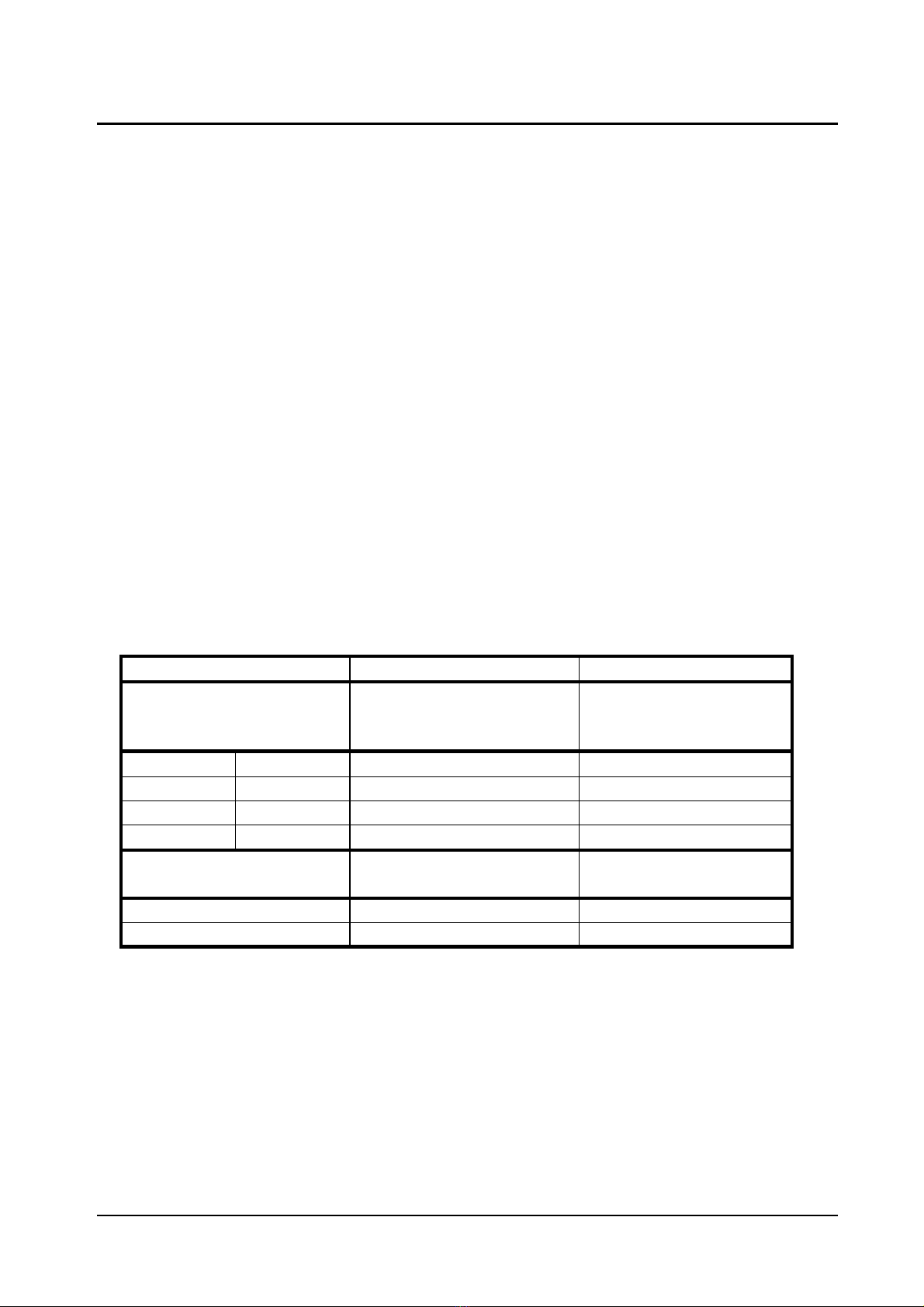
•With a load resistance of 50 Ωat X004/X005, the operating voltages and currents are to be
measured in the stand by mode (1) and for the output power of 200 W according to the
following table:
Test Setpoint (1) Setpoint (2)
Operating voltages
between:
(+) pole (-) pole
in V in V
SK5.1 earth +5 ±0.15 +5 ±0.15
SK5.3 earth +15 ±0.1 +15 ±0.22
SK5.4 earth -14.5 ±0.5 -5 ±0.22
X205 earth +12 ±2 +45 ±2
Mains current
consumption:in A in A
at 230 Va.c./50 Hz max. about 0.5 A max. about 3.0 A
at 115 Va.c./50 Hz max. about 1.0 A max. about 5.8 A

ULTRATHERM 908i 20
gbo Medizintechnik AG 2004 Version 1.2
4.7. Check of generator frequency and pulse parameters
4.7.1. Generator frequency
•Connect the test aerial to output X004 and X005.
•Connect the frequency meter to the (-40)-dB measurement output of the test aerial.
•Set the „DIPLODE“ applicator, „CW“ mode and treatment time.
•Adjust the power, wait for the tuning run.
•Determine the transmitter frequency (fsetpoint = 27.11 Mhz to 27.13 Mhz).
•Turn the power selector to „0“.
•By way of substitution and with the above adjustments, the generator frequency can be
measured with a capacitor of 1 pF/400 V connected in series to socket X004/X005 in the no-
load operation.
4.7.2. Pulsed operation of „70 Hz“
•Connect the oscilloscope to the (-40)-dB measurement output of the test aerial.
•Select the „70 Hz“ pulsed mode and the treatment time.
•Select the output power and wait for the tuning run.
•Measure the pulse duration (tp/setpoint = 1.8 ms to 2.2 ms) and frequency (fsetpoint = 65 Hz to 75
Hz) by means of the oscilloscope.
•Set the power selector to „0“.
•The pulse duration can also be determined by means of the oscilloscope at the precision resistor
of 50 Ω.
4.7.3. Pulsed operation of „350 Hz“
•Select the „350 Hz“ pulsed mode and proceed according to clause 4.7.2.
•Measure the pulse duration (tp/setpoint = 350 µs to 450 µs) and frequency (fsetpoint = 325 Hz to 375
Hz) by means of the oscillossope.
•Set the power selector to „0“.
4.8. Check of the power output
4.8.1. Coil applicator
•Connect the test aerial including the thermal power meter to X004/X005.
•Instead of test aerial and thermal power meter the precision resistor of 50 Ω, multimeter and
oscilloscope can be used. However, with the pulsed modes now the power can only be
Other manuals for ULTRATHERM 908i
1
Table of contents
Other gbo Medical Equipment manuals

gbo
gbo HiToP 191 User manual

gbo
gbo HiToP 184 User manual

gbo
gbo HiToP Metabol User manual

gbo
gbo NEOSERV 114 User manual

gbo
gbo DUODYNATOR 1049 User manual

gbo
gbo Stereodynator User manual

gbo
gbo SONOSTAT 135 User manual

gbo
gbo ULTRATHERM 908i User manual

gbo
gbo HiToP 191 User manual

gbo
gbo HiToP 1touch User manual
Popular Medical Equipment manuals by other brands

Idutex
Idutex Vpecker E4 Product introduction

Guldmann
Guldmann Evocare 553000 user manual

CYMEDICA Orthopedics
CYMEDICA Orthopedics e-vive NMES user manual

Dräger
Dräger Perseus A500 Instructions for use

Orliman
Orliman NEURO-CONEX 94304D INSTRUCTIONS FOR USE AND PRESERVATION

Beurer
Beurer IH 26 Kids Instructions for use


