gbo Stereodynator User manual
Interference Current Stimulation Device
Service Manual

2
gbo Medizintechnik AG 2009 Version 1.0
gbo Medizintechnik AG has taken care in the preparation of this manual, but does not assume any
liability, expressed or implied, of any kind nor does it assume any responsibility for errors or
omissions.
All rights reserved. No part of this manual may be reproduced, in any form or by any means
(electronic, mechanical, or otherwise) without the prior written permission of gbo Medizintechnik
AG.
© gbo Medizintechnik AG 2009
Version 1.0
Date of issue August 31, 2009
gbo Medizintechnik AG
Kleiststrasse 6
D-64668 Rimbach
Phone: + 49 6253/808-0
Telefax: + 49 6253/808-245
Internet: http://www.gbo-med.de

3
gbo Medizintechnik AG 2009 Version 1.0
Table of Contents
1INTRODUCTION ................................................................................................. 6
1.1 Intended use ..............................................................................................................6
1.2 gbo service concept ...................................................................................................7
1.3 Overview ....................................................................................................................7
1.4 Components...............................................................................................................7
1.4.1 Power supply................................................................................................................. 7
1.4.2 current amplifier ............................................................................................................ 8
1.4.3 Ultrasound amplifier ...................................................................................................... 8
1.4.4 Vacuum module ............................................................................................................ 9
1.4.5 Bus board...................................................................................................................... 9
1.4.6 Connector board ........................................................................................................... 9
1.4.7 Front plate with touch, display and backplane ............................................................... 9
2START OF OPERATION .................................................................................. 10
2.1 Transport and Assembly ..........................................................................................10
2.2 Connecting and Switch-On ......................................................................................10
2.2.1 Device Settings ........................................................................................................... 11
2.3 Short instruction .......................................................................................................12
2.4 Ultrasound Therapy Module.....................................................................................13
3MAINTENANCE ................................................................................................ 14
3.1 Safety Controls ........................................................................................................14
4TROUBLESHOUTING ...................................................................................... 15
4.1 Further errors ...........................................................................................................15
4.2 Error codes ..............................................................................................................15
5REMOVAL AND REPLACEMENT ................................................................... 21
5.1 Open the housing.....................................................................................................21
5.2 Removal of the current amplifier ..............................................................................24
5.2.1 Safety locking pin for the current amplifier boards ....................................................... 24
5.3 Removal of the bus board........................................................................................26
5.4 Removal of the power supply...................................................................................27
5.5 Removal of the ultrasound amplifier.........................................................................28
5.6 Dismount the vacuum module..................................................................................29
5.7 Mains input, fan and USB Connector......................................................................33
5.8 Front plate................................................................................................................33
5.9 Backplane, inverter and loud speakers ....................................................................34
5.10 Intensity knob and encoder board.........................................................................34
6EXPLANATION OF THE SIGNS USED ........................................................... 35
7TECHNICAL DATA........................................................................................... 36
7.1 Current types ...........................................................................................................37
8ACCESSORIES ................................................................................................ 40
9SPARE PARTS ................................................................................................. 41
10 BLOCK DIAGRAM......................................................................................... 42
11 INDEX............................................................................................................. 43
4
gbo Medizintechnik AG 2009 Version 1.0
Warnings and safety precautions
Warning!
Warnings which have to be observed by all means!
Caution!
Observe the instructions for use!
!!
Note!
Information that will facilitate your work.
5
gbo Medizintechnik AG 2009 Version 1.0
Warnings and Safety Precautions
Warning!
• For patients with implanted electronic device electrical stimulation treatment is
to be carried out only after having checked any risks.
• Jewellery and eyeglasses have to be taken off during the treatment.
• Turn off cellular phones and radiophones or place them in a distance of 3 m
from the device.
• Cardiac pacemakers are extremely vulnerable. Here the therapy should only be
carried out under continuous pulse and ECG control.
• If the patient and/or the patient cable is in the direct range of a high-frequency,
short-wave or micro-wave therapeutic device, a damage to the device or an in-
jury to the patient cannot be excluded. Please keep a clearance distance of 3 m.
• A simultaneous connection of the patient to a high-frequency surgery device
can lead to burns under the electrical stimulus electrodes.
• It is recommended not to exceed the current density of 2 mA/cm2on all
electrode surfaces.
• For current types with the threat of cauterization (all currents with galvanic
portion), the maximum recommended current density is 0.5 mA/cm2 electrode
surface. For galvanization the limit value is 0.2 mA/cm2and for iontophoresis
0.1 mA/cm2.
• Do not use disposable (self adhesive) electrodes with currents with galvanic
portion since there is the threat of cauterization!!
• The unit is not designed to be operated in places with the inherent risk of
explosions. If it is used in dangerous areas of anesthesia departments, the
possibility of an explosion cannot be excluded.
• In case of short circuit the lithium battery, the battery can explode. Only service
staff should change the battery.
• In case of any visible failure contact
gbo Medizintechnik AG or one of the service agencies authorized by gbo
Medizintechnik AG immediately.
Safety of service personnel
Warning!
• Take care that the mains cable is unplugged before any components are
removed or exchanged
• In case of service operation with the open unit keep care about high voltages
• The power supply may have the supply voltage (100 – 240V) on the metal parts
• The current amplifier boards produce the ±200 V by an internal switching
regulator
• The display backlight inverter generates high voltages, take care not to touch
contacts during normal operation

6
gbo Medizintechnik AG 2009 Version 1.0
1 Introduction
1.1 Intended use
The device with interference current named Stereodynator is a microprocessor controlled electrical
stimulus device for Electro Therapy. The wide range of usage qualifies this medical device for use
in physiotherapeutic departments of clinics as well as in modern well-equipped private medical
practices.
All accessories of the previous series can also be used with the new generation in the same manner.
A suction application aid for vacuum therapy as well as a module for ultrasound therapy with
continuous and impulse ultrasound waves are optionally available. The control elements for suction
application aid and ultrasound have already been integrated in the software and can be activated by
upgrading the device.
A stereodynamic interference current is generated through the superposition of three middle-
frequency currents flowing in different directions. The stimulating lower frequencies are generated
through interference of two phase shifted circuits in the area of superposition. The additional third
circuit generates, as opposed to classical interference methods, on one side a slow change in
intensity and on the other side a rhythmic shifting of the interference field. These dynamics of the
stimulation location and the intensity decrease the habituation effect and therefore improve the
therapeutic effect. The Stereodynator uses the three-dimensional interference method. The special
characteristics are as follows:
• Local stimulation effect.
• Multi-site stimulation effect.
• Intensity dynamics.
• Dynamic behaviour of stimulation site coupled with endogenous/exogenous stimulation shifting.
Programs improve the handling: The Stereodynator is equipped with several programs which
automatically set the treatment frequency and the treatment time.
The stimulating effect can alternatively be administrated endogenously or exogenously. During
endogenous application, the interference is generated through superposition of the electrical circuits
in the body. This allows an intense effect. During exogenous application, the interference is created
in the medical device. The stimulating effect takes place directly underneath the electrodes on the
body surface.
In addition to the three-circuit interference current, the Stereodynator offers a complete selection
of single circuit currents for all known therapeutic procedures.
The Stereodynator is particularly suitable for:
• Pain therapy with three-dimensional interference current.
• Muscle toning and muscle detoning.
• Galvanization and iontophoresis.
• Pelvic floor stimulation.
• Treatment of urinary and fecal incontinence.
• Treatment of paralyses with complete or partial muscular degeneration.
• Treatment of atrophies due to inactivity or weakened muscles after longer periods of inactivity.
• Electrical stimulation therapy without electrolytic side effects and only slight muscle fatigue.
• Treatment of pain, muscle spasms, functional diseases of the locomotor system, such as sports
injuries, peripheral circulatory disturbances, influencing of the vegetative system with

7
gbo Medizintechnik AG 2009 Version 1.0
diadynamic currents, ultrastimulation current, microstimulation current, TENS- and TENS Burst
currents, high-voltage currents and middle-frequency currents.
In medical diagnosis it is suitable for:
• Qualitative and quantitative determination of faradic excitability.
• Determination of the rheobase, chronaxy and accommodability.
• Recording of stimulus intensity/stimulus time characteristics (I/T curves) with defined,
measurable and reproducible rectangular and triangular pulses (exponential current).
• MF test according to Dr. Lange.
• Extensive non-invasive electro-diagnostics of peripheral paralyses.
• Neurodiagnostic examinations with galvano-palpations.
1.2 gbo service concept
Servicing gbo devices is based on a board replacement to ensure good quality and proper function
of the devices. As many components on the PCBs are SMD parts, which makes soldering a
complicated task, it is not recommended to change components on the boards. Even more, some
components require seperate adjustment procedures when exchanged, and also special calibrated
measurement tools.
This service manual is intended to help you learning about the structure of the device, and to guide
you through failure analysis in a defined way. Especially you will find out which component should
be replaced and how this will be done.
After exchanging components, it is necessary to execute the safety test (measurement of leakage
currents, check of protective earth connection).
1.3 Overview
The Stereodynator is a two channel unit for treatment with single channel currents. It can also be
used as an Interference unit with 2 or 3 channels. The interference with two channels is done by
four separate electrodes. The interference with 3 channels (Stereodynamic Interference or 3
dimensional Interference) is done by special electrodes. Two electrodes with 3 poles on each
electrodes are used for Stereodynamic interference.
Optionally a vacuum module can be integrated into the unit. This vacuum module allows the user to
perform a treatment with suction electrodes.
Optionally an Ultrasound module allows the user to perform an Ultrasound treatment or a
combination treatment with current. Therefore the ultrasound probe replaces one of the two
electrodes.
The Stereodynator is easy to use. All currents can be selected by a 15” display with touch screen.
Changes in the parameters for each current can easily be done. Own currents can be stored by own
names. A patient database allows the recording of treatment sessions. Previously performed
treatments can be shown in the Logbook and can be selected for the next therapy.
1.4 Components
1.4.1 Power supply
The power supply used is a switched power supply with a wide input from 100 – 240V and an
output voltage of 48V DC. The power supply is 60601-1 approved.

8
gbo Medizintechnik AG 2009 Version 1.0
1.4.2 current amplifier
This board handles the generation of the current signals. It includes a seperate microcontroller. The
software running on this microcontroller can be updated by the operating Software, so there is no
need to open the device and install the software manually to this processor. The CPU controls the
frequency and the amplitude of the current signal, which is amplified in the power amplifier. The
power amplifier is based upon two power Mosfet transistors. A relay separates the patient from the
current signal.
The detection of an open circuit is also included on the board. The patient current is measured and
transfered to the operating software. The communication between operating software and the
current amplifier is performed by serial interface. In case of three channel treatment the current
amplifiers can be synchronized.
The supply voltage of ±200V are generated on each current amplifier board. The ±15V are
generated out of the +5V supply which are generated separetely for each channel at the bus board.
Sinus Signals are generated by a DDS Chip, multiplied with the Intensity and amplified by the
power stage. All other signals are generated by the Microcontroller, multiplied and amplified by the
power stage.
The power amplifier boards are directly plugged to the bus board by two connectors. A maximum
of three boards can be connected to the bus board. The boards are kept by card holders and secured
with safety sticks. 3 current amplifier boards are installed in Stereodynator. They are directly
connected to the connector board by a cable harness.
A relay for combination therapy allows to switch the current signal to the ultrasound amplifier.
However, combination therapy is only possible at channel II. The combination therapy relay
switches the electrode contact of channel II to the metal surface of the ultrasound probe.
1.4.3 Ultrasound amplifier
This board handles the generation of the ultrasound signals. It includes a seperate microcontroller.
The software running on this microcontroller can be updated by the operating Software, so there is
no need to open the device and install the software manually to this processor. The CPU controls
the frequency and the amplitude of the ultrasound signal, which is amplified in two stages, a
preamplifier and a power amplifier. The power amplifier is based upon two power mosfet
transistors. A transformer insures the isolation of the patient.
A relay is used to switch between the two ultrasound outputs of this board. So only one of the ultrasound
outputs of the device will be active. It is possible to pass a stimulation current signal to the selected probe, so
that the electrical signal will appear at the surface of the ultrasound probe.
Another relay is used to switch an on-board filter circuit from 1 MHz to 3 MHz mode. The electrical signals
for the ultrasound probes are measured and used by the CPU for power regulation and coupling detection.
The power amplifier section may be switched off completely to protect it from overcurrent. A circuit senses
the current and reversibly switches the power amplifier stage’s power supply off completely.
The temperature of the heat-sinks directly fixed to the PCB is sensed by NTC sensors.
The US power amplifier generates 27V supply voltage from the 48V which comes from the power supply.
Also, -5V are generated as supply for the analog parts on board. The +5V supply is generated on the bus
board.
Communication is done by RS232 signals running to the bus board. This interface is also used for Software
updates.
The power amplifier board is connected by a 7 pole cable to the bus board.

9
gbo Medizintechnik AG 2009 Version 1.0
The ultrasound probe’s connectors are connected to the power amplifier board. Each connector is connected
by a cable transmitting the ultrasound signal and an additional cable for the control signals, such as the probe
recognition signals.
1.4.4 Vacuum module
The Stereodynator uses vacuum function by the Venturi principle. This means that the unit blows the air
outwards through the special Venturi Electrodes. The fortune of this system is that there will be no fluids
inside the unit. All fluids which are aspirated inside the electrodes are blown out together with the air flow.
The 24V DC pump aspirates the air through an input filter with sound absorber. There are two outputs,
Channel I and channel II. Both channels can be opened or closed by a valve. So it is possible to use only
channel I, only channel II or both channels.
1.4.5 Bus board
The bus board is used to distribute several functions of the unit. It is connected to the backplane by USB bus.
On the Bus board the USB bus is distributed. The Bus board includes 2 USB hubs. All 3 current amplifiers
are connected by RS 232. This signals are generated by USB to serial converters. The current amplifiers are
directly connected to the bus board. The separated 5V for each of the current amplifiers are generated
separately on the bus board. The external USB connection is also one of the USB hub ports.
The microcontroller on the Bus board is also connected to a USB port. This microcontroller is used for
several functions:
- Communication to the operating software
- Control of the vacuum module
- Control of the Power supply of the current amplifiers
- Generation of the control signals for the ultrasound amplifier
- Control of the temperature sensors on the bus board
- Control of the relays for combination therapy on the connector board
- Control of the relays for endogenous/exogenous on the the connector board
- Detection of all code inputs on the connector board
- Control of the fan speed
- Control of the intensity regulator
- Control of the lighting ring around the intensity regulator
1.4.6 Connector board
On the connector board all 4 sockets for the electrodes are located. The sockets are soldered directly
to the board. To find out which type of electrode is connected, several code pins are present at the
sockets for the electrodes. A small microcontroller detects the state of the code pins and transmits
this information to the microcontroller at the bus board, which in turn sends this information to the
operating software.
1.4.7 Front plate with touch, display and backplane
The front plate is the user interface part for the touch screen and the display and allows user input and output.
The display is a 15” colour display with a resolution of 1024 x 768 pixels. The corresponding resistive touch
screen detects the input operations.
The PCB backplane is the carrier board for the single board PC. On this board the connections to the display,
the touch screen, USB, backlight inverter and loudspeakers are realised. The operating system is Windows
CE.
10
gbo Medizintechnik AG 2009 Version 1.0
2 Start of Operation
2.1 Transport and Assembly
The Stereodynator is a portable unit. To place the unit, each flat surface is appropriate. Keep a wall
distance of at least 20 cm. The device should neither be placed in front of radiators nor should it be
covered by pillows or blankets while in operation. The lower side of the unit must be a plane area.
For maximum usability there is a special device cart available (see chapter 8, accessories) which
matches in design and function with the new Stereodynator. This device cart is perfect for the
placement of the unit and various accessories. With the device cart the Stereodynator is mobile and
always ready for use. For therapy it can easily be moved to the patient.
The Stereodynator corresponds to the regulations DIN/VDE 0750, EN 60601. It is a device of
protection class I. Within the scope of the Medical Device Directive (MDD) the current stimulation
device belongs to class IIa.
Warning!
The unit is not designed to be operated in places with the inherent risk of
explosions. If it is used in dangerous areas of anesthesia departments, the
possibility of an explosion cannot be excluded.
If the patient and/or the patient cable is directly exposed to a radiator of a medical
device for high frequency heat therapy, damage of the device or danger to the
patient cannot be excluded. As a rule, a clearance distance of 3 m is sufficient.
2.2 Connecting and Switch-On
The current stimulation device has been adjusted for the connection to a supply voltage of 100 to
240 V. It is not necessary to switch over the voltage – the device adjusts itself automatically
according the present voltage.
Independently from the adjusted supply voltage, the device is suitable for mains frequencies of 50
to 60 Hz.
Connect the Stereodynator with the mains cable to a socket with protective earth terminal. The
protective earth must be properly connected to the indoor installation.
The device is switched on by the main switch on the back of the device.
11
gbo Medizintechnik AG 2009 Version 1.0
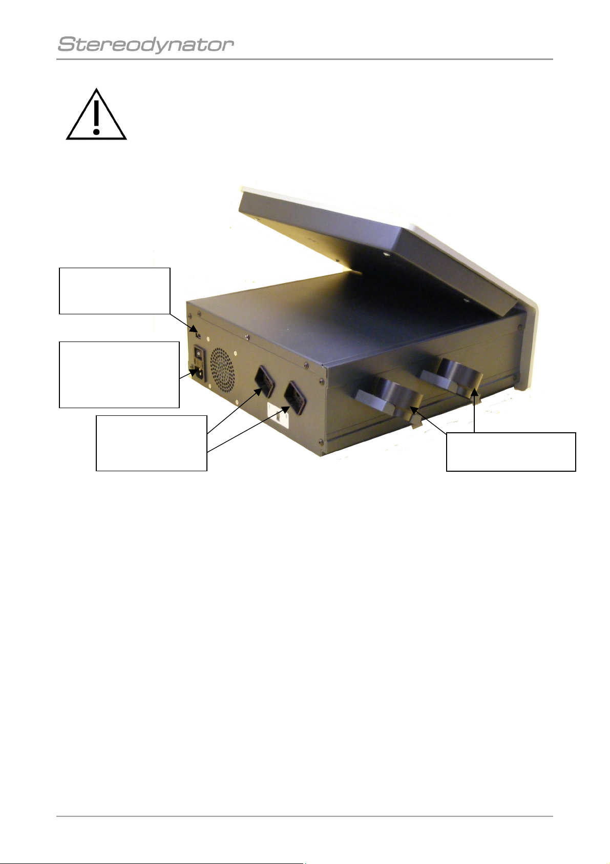
Warning!
It is only allowed to connect USB-Sticks for data backup and update!
Never connect a PC or another USB-device to this connector!
It is not allowed to use the two holder for Ultrasound probes as carrier handles!
Figure 1: Back and side view of the device
2.2.1 Device Settings
You reach the device settings menu by pressing the button „settings“ (see Fig. 2). In the device
settings menu all settings can be performed. With the direct help function you are able to retrieve all
information corresponding to the special menu item.
Main switch,
mains fuse
and connecting plug
for the mains cable
Connecting plug
for ultrasound
probe I + II
Holder for ultrasound
probe I + II
Connector for
USB-Stick
12
gbo Medizintechnik AG 2009 Version 1.0
2.3 Short instruction
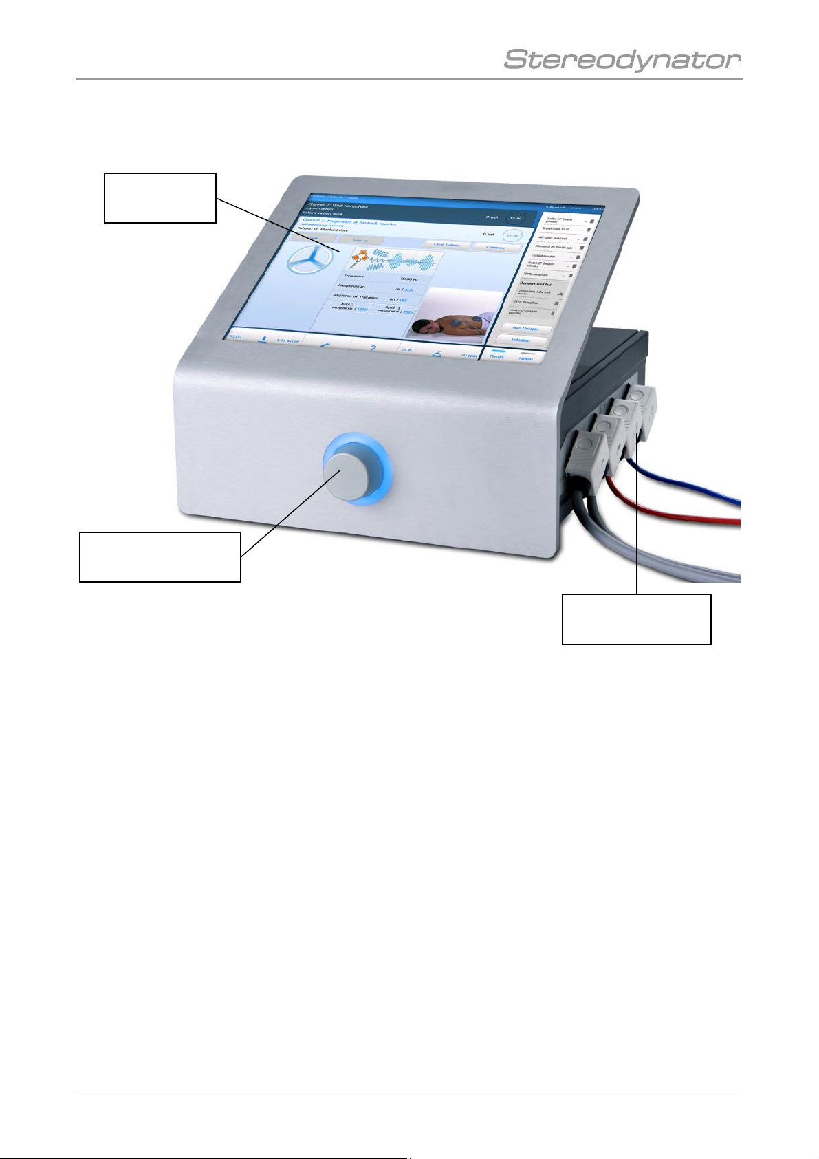
Figure 2: Front view
• Start the unit with the main switch on the back side
• Wait until the main screen appears (about 10-15 seconds)
• Press the button “More Therapies”
• Select a current from the list of currents
• Press the button accept to load the selected current
• Plug the corresponding electrodes to the socket at the unit
• Start vacuum if vacuum electrodes are connected
• Attach the electrodes to the patient (use the corresponding sponges or papers and make them
wet)
• Increase the intensity
• After therapy time is finished, the intensity will be decreased to 0
• A “Therapy End Signal” can be heard if the sound intensity is not set to 0
Touchscreen
display
Intensity regulator
(knob)
Connecting plugs
for patient cables

13
gbo Medizintechnik AG 2009 Version 1.0
2.4 Ultrasound Therapy Module
Depending on the device configuration, the ultrasound therapy module is either an optional or a
standard device (part no. 025-0-1000-U or 025-0-1000-UV). With the Ultrasound probe either
Ultrasound therapies as also combination therapies with Ultrasound and current can be done.
!! Note!
The ultrasound frequency can be changed to 1 or 3 MHz.
The frequency for pulsed mode is 100 Hz.
The selectable parameters are continuous or pulsed mode 1:1, 1:2, 1:5, 1:10 or
1:20.
The coupling status of the probe is shown by a LED on the probe's housing and
also as a graphical illustration on the display. The LED will be off in case of
insufficient coupling. The LED will be on in case of good contact.
As a standard setting the ultrasound power is shown in W/cm2on the display.
Warning!
Do not forget the contact gel!
The ultrasound probe has to be treated with care. External influences such as a
mechanical shock or impact can alter the characteristics of the ultrasound probe.
We recommend to carry out a visual examination at least once a year to check for
fissures that would allow liquids to soak in, as well as to make sure that the cables
and connectors are flawless.
Power for
5 cm2ultrasound probe 2.5 cm2ultrasound probe
1 MHz 0.5 to 15 W 0.1 to 3 W/cm20.1 to 7.5 W 0.1 to 3 W/cm2
3 MHz 0.1 to 7.5 W 0.1 to 1.5 W/cm20.1 to 2.5 W 0.1 to 1.5 W/cm2
Table 3: Setting options of the ultrasound power, increments are shown in bold.
!! Note!
Unless the ultrasound probe is coupled to the patient, no therapy time will pass.
When the probe is coupled again, the therapy time will resume. Hence, the
ultrasound probe can be removed during the treatment.
!! Note!
The Ultrasound probe can be exchanged. After switching on the unit or
respectively after plugging the Ultrasound probe each probe will be calibrated
individually.

14
gbo Medizintechnik AG 2009 Version 1.0
3 Maintenance
Functionality, reliability and safety characteristics of the Stereodynator are guaranteed only upon
handling the device in accordance with the operating instructions. Safety control, maintenance
work, repair work and modifications must only be carried out by the manufacturer or by service
agents authorized by him. In case of a failure, parts which influence the safety of the device must
only be replaced by original spare parts of the manufacturer. The electric installation must
correspond to the requirements in accordance with VDE/IEC. The device does not contain any
parts which need maintenance work done by the user.
3.1 Safety Controls
The device is subject to the provisions of the Medical Device Directive. The safety controls have to
be carried out on the basis of this directive. Thereby, the operator regulation has to be observed in
particular.
Irrespective of the legal rules or beyond the scope of the Medical Device Directive, it is
recommended to have the device checked by the manufacturer or by a service agency authorized by
him at 12- months intervals.
The check shall consist of at least the following criteria:
• Electrical safety check in accordance with the test plan of the manufacturer.
• Check of the device in respect of external integrity.
• Check of all display and operating elements in respect of damages.
• Check of all inscriptions in respect of legibility.
15
gbo Medizintechnik AG 2009 Version 1.0
4 Troubleshouting
Each problem that occurs during operation of the unit will be shown in a message window on top of
the display and also signalised by an acoustic tone. Most of the problems can be solved by the
instructions displayed.
In general:
1. The malfunction is shown on the display.
2. An acoustic signal is heard.
3. Follow the instructions on the display.
Suggestions:
• Turn off and turn on the unit.
• A full selftest of all device functions is performed and the unit is reinitialized. If the unit
does not come up to normal state, please call your local service.
4.1 Further errors
symptom
cause and action
Device cannot be switched on,
no display contents shown.
Please check the mains plug and sockets. If
necessary; contact your service agents or the
manufacturer.
No acoustic signal is heard.
(End of therapy…)
Please check the settings of the acoustic tones in
the menu. The volume must be greater than 0.
Please contact your service agent or the manufacturer if the problems cannot be solved by the
measures mentioned above.
Please note that the unit must be placed on a plane horizontal surface. The device should neither be
placed in front of radiators nor should it be covered with pillows or blankets while in operation. Do
not cover the ventilation slots on the bottom of the unit either.
4.2 Error codes
Error
code
Error message Probable cause Possible remedy
30033 Error during therapy: High temperature
at heat sink
Ultrasound probe defective
Power amplifier defective
Let the device cool down.
Check with another Ultrasound probe.
If the problem still exists change
ultrasound amplifier board.
30034 Error during therapy: High current
(Software)
Ultrasound probe defective Check with another Ultrasound probe.
30035 Error during therapy: High current
(Hardware)
Ultrasound probe defective Check with another Ultrasound probe.

16
gbo Medizintechnik AG 2009 Version 1.0
Error
code
Error message Probable cause Possible remedy
30036 Error during therapy: RS323 watchdog Cable connection Bus board to
Ultrasound power amplifier board
disconnected or broken
Ultrasound power amplifier board is
defective
Check cable connection Bus –
Ultrasound amplifier board.
Check if diagnose LED on the PCB
Ultrasound amplifier is flashing when
power on. If diagnose LED does not
flash, change Ultrasound power
amplifier board
30129 Error while calibrating the 1 MHz range
of channel 1: Parameter error
Ultrasound probe defective Check with another Ultrasound probe.
30130 Error while calibrating the 1 MHz range
of channel 1: No zero-crossing of Phi
Ultrasound probe defective Check with another Ultrasound probe.
30131 Error while calibrating the 1 MHz range
of channel 1
Ultrasound probe defective Check with another Ultrasound probe.
30134 Error while calibrating the 1 MHz range
of channel 1: Current too high
Ultrasound probe defective Check with another Ultrasound probe.
30135 Error while calibrating the 1 MHz range
of channel 1: Temperature too high
Ultrasound probe defective
Power amplifier defective
Let the device cool down.
Check with another Ultrasound probe.
If the problem still exists change
ultrasound amplifier board.
30137 Error while calibrating the 1 MHz range
of channel 1: Cannot find offset
Ultrasound probe defective Check with another Ultrasound probe.
30138 Error while calibrating the 1 MHz range
of channel 1
Ultrasound probe defective Check with another Ultrasound probe.
30162 Error while calibrating the 3 MHz range
of channel 1: Phi too small
Ultrasound probe defective Check with another Ultrasound probe.
30163 Error while calibrating the 3 MHz range
of channel 1
Ultrasound probe defective Check with another Ultrasound probe.
30164 Error while calibrating the 3 MHz range
of channel 1: Minimal Phi was not
reached (start frequency)
Ultrasound probe defective Check with another Ultrasound probe.
30165 Error while calibrating the 3 MHz range
of channel 1: Minimal Phi was not
reached end frequency)
Ultrasound probe defective Check with another Ultrasound probe.
30166 Error while calibrating the 3 MHz range
of channel 1: Current too high
Ultrasound probe defective Check with another Ultrasound probe.
30167 Error while calibrating the 3 MHz range
of channel 1: Temparature too high
Ultrasound probe defective
Power amplifier defective
Let the device cool down.
Check with another Ultrasound probe.
If the problem still exists change
ultrasound amplifier board.
30169 Error while calibrating the 3 MHz range
of channel 1: Cannot find offset
Ultrasound probe defective Check with another Ultrasound probe.
30170 Error while calibrating the 3 MHz range
of channel 1: No maximum found
Ultrasound probe defective Check with another Ultrasound probe.
30193 Error during the Sono Self Check: 27V
out of tolerance
Power amplifier defective Change ultrasound amplifier board.
30194 Error during the Sono Self Check: -5 V
out of tolerance
Power amplifier defective Change ultrasound amplifier board.
30199 Error during the Sono Self Check: ROM
checksum incorrect
Power amplifier defective Change ultrasound amplifier board.
30200 Error during the Sono Self Check: NTC
1 open
N
TC on Ultrasound amplifier board
disconnected or broken
Check connection of NTC
Measure resistance of NTC, the value is
6,8 kOhms at 25°C
30201 Error during the Sono Self Check: NTC
1 short
N
TC on Ultrasound amplifier board has
a short circuit or PCB Ultrasound
amplifier is defective
Check cable of NTC
If NTC is OK change Ultrasound
amplifier board
30202 Error during the Sono Self Check: NTC
2 open
N
TC on Ultrasound amplifier board
disconnected or broken
Check connection of NTC
Measure resistance of NTC, the value is
6,8 kOhms at 25°C
30203 Error during the Sono Self Check: NTC
2 short
N
TC on Ultrasound amplifier board has
a short circuit or PCB Ultrasound
amplifier is defective
Check cable of NTC
If NTC is OK change Ultrasound
amplifier board

17
gbo Medizintechnik AG 2009 Version 1.0
Error
code
Error message Probable cause Possible remedy
30225 Communication error Cable connection Bus board to
Ultrasound power amplifier board
disconnected or broken
Ultrasound power amplifier board is
defective
Check cable connection Bus –
Ultrasound amplifier board.
Check if diagnose LED on the PCB
Ultrasound amplifier is flashing when
power on. If diagnose LED does not
flash, change Ultrasound power
amplifier board
31129 Error while calibrating the 1 MHz range
of channel 2: Parameter error
Ultrasound probe defective Check with another Ultrasound probe.
31130 Error while calibrating the 1 MHz range
of channel 2: No zero-crossing of Phi
Ultrasound probe defective Check with another Ultrasound probe.
31131 Error while calibrating the 1 MHz range
of channel 2
Ultrasound probe defective Check with another Ultrasound probe.
31134 Error while calibrating the 1 MHz range
of channel 2: Current too high
Ultrasound probe defective Check with another Ultrasound probe.
31135 Error while calibrating the 1 MHz range
of channel 2: Temperature too high
Ultrasound probe defective
Power amplifier defective
Let the device cool down.
Check with another Ultrasound probe.
If the problem still exists change
ultrasound amplifier board.
31137 Error while calibrating the 1 MHz range
of channel 2: Cannot find offset
Ultrasound probe defective Check with another Ultrasound probe.
31138 Error while calibrating the 1 MHz range
of channel 2
Ultrasound probe defective Check with another Ultrasound probe.
31162 Error while calibrating the 3 MHz range
of channel 2: Phi too small
Ultrasound probe defective Check with another Ultrasound probe.
31163 Error while calibrating the 3 MHz range
of channel 2
Ultrasound probe defective Check with another Ultrasound probe.
31164 Error while calibrating the 3 MHz range
of channel 2: Minimal Phi was not
reached (start frequency)
Ultrasound probe defective Check with another Ultrasound probe.
31165 Error while calibrating the 3 MHz range
of channel 2: Minimal Phi was not
reached end frequency)
Ultrasound probe defective Check with another Ultrasound probe.
31166 Error while calibrating the 3 MHz range
of channel 2: Current too high
Ultrasound probe defective Check with another Ultrasound probe.
31167 Error while calibrating the 3 MHz range
of channel 2: Temparature too high
Ultrasound probe defective
Power amplifier defective
Let the device cool down.
Check with another Ultrasound probe.
If the problem still exists change
ultrasound amplifier board.
31169 Error while calibrating the 3 MHz range
of channel 2: Cannot find offset
Ultrasound probe defective Check with another Ultrasound probe.
31170 Error while calibrating the 3 MHz range
of channel 2: No maximum found
Ultrasound probe defective Check with another Ultrasound probe.
40000 Bus does not respond USB connection backplane to bus
disconnected or broken
Check the USB cable on both ends.
Check that the cable is no squeezed
40001 Error while opening the COM port Bus Microcontroller on the bus board is
defective
Change Bus board
40002 Error while configuring the COM Bus Microcontroller on the bus board is
defective
Change Bus board
40100 Undefined COM error Bus Microcontroller on the bus board is
defective
Change Bus board

18
gbo Medizintechnik AG 2009 Version 1.0
Error
code
Error message Probable cause Possible remedy
50001 A hardware error in channel 1 was
detected. Therefore the unit has to be
repaired for further use.
Please contact your service partner.
50100 PA1: Board does not respond
50101 PA1: Communication error
50102 PA1: CRC incorrect
50103 PA1: incorrect SOH
50104 PA1: incorrect EOH
50105 PA1: time out
50106 PA1: incorrect instruction
50107 PA1: time too short
50108 PA1: Instruction too short
50109 PA1: received CRC or frame number
incorrect
50110 PA1: received SOH incorrect
50111 PA1: received EOH incorrect
50112 PA1: Time-Out during reception
50200 Undefined COM error channel 1
50201 Error while opening the COM port
channel 1
50202 Error while configuring COM port
channel 1
51100 PA1: Board does not respond - during
therapy
51101 PA1: Communication error - during
therapy
51102 PA1: CRC incorrect - during therapy
51103 PA1: incorrect SOH - during therapy
51104 PA1: incorrect EOH - during therapy
51105 PA1: time out - during therapy
51106 PA1: incorrect instruction - during
therapy
51107 PA1: time too short - during therapy
51108 PA1: Instruction too short - during
therapy
51109 PA1: received CRC or framenumber
incorrect - during therapy
51110 PA1: received SOH incorrect - during
therapy
51111 PA1: received EOH incorrect - during
therapy
51112 PA1: Time-Out during reception - during
therapy
51200 Undefined COM error channel 1 - during
therapy
51201 Error while opening the COM port
channel 1 - during therapy
51202 Error while configuring COM port
channel 1 - during therapy
Current amplifier board 1 Check for the correct placement of the
board current amplifier 1.
If the board was properly mounted,
change the power amplifier board 1
19
gbo Medizintechnik AG 2009 Version 1.0
Error
code
Error message Probable cause Possible remedy
60001 A hardware error in channel 2 was
detected. Therefore the unit has to be
repaired for further use.
Please contact your service partner.
60002 PA2 was reset
60100 PA2: Board does not respond
60101 PA2: Communication error
60102 PA2: CRC incorrect
60103 PA2: incorrect SOH
60104 PA2: incorrect EOH
60105 PA2: time out
60106 PA2: incorrect instruction
60107 PA2: time too short
60108 PA2: Instruction too short
60109 PA2: received CRC or frame number
incorrect
60110 PA2: received SOH incorrect
60111 PA2: received EOH incorrect
60112 PA2: Time-Out during reception
60200 Undefined COM error channel 2
60201 Error while opening the COM port
channel 2
60202 Error while configuring COM port
channel 2
61100 PA2: Board does not respond - during
therapy
61101 PA2: Communication error - during
therapy
61102 PA2: CRC incorrect - during therapy
61103 PA2: incorrect SOH - during therapy
61104 PA2: incorrect EOH - during therapy
61105 PA2: time out - during therapy
61106 PA2: incorrect instruction - during
therapy
61107 PA2: time too short - during therapy
61108 PA2: Instruction too short - during
therapy
61109 PA2: received CRC or framenumber
incorrect - during therapy
61110 PA2: received SOH incorrect - during
therapy
61111 PA2: received EOH incorrect - during
therapy
61112 PA2: Time-Out during reception - during
therapy
61200 Undefined COM error channel 2 - during
therapy
61201 Error while opening the COM port
channel 2 - during therapy
61202 Error while configuring COM port
channel 2 - during therapy
Current amplifier board 2 Check for the correct placement of the
board current amplifier 2.
If the board was properly mounted,
change the power amplifier board 2

20
gbo Medizintechnik AG 2009 Version 1.0
Error
code
Error message Probable cause Possible remedy
70001 A hardware error in channel 3 was
detected. Therefore the unit has to be
repaired for futur use.\n\nPlease contact
your service partner.
70002 PA3 was reset
70100 PA3: Board does not respond
70101 PA3: Communication error
70102 PA3: CRC incorrect
70103 PA3: incorrect SOH
70104 PA3: incorrect EOH
70105 PA3: time out
70106 PA3: incorrect instruction
70107 PA3: time too short
70108 PA3: Instruction too short
70109 PA3: received CRC or framenumber
incorrect
70110 PA3: received SOH incorrect
70111 PA3: received EOH incorrect
70112 PA3: Time-Out during reception
70200 Undefined COM error channel 3
70201 Error while opening the COM port
channel 3
70202 Error while configuring COM port
channel 3
71100 PA3: Board does not respond - during
therapy
71101 PA3: Communication error - during
therapy
71102 PA3: CRC incorrect - during therapy
71103 PA3: incorrect SOH - during therapy
71104 PA3: incorrect EOH - during therapy
71105 PA3: time out - during therapy
71106 PA3: incorrect instruction - during
therapy
71107 PA3: time too short - during therapy
71108 PA3: Instruction too short - during
therapy
71109 PA3: received CRC or framenumber
incorrect - during therapy
71110 PA3: received SOH incorrect - during
therapy
71111 PA3: received EOH incorrect - during
therapy
71112 PA3: Time-Out during reception - during
therapy
71200 Undefined COM error channel 3 - during
therapy
71201 Error while opening the COM port
channel 3 - during therapy
71202 Error while configuring COM port
channel 3 - during therapy
Current amplifier board 3 Check for the correct placement of the
board current amplifier 3.
If the board was properly mounted,
change the power amplifier board 3
Table of contents
Other gbo Medical Equipment manuals

gbo
gbo HiToP 1touch User manual

gbo
gbo HiToP 191 User manual

gbo
gbo HiToP Metabol User manual

gbo
gbo DUODYNATOR 1049 User manual

gbo
gbo ULTRATHERM 908i User manual

gbo
gbo HiToP 191 User manual

gbo
gbo ULTRATHERM 908i User manual

gbo
gbo HiToP 184 User manual

gbo
gbo NEOSERV 114 User manual

gbo
gbo SONOSTAT 135 User manual


