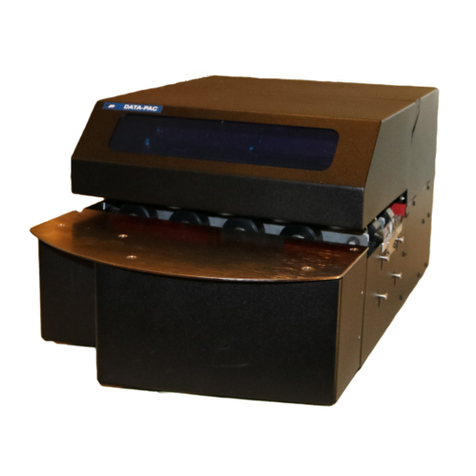
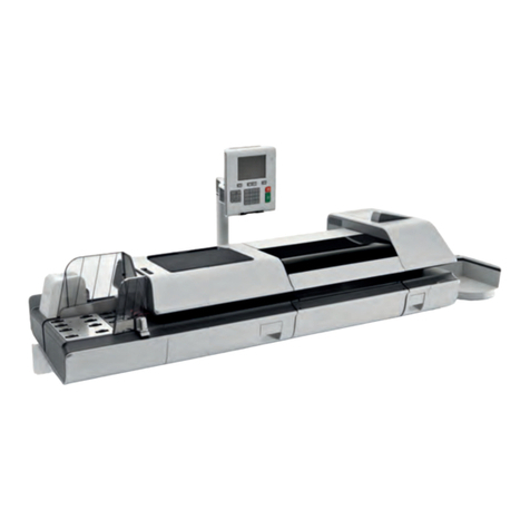
GBR Systems M-40 Operating manual

M-40 OPERATOR & SERVICE MANUAL ISSUE 05/01 COVER
071-27939-400(-) - 1 -
GO TO TABLE OF CONTENTS
M-40 Operator & Service Manual
ISSUE 05/01
071-27939-400(-)

M-40 OPERATOR & SERVICE MANUAL ISSUE 05/01 COVER
071-27939-400(-) - 2 -
NOTICE
While every care has been taken in the preparation of this manual, no liability will be accepted by GBR Systems Corporation arising out of any inaccuracies or omissions.
All service documentation is supplied to GBR Systems Corporation external customers for informational purposes only. GBR Systems Corporation service documentation is intended
for use by certified, product trained service personnel only. GBR Systems Corporation does not warrant or represent that such documentation is complete. GBR Systems Corporation
does not represent or warrant that it will notify or provide to such customer any future changes to this documentation. Customer’s service of equipment, or modules, components or
parts of such equipment may void any otherwise applicable GBR Systems Corporation warranties. If Customer services such equipment, modules, components, or parts thereof,
Customer releases GBR Systems Corporation from any and all liability for Customer’s actions, and Customer agrees to indemnify, defend, and hold GBR Systems Corporation
harmless from any third party claims which arise directly or indirectly from such service.
Prepared by:
GBR Systems Corporation
Technical Publications
Copyright 2001 by GBR Systems Corporation. All rights reserved, GBR Systems Corporation.
Copyright protection claimed includes all forms or manner of copyrighted materials and information now allowed by statutory or judicial law or hereinafter granted, including without
limitation, material generated from the software programs which are displayed on the screen such as styles, templates, icons, screen displays, looks, etc.
Printed in the United States of America.
INTRODUCTION
This is the M-40 No Envelope Mailer Service Manual. It is a work in progress, which will be updated to include refinements to the product.
This manual contains Operating Procedures, Service Call Procedures, Diagnostic Procedures, General information, Repair Analysis
Procedures, Copy Quality Analysis Procedures, Wiring Data, and Parts Lists that will enable the Service Representative to repair M-40
No Envelope Mailer failures.
Throughout this manual we will refer to the M-40 No Envelope Mailer as the M-40.

M-40 OPERATOR & SERVICE MANUAL ISSUE 05/01 COVER
071-27939-400(-) - 3 -
USING THE MANUAL
1. TABLE OF CONTENTS
Each capitalized alphabetic character represents a major division within the manual (Section A).
Under each major division, a number follows the capital letter. This represents a subdivision of the major section (Section A1. is a
subdivision of A.).
Under each subdivision, an alpha-numeric combination is followed by a decimal and a lower case letter. This represents a smaller
division under a subdivision (Section A1.a. is a subdivision of A1., Section A1.a1. is a subsection of A1.a.).
Each major section of the manual begins with page 1 and is numbered in sequence through that section only. Section A begins with
page 1, section B begins with page 1, etc. There are not necessarily any subdivisions beyond level 1 in a Parts Catalog.
This manual is divided into Section A through I. A detailed table of contents is located on the first page of each section.
SECTION A INTRODUCTION
SECTION B OPERATION
SECTION C MAINTENANCE
SECTION D ADJUSTMENTS
SECTION E ALARM MESSAGES
SECTION F REPAIR AND REPLACEMENT
SECTION G PARTS
SECTION H SCHEMATICS
SECTION I PAPER SELECTION
2. HEADERS / FOOTERS
The information listed along the left edge refers to the machine, the manual type, and the part number and revision level for that
manual
The particular issue listed in the center is an internal tracking device.
The top line of information along the right side states the title of the particular section. The bottom line lists the section and the page
number within that section.

M-40 OPERATOR & SERVICE MANUAL ISSUE 05/01 COVER
071-27939-400(-) - 4 -
3. LIST OF CHANGES IN THIS REVISION
ECN: 7517
Date: 05/01
Previous release: M-40 Service Manual Issue - <Rev. ->
Changes* incorporated in this manual: M-40 Service Manual Issue 05/01 <Rev. ->
Section Change
Sect A 05/01
Sect B 05/01
Sect C 05/01
Sect D 05/01
Sect E 05/01
Sect F 05/01
Sect G 05/01
Sect H 05/01
Sect I 05/01

M-40 OPERATOR & SERVICE MANUAL ISSUE 05/01 COVER
071-27939-400(-) - 5 -
ORGANIZATION
This manual is divided into nine sections. The title and
description of each section of the manual is as follows:
Section A- Introduction
This section is used to describe the components of the systems,
how they interrelate and perform their functions.
Section B – Operation
This section contains the procedures necessary to set up a job
and a complete description of the glue system, including glue
system maintenance.
Section C - Maintenance
This section describes day to day maintenance that will assure
maximum up time for the machine.
Section D - Adjustments
This section contains the instructions for adjustment of the
moving parts.
Section E – Alarm Messages
This section contains messages that occur when a problem
arises with operation. A brief description of the problem indicates
the likely cause and solution.
Section F – Repair and Replacement
This section contains the diagnostics available to troubleshoot
problems. There is also brief repair analysis description.
Section G – Parts
This section includes assembly drawings with the list of parts.
Section H – Schematics
Section I – Paper Selection
LABELS
ELECTROSTATIC CHARGE- This caution
indicates that there are components that are
sensitive to damage caused by electrostatic
discharge.
The labels shown may be affixed to the M-40 at appropriate
locations. Observe safety precautions as indicated by these.
NOTICE!

M-40 OPERATOR & SERVICE MANUAL ISSUE 05/01 COVER
071-27939-400(-) - 6 -
NOTES:

M-40 OPERATOR & SERVICE MANUAL ISSUE 05/01 INTRODUCTION
071-27939-400 SECTION A – PAGE1
SECTION A – INTRODUCTION
A.1 DESCRIPTION OF OPERATION ....................................................2
A.2 SETUP............................................................................................5
A.3 EMERGENCY STOP.......................................................................5
A.4 GLUE SYSTEM DESCRIPTION ......................................................6
A.5 THEORY OF OPERATION..............................................................8
A.5a Programmable Logic Controller (PLC)............................................... 8
A.5b Exit Conveyor......................................................................................... 9
A.5c Sensor Input ........................................................................................... 9
A.6 SENSORS.....................................................................................10
A.6a Feed Sensor........................................................................................... 10
A.6b Double Detect Sensor........................................................................... 10
A.6c Feeder Encoder .................................................................................... 10
A.6d Side Glue Sensor .................................................................................. 10
A.6e Folder Encoder..................................................................................... 10
A.6f Discharge Sensor.................................................................................. 10
A.6g Flap Glue Sensors ................................................................................ 10

M-40 OPERATOR & SERVICE MANUAL ISSUE 05/01 INTRODUCTION
071-27939-400 SECTION A – PAGE2
A.1 DESCRIPTION OF OPERATION
The GBR Systems Corp. M-40 is a high-speed paper-handling machine
designed to fold primary documents. The M-40 can feed, fold, glue and
perforate a preprinted sheet of paper, turning it into a ready-to-mail package.
Preprinted sheets are shingle stacked in the large capacity friction feeder.
The bottom sheet is fed from the stack and verified to be a single sheet. The
sheet is aligned and glue is applied to the sides. The sheet is then fed into
the folder where the leading end of the “C” folded sheet is glued. As the
sheet exits the folder, perforations are put into the sides. The finished mailer
is then shingle stacked on a take-away conveyor.
In the folder there are four buckle plates. Buckle plates number one and
three are located on the topside of the folder, numbers two and four are
located on the bottom side of the folder. They are called buckle plates
because they cause the paper to buckle in the folder rollers. When the sheet
reaches the buckle stop in the buckle plate, it is still being driven by the
previous set of folder rollers. Unable to continue traveling in the buckle plate,
the sheet bends, or buckles, inside of the folder rollers and is pinched by the
next set of rollers, making the fold in the sheet.
The folder rollers are located in the folder at the end of the transfer conveyor.
The paper travels down the transfer conveyer and enters the folder in
between the top two folder rollers. Before the sheet passes through these
rollers, glue is applied to the sides of the sheet. When the sheet reaches the
end of the first buckle plate, glue is applied to the lead edge and is pinched
between rollers #2 and #3 and driven into buckle plate #2. When the sheet
reaches the end of buckle plate #2 it is pinched between rollers #3 and #4
and driven out to the discharge rollers. As it passes between the discharge
rollers, rotary-perforating knives put the perforations into the sides of the
sheet. The sheet is discharged onto the Exit Conveyor where it is shingle
stacked. The folder rollers have two functions:
• They drive the paper through the folder
• They crease the paper where it is buckled
The M-40 is designed to securely seal open edges of a C-folded sheet of paper. To
assure that the sealed letter retains maximum integrity, the tear-off side seams are
glued and cross-seal (flap seal) are securely sealed with GBR’s proprietary, specially
formulated adhesive.

M-40 OPERATOR & SERVICE MANUAL ISSUE 05/01 INTRODUCTION
071-27939-400 SECTION A – PAGE3
M-40 Machine Diagram
EXIT CONVEYORFOLDERALIGNMENTSINGULATORFEEDER
1
1
inch
in ch
123456789
101 112131 415161 71 8192 021222 4252 62 7282 93 03 1323 33 435363 738
1234567
8
9 10 11 12 13 14 15 16 17 18 19 20 21 22 24 25 26 27 28 29 30 31 32 33 34 35 36 37 38
2 3 4 5 6 7 8 10 11 12 13 14 15
23456781 01112131415
7654321
CONTROL PANEL
GLUE DISTRIBUTION SYSTEM

M-40 OPERATOR & SERVICE MANUAL ISSUE 05/01 INTRODUCTION
071-27939-400 SECTION A – PAGE4
The glue system consists of a pressurized, closed-loop glue delivery system.
Computer-controlled distribution deposits a shaped bead of glue onto the
sheet of paper. The glue guns apply adhesive when a sensor has detected
the paper edge. To assure that the adhesive does not come in contact with
the folder rollers, the rollers have been grooved in appropriate places. These
grooves are covered with nonstick material to facilitate cleanup.
220/32
1C1B1A 1D
2D2A 2B 2C
3C3B3A 3D
4D4A 4B 4C
DECREASEINCREASE
RESET TIP
SELECT
J8
J11 J6J5J3 J4
J7 J9 J10 J2 J1
GLUE BOARD
V+
SIG
+24
S LOT 10 OUT 11
CH 1 +
CH 1 -
CH 2 +
CH 3 +
CH 4 +
SLOT 11 OUT 0 C
SLOT 11 OUT 1
SLOT 11 OUT 2
SLOT 11 OUT 3
S LOT 10 OUT 11
+24
CHANNEL 1
OUTPUT CHANNEL 2
OUTPUT CHANNEL 3
OUTPUT CHANNEL 4
OUTPUT
CHANNEL INPUTS ENC KEYBOARD
AC INPUT
SLOT 2 PORT 2
RS 232
1A 1B 2A 2B
RIGHT FLAPLEFT FLAPRIGHT SIDELEFT SIDE
1A1B2A2B
2B 2A 1B 1A
GLUE IN
AIR IN
GLUE TANK
COMPRESSOR
REMOTE
KEYBOARD
TRANSFORMER
GLUE
GUN GLUE
GUN GLUE
GUN GLUE
GUN
MANIFOLD
GLUE
FILTER
SHUT OFF
VALVE

M-40 OPERATOR & SERVICE MANUAL ISSUE 05/01 INTRODUCTION
071-27939-400 SECTION A – PAGE5
A.2 SETUP
The SETUP key on the touchscreen display can be used any time the
conveyor or folder is running. The SETUP key allows the operator to
configure the M-40 for different run formats. The formats that may be
selected are:
Glue Compressor
Job
Creeper velocity
Sheets per hour w/o insr.
Feed mode
Batch count
Inserter mode
Operator Control Screen
A.3 EMERGENCY STOP
The EMERGENCY STOP is located near the folder. It is red in color and is a
“latching” switch. This means that once it is pressed, it remains off until reset.
When the EMERGENCY STOP is pressed, the 24-volt DC supplied to the
machine is removed. This causes all of the peripheral devices connected to
the PLC to turn off. Once the EMERGENCY STOP is depressed, the M-40
stops processing paper immediately. To start the machine processing paper
again, the operator must reset the EMERGENCY STOP by rotating the stop
button in the direction of the arrows. Lifting either of the interlocked covers
will also stop the machine. To restart after a cover has been lifted, the cover
must be put back down.
Emergency Stop Button
E
G
R
E
M
E
N
C
Y
T
O
P
S

M-40 OPERATOR & SERVICE MANUAL ISSUE 05/01 INTRODUCTION
071-27939-400 SECTION A – PAGE6
A.4 GLUE SYSTEM DESCRIPTION
Document sealing consists of a closed loop, pressurized glue delivery
system. A compressor provides the air pressure which forces the glue
through the system and out of the glue guns. The glue is stored in a sealed,
pressurized container, with air inlet and glue outlet tubes. Glue and air are
distributed to the glue guns through a manifold.
Glue System Components
A dedicated computer controls the action of the glue guns by electronically
pulsing the glue guns according to operator-set parameters. Specific glue
placement parameters are coordinated with timing information that the
operator sets through the touch screen. An encoder provides the glue system
with paper speed information to aid with timing the glue operation. As paper
travels past the singulator and through the alignment portion of the M-40
sensors monitor its path. When the glue sensors detect the trailing edge of a
sheet of paper they signal for the glue guns to fire. The operator can specify
a very precise glue pattern for the sides and the flap of the document.
SIDE GLUE SENSOR
AIR SHUT OFF
VALVES
COMPRESSOR
GLUE SHUT
OFF VALVE
GLUE BOARD
FLAP
GLUE
SENSOR
GLUE TANK

M-40 OPERATOR & SERVICE MANUAL ISSUE 05/01 INTRODUCTION
071-27939-400 SECTION A – PAGE7
The M-40 is configured with four glue guns: two side glue guns and two flap
glue guns. The glue gun controller individually controls each gun. The glue
gun controller can control up to 16 glue guns. An optional Business Reply
Envelope (B.R.E.) feature is available.
When not in use, the glue guns have a tip sealer that keeps the glue from
coagulating in the nozzle. This feature allows the system to sit idle for up to
two days without the need for purging. After any short period of idleness the
glue guns can be easily purged to assure a smooth flow of glue when
operation begins. When an extended period of inactivity is to occur, the glue
system should be flushed thoroughly with warm water.
NOTE: Whenever glue system is left idle, either filled with glue or warm
water, it should be left in a pressurized state.
It is recommended that, before starting a new production run or resuming the
run after lunch, a little glue should be purged from each glue gun. This
ensures that the first sheet fed through the M-40 has the correct amount of
glue dispensed.
Periodically check buckle plates and folding rollers for glue buildup on paper
path surfaces. Such buildup will eventually affect throughput and
folding quality. Crooked folds are the first indication that cleaning is
required. When cleaning, always use warm water and the spudger.
Spudger PN 077-SH80
Side Glue Guns
Glue System Physical Layout

M-40 OPERATOR & SERVICE MANUAL ISSUE 05/01 INTRODUCTION
071-27939-400 SECTION A – PAGE8
A.5 THEORY OF OPERATION
A.5a Programmable Logic Controller (PLC)
The programmable controller (PLC) controls all the functions of the system
with the exception of the actual firing of the glue nozzles, which is controlled
by the glue board. All sensors on the systems including sheet and card
photoeyes connect to PLC inputs. PLC outputs control motor starting,
stopping, and velocity, along with the feed clutch and the inserter door. PLC
outputs also interface with the glue board to initiate gluing.
The PLC sends glue parameters such as pitch and spot size serially to the
glue board.
Control loops in the PLC monitor main feed, folder, and inserter conveyor
velocity and adjust motor speed as necessary to maintain the desired
velocity and adjust motor speed as a necessity to maintain the desired
velocity set points.
The touch screen operator interface communicates with the PLC, providing
the operator with system status and information and allowing them to enter
the desired system operating parameters. Starting and stopping of the
system is also controlled from the operator interface.
PLC rack slot by slot description:
Far left: PLC power supply provides DC power for the PLC equipment.
Slot 1: CPU – Contains the main control program, communicates to the I/O
modules in the other slots over the backplane in the rack.
Slot 2: BASIC module – Reads glue board parameters from the CPU,
formats them as text messages, and sends them to the glue board via and
RS-232 serial communication port.
Slot 3: High speed counter – Accept pulses from the encoder on the main
feed and measures their frequency, allowing the CPU to know the main feed
velocity.
Slot 4: High-speed counter – Accepts pulses from the encoder on the folder
and measures their frequency, allowing the CPU to know the folder velocity.
Slot 5: High-speed counter – Accepts pulses from the encoder on the
inserter conveyor and measures their frequency, allowing the CPU to know
the inserter conveyor velocity.
Slot 6: Analog output – Measures the output of the double detect sensor.
Slot 7: Analog output– Generates a desired velocity signal for each of the
four drives.
Slots 8 and 9: Discrete inputs – Accept signals from each of the photoeyes
that sense paper position.
Slots 10 and 11: Discrete output – Generate signals that turn the motors and
clutch on and off, as well as fire the channels of the glue board.
Slots 12 and 13: Spare
PLC RACK
POWER
SUPPLY 1
3
2
5 6 7 8 9 104 11 12 13

M-40 OPERATOR & SERVICE MANUAL ISSUE 05/01 INTRODUCTION
071-27939-400 SECTION A – PAGE9
A.5b Exit Conveyor
The Exit Conveyor is located at the output end of the folder. The mailers
exiting the folder are shingle stacked on the Exit Conveyor. As each mailer
exits the folder it passes through the discharge sensor, causing a signal to be
registered at the CPU. The CPU then sends a pulse to the Exit Conveyor and
the Exit Conveyor moves forward. When the machine is continuously cycling,
the Exit Conveyor is continuously running.
A.5c Sensor Input
With the folder and transfer conveyor running, touching the “FEED”+”ON” will turn
on the feed clutch. The feed clutch remains on until the feed sensor sees the leading
edge of a sheet.
If the leading edge of the paper is not seen after one rotation of the clutch, a “FEED”
alarm is declared.
Once the feed sensor sees the leading edge of the paper, the batch-count decrements
and the resettable total counts increment. Then the PLC checks if the batch count
number has been reached or the M-40 is single sheet cycling. If either case is true,
the feeding process is stopped and the feed clutch is shut off. Otherwise, the PLC
checks if continuous or noncontinuous feeding is selected. If noncontinuous feeding
is selected, the feed clutch is shut off.
While the sheet passes under the double detect sensor, the voltage values received
from the feed sensor are averaged to keep a nominal value of the paper’s thickness.
If a double feed occurs, the feed sensor voltage value will be less than one half of
this running average. If the feed sensor voltage is less than one half the average feed
sensor voltage for one time, the CPU declares a “DBL FEED” alarm.
The feed sensor signals the glue gun tips sealers to open when the first sheet of paper
passes through.
The sheet length is also monitored as it passes under the feed sensor. If the sheet is
under the feed sensor for more than a calculated distance of conveyor belt travel
(three inches plus the sheet size), a “DBL FEED” alarm is declared.
IMPORTANT!
Z-Fold, Four Plate Setup Only
To prevent possible Z-fold jams, make sure the Stripper Plate is mounted as
shown below. With the Stripper Plate adjacent to the perforating cutter wheel,
Z-fold documents will not tend to rise with the cutter blade.
Perforating Cutter Wheel
Stripper Plate

M-40 OPERATOR & SERVICE MANUAL ISSUE 05/01 INTRODUCTION
071-27939-400 SECTION A – PAGE 10
A.6 SENSORS
A.6a Feed Sensor
The feed sensor is used to detect the feeding of a sheet of paper from the
feeder onto the transfer conveyor. The deed sensor is a proximity sensor that
also signals the glue gun tip sealers to open when the lead edge of the sheet
is detected. This sensor also verifies sheet count. When the inserter mode is
turned on, the sensor detects the trailing edge of the sheet to turn the feed
clutch on to pulse feed the next sheet from the singulator. Pulse feeding is
activated only when insert mode is turned on.
A.6b Double Detect Sensor
The double detect sensor is an infrared through-beam sensor. The sensor is
used to detect the feeding of more than one sheet at a time. The voltage
value sent to the CPU from the double detect sensor corresponds to the
thickness of the paper. This allows the CPU to detect double sheets being
fed.
A.6c Feeder Encoder
The encoder is connected to the transfer drive shaft by a timing belt. The
encoder sends the CPU sixty (60) pulses for every revolution of the shaft.
The CPU calculates the speed at which the M-40 is operating.
A.6d Side Glue Sensor
The side glue sensor is a proximity sensor. This glue sensor is used to
trigger side glue gun activation once the trailing edge of a sheet has passed.
A.6e Folder Encoder
The folder encoder is connected to the folder shaft. The encoder sends the
CPU 60 pulses for each revolution of the shaft. The CPU calculates the
speed at which the M-40 folder is operating.
A.6f Discharge Sensor
The discharge sensor is a proximity sensor. It is used to sense folded sheets
leaving the folder and being placed onto the stacking conveyor. If the sensor
is covered for too long, a “DSCH JAM” alarm is declared.
A.6g Flap Glue Sensors
The flap glue sensors are proximity sensors. These glue sensors are used to
trigger flap glue gun activation once the leading edge of a sheet is detected
The sensor is located in the #1 buckle plate and/or #2 buckle plate,
depending on application.
FOLDER
ENCODER
1 2 3 4
1 5 14 13 1 2 1 1 10 8 7 6 5 4 3 2
1514131211108765432
383736353433323130292827262524222120191817161514131211109
8
7654321
38 37 36 35 34 3 3 32 3 1 30 2 9 28 2 7 26 25 24 22 21 20 19 18 17 1 6 15 1 4 13 1 2 11 10 9 8 7 6 5 4 3 2 1
inc h
inch
1
1
FEEDER
ENCODER
FEED SENSOR DOUBLE DETECT
SENSOR SIDE GLUE
SENSOR DISCHARGE
SENSOR
FLAP GLUE
SENSOR
SENSOR LOCATIONS

M-40 OPERATOR & SERVICE MANUAL ISSUE 05/01 OPERATION
SECTION B – PAGE 1
SECTION B OPERATION
DIRECTORY OF PAGE FILES..................................................2
B.1 TOUCHSCREEN OPERATION & MAINTENANCE........3
B.2 TOUCHSCREEN OPERATOR INTERFACE..................4
B.2a Steps ........................................................................................................ 4
B.3 PREVENTATIVE MAINT. RECOMMENDATION..........21
B.4 GLUE GUN ADJUSTMENT..........................................22
B.5 FILLING THE GLUE TANK ..........................................23
B.6 PURGING THE GLUE GUNS.......................................25
B.7 COMPRESSOR OPERATION......................................28
B.7a Startup .................................................................................................. 28
B.7b Fault finding and Repair ..................................................................... 28
B.7c Compressor Preventive Maintenance ................................................ 32

M-40 OPERATOR & SERVICE MANUAL ISSUE 05/01 OPERATION
SECTION B – PAGE 2
MAIN CONTROL PANEL
DIRECTORY OF PAGE FILES
PAGE DESCRIPTION
00 MAIN
01 RUN
02 SETUP
05 DOUBLE DETECT SENSOR
06 DIAGNOSTIC 1
07 DIAGNOSTIC 2
08 ALARMS 1
09 ALARMS 2
10 GLUE CHANNEL PURGE
11 MAINTENANCE
15 SIDE GLUE SETUP
16 FLAP GLUE 1 SETUP
17 FLAP GLUE 2 SETUP
18 Z GLUE SETUP
19 BRE GLUE SETUP

M-40 OPERATOR & SERVICE MANUAL ISSUE 05/01 OPERATION
SECTION B – PAGE 3
B.1 TOUCHSCREEN OPERATION & MAINTENANCE
When the M-40 has been turned on for operation, make sure that the cooling
fan is running. The fan goes on when the main power switch is turned on.
The PanelMate unit’s touchscreen is designed for finger or gloved finger
operation only. Touchscreen activation does not require the same actuation
force as a mechanical switch. A light touch will produce the same result as a
heavy one.
CAUTION: Never use foreign objects (pens, screwdriver or similar) to
activate the touchscreen. Foreign objects will scratch the touch screen
and affect transmissivity, causing unreliable operation or complete
touchsceen failure.
For optimal operation, clean the touchsceen on a regular scheduled basis,
Use a clean, damp, non-abrasive cloth towel and any commercially available
window cleaner. Apply the cleaning solution to the towel rather than the
surface of the touchscreen.
CAUTION: Do not use solvents or other harsh cleaning compounds on
the touchscreen. Solvents and abrasive cleaning compounds will cause
permanent damage to the touchscreen.

M-40 OPERATOR & SERVICE MANUAL ISSUE 05/01 OPERATION
SECTION B – PAGE 4
B.2 TOUCHSCREEN OPERATOR INTERFACE
B.2a Steps
1. Select “SETUP”.
NOTE: All numbers that appear in the selected “SETUP”
parameter buttons are recommended starting parameters.
2. Select “GLUE COMPRESSOR”.
3. Select “ON”.
NOTE: Remember to always turn the glue compressor on first.
If you don’t, the machine will not feed paper.
Table of contents
Popular Digital Mailing System manuals by other brands

Architectural Mailboxes
Architectural Mailboxes MB1 Assembly instructions

Gibraltar
Gibraltar Florence versatile 4CPM installation instructions

Pitney Bowes
Pitney Bowes Connect+ 500W-3000 user guide
Florence
Florence Versatile 4C16D-20 Maintenance manual
quadient
quadient IS Series installation guide
Pitney Bowes
Pitney Bowes DM125 Operator's guide

