Gbxpoint SX-EP27 User manual

Operating Instructions
1
Ultra HD 4K HDMI Extender over IP / Fiber, with POE
OperatingInstructions
Dear Customer
Thank you for purchasing this product. For optimum performance and safety, please read these
instructions carefully before connecting, operating or adjusting this product. Please keep this manual for
future reference.
FEATURES
Support TCP/IP protocol.
Support HDMI resolution up to 4Kx2K@30Hz.
Support 3D.
Support Dolby True HD, DTS-HD Master Audio, LPCM 2 channel audio.
Support transmission distance 120m over single Cat5e/6 cable.
Support Fiber optical up to 60KM (Single Mode).
Build-in 4 bit DIP Switch to select 16 Group ID.
Support One to One, One to Many, Many to Many connection.
10-Gigabit IGMP Ethernet Switch can be cascaded for many layers.
Support Bi-Directional Wide Band IR (38KHZ-56KHZ)
Support POE, no need power supply when connect with POE IGMP Switch.
NOTICE
Our company reserves the right to make changes in the hardware, packaging and any accompanying
documentation without prior written notice.

Operating Instructions
2
TABLE OF CONTENTS
Specications
Package Contents
Panel Descriptions
Connecting and Operating
Typical Application
Maintenance
Product Service
Warranty
SPECIFICATIONS
Note1: Specications are subject to change without notice. Mass and dimensions are approximate.
Note2: WhentransmitoverFiber,4Kx2Krequires2.5G module.
PACKINGCONTENTS
1) Main Unit. transmitter & receiver HDMI Extender
2) Power adapter DC 5V 2A x2PCS
3) IR-TX cable & IR-RX cable
4) Operating Instruction
Operating Temperature Range -5 to +35 (+23 to +95 )℃ ℃
Operating Humidity Range 5 to 90%RH (No Condensation)
Support Video Format DTV/HDTV:480i/576i/480P/576P/720P/1080i/1080P/4K@30Hz
Input Transmitter: 1x HDMI ( Female Type A );
Receiver: 1xRJ45, 1xFiber
Output Transmitter: 1xRJ45, 1x Fiber;
Receiver: 1x HDMI
Output Video HDMI,HDCP
Transmission Distance 120m(Maximum) over single CAT5E/6 /24AWG/Solid
Power consumption TX Power consumption: Max. 3W;
RX Power consumption: Max. 3W
Dimension (L×W×H) L198xW105xH28mm
IR frequency range 38-56kHz
Net Weight Receiver:255g,Transmitter:255g
Operating Instructions
3
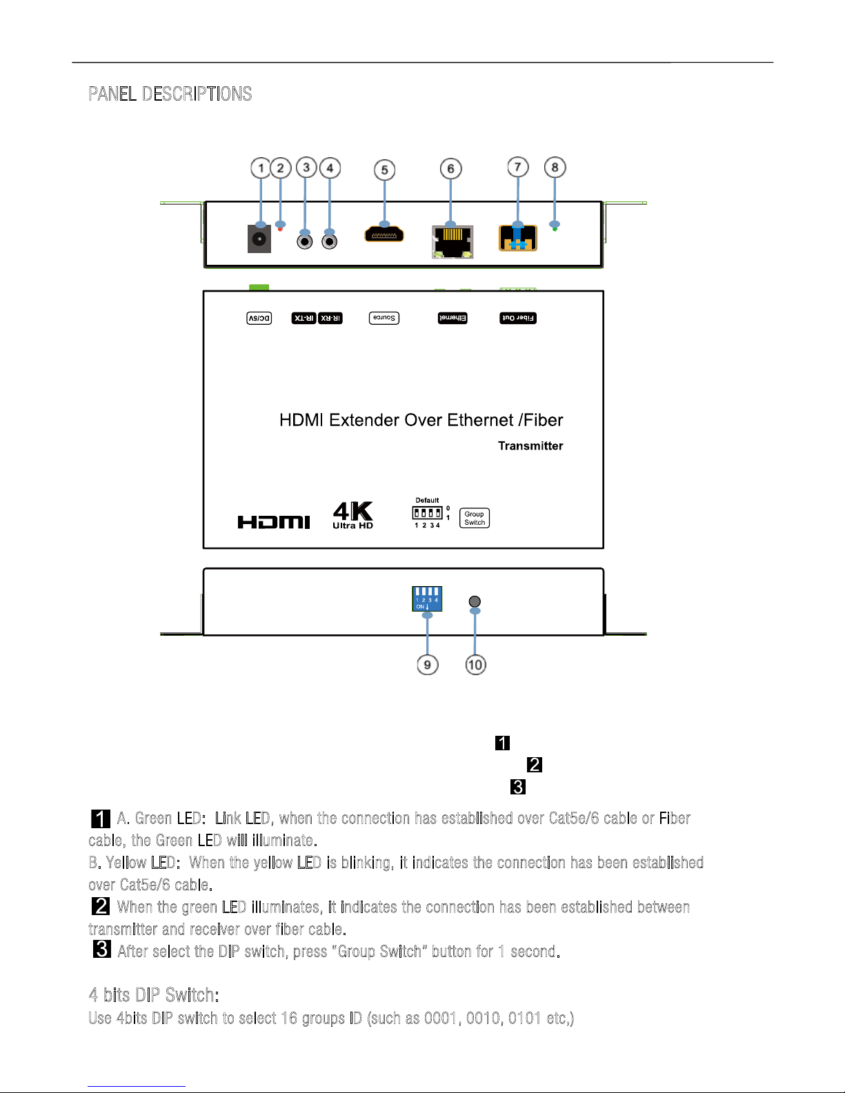
PANEL DESCRIPTIONS
Transmitter Panel
①Power input port ②Power input indicator (Red)
③IR-TX port ④IR-RX port
⑤HDMI input ⑥Ethernet port
⑦Fiber Out ⑧Indicator of status
⑨4 bit Dip switch ⑩Group Switch
A.Green LED:LinkLED,whentheconnection hasestablished overCat5e/6cable orFiber
cable,theGreenLEDwillilluminate.
B.YellowLED: When theyellowLED isblinking,itindicatestheconnectionhasbeenestablished
over Cat5e/6 cable.
When thegreenLEDilluminates,itindicatestheconnection hasbeenestablished between
transmitterandreceiver over fiber cable.
After select the DIP switch,press “GroupSwitch”buttonfor1 second.
4bits DIPSwitch:
Use 4bitsDIPswitch toselect 16groupsID(such as 0001, 0010,0101etc,)

Operating Instructions
4
Receiver Panel
①Power input port ②Power input indicator (Red)
③IR-TX port ④IR-RX port
⑤HDMI Output ⑥Ethernet port
⑦Fiber In ⑧Indicator of status
⑨4 bit Dip switch ⑩Group Switch
A. GreenLED:LinkLED, whenthe connection hasestablishedover Cat5e/6cable orFiber
cable,the Green LED will illuminate.
B.YellowLED:When the yellowLED isblinking,itindicatesthe connection hasbeen established
overCat5e/6cable.
WhenthegreenLEDilluminates, itindicates the connectionhasbeenestablished between
transmitter and receiver overfibercable.
AfterselecttheDIP switch,press “GroupSwitch”button for1 second.
4bitsDIP Switch:
Use4bitsDIPswitch toselect16 group ID (suchas 0001,0010,0101etc,)

Operating Instructions
5
Application1:
Point topoint configuration:
1. Connect one HDMI Cable between the HDMI source and the HDMI input port of Transmitter.
2. Connect one HDMI Cable between the HDMI display and the HDMI output port of Receiver.
3. Connect one UTP Cat5e or better cable between the RJ45 port of Transmitter and RJ45 port of
Receiver. (optional)
4. Connect Fiber cable between the Fiber Output port of Transmitter and Fiber input of Receiver. (optional)
5. Connect 5V2A DC power supplies to both Transmitter unit and Receiver unit.
1. Don’tConnect Cat5e/6 Cable and Fiber Cableatthe sametime.
2.TheFiber moduleisSFP type.
3.Support singlemode Fiber.
4. When change fromCat5e/6cable toFiber cableorfromFiber cabletoCat5e/6
cable,please reconnectingthepower supply.
Application2:
One tomanynetworkconfiguration:
1. Connect one HDMI Cable between the HDMI source and the HDMI input port of Transmitter.
2. Connect one HDMI Cable between the HDMI display and the HDMI output port of Receiver.
3. Connect transmitter and receiver to the Gigabit Ethernet Switch.
4. Power on Transmitter and Receiver with adapter 5V2A, power on the switch with its adapter.
5. If DIP switch of the transmitter is set up: Group ID: 0001, then DIP switch for receiver should be set up
Group ID: 0001

Operating Instructions
6
Application3:
Manyto Manynetwork configuration:
1. Connect one HDMI Cable between the HDMI source and the HDMI input port of Transmitter.
2. Connect one HDMI Cable between the HDMI display and the HDMI output port of Receiver.
3. Connect transmitter and receiver to the Gigabit Ethernet Switch.
4. Use DIP switch to select sources, User can select source channel by DIP switch setting on each
transmitter unit and each receiver.
How touseDIPswitch:
1).Use 4-bit DIP switch to select 16 group ID (such as 0001, 0010, 0101 etc.)
2).Change group ID easily to select the sources.
3).For example, when the devices are connection as below:
Source (DVD1) - TX (TX1) - Gigabit Switch – RX (RX1) - TV1
Source (DVD2) - TX (TX2) - Gigabit Switch – RX (RX2) - TV2
Source (DVD3) - TX (TX3) - Gigabit Switch – RX (RX3) - TV3

Operating Instructions
7
When you set up the group ID for each transmitter just like this:
TX1 (0001)
TX2 (0101)
TX3 (0100)
Now, If you need display Source2 on TV1, then just set Group ID of RX1 0101, same as TX2: 0101 (refer
to Diagram).

Operating Instructions
8
WARRANTY
If your product does not work properly because of a defect in materials or workmanship, our Company
(referred to as "the warrantor" ) will, for the length of the period indicated as below, (Parts(2)Year,
Labor(90)Days) which starts with the date of original purchase ("Limited Warranty period"), at its option
either(a) repair your product with new or refurbished parts, or (b) replace it with a new of a refurbished
product. The decision to repair or replace will be made by the warrantor.
During the "Labor" Limited Warranty period there will be no charge for labor.
During the "Parts" warranty period, there will be no charge for parts. You must mail-in your product
during the warranty period. This Limited Warranty is extended only to the original purchaser and only
covers product purchased as new. A purchase receipt or other proof of original purchase date is required
for Limited Warranty service.
MAIL-IN SERVICE
When shipping the unit carefully pack and send it prepaid, adequately insured and preferably in the
original carton. Include a letter detailing the complaint and provide a day time phone and/or email
address where you can be reached.
LIMITED WARRANTY LIMITS ANDEXCLUSIONS
1) This Limited Warranty ONLY COVERS failures due to defects in materials or workmanship, and DOES
NOT COVER normal wear and tear or cosmetic damage.
The Limited Warranty ALSO DOES NOT COVER damages which occurred in shipment,
or failures which are caused by products not supplied by warrantor, or failures which result from
accidents, misuse, abuse, neglect, mishandling, misapplication, alteration, faulty installation, set-up
adjustments, misadjustment of consumer controls, improper maintenance, power line surge, lightning
damage, modication, or service by anyone other than a Factory Service center or other Authorized
Servicer, or damage that is attributable to acts of God.
2) THERE ARE NO EXPRESS WARRANTIES EXCEPT AS LISTED UNDER "LIMITED WARRANTY COVERAGE".
THE WARRANTOR IS NOT LIABLE FOR INCIDENTAL OR CONSEQUENTIAL DAMAGES RESULTING FROM
THE USE OF THIS PRODUCT, OR ARISING OUT OF ANY BREACH OF THIS WARRNTY. (As examples, this
excludes damages for lost time, cost of having someone remove or re-install an installed unit if
applicable,
travel to and from the service, loss of or damage to media or images, data or other recorded content. The
items listed are not exclusive, but are for illustration only.)
3) PARTS AND SERVICE, WHICH ARE NOT COVERED BY THIS LIMITED WARRANTY, ARE YOUR
RESPONSIBILITY.
Table of contents
Popular Extender manuals by other brands

Citel
Citel EXTender PBXgateway Administrator's guide

Guntermann & Drunck
Guntermann & Drunck DVI-Extender-F installation guide

Renkforce
Renkforce RF-1601828 operating instructions

Marmitek
Marmitek GigaView 911 UHD user manual

Hawking
Hawking Hi-Gain HWREN15 user manual

AMX
AMX DAS-T0804X-SIG installation guide


