4 INT-PP SATEL
5. Installation and start-up
Disconnect power before making any electrical connections.
The expander is designed for indoor installation.
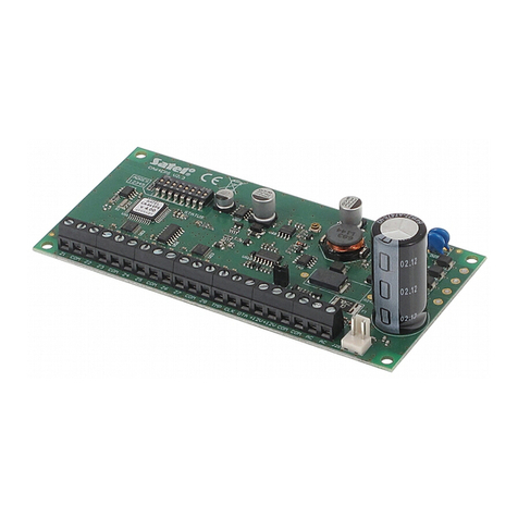
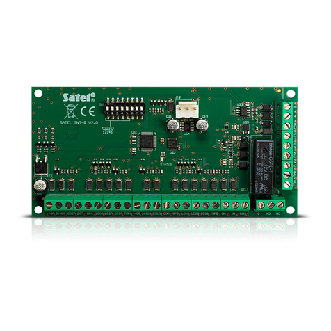
1. Fasten the expander electronics board in the enclosure.
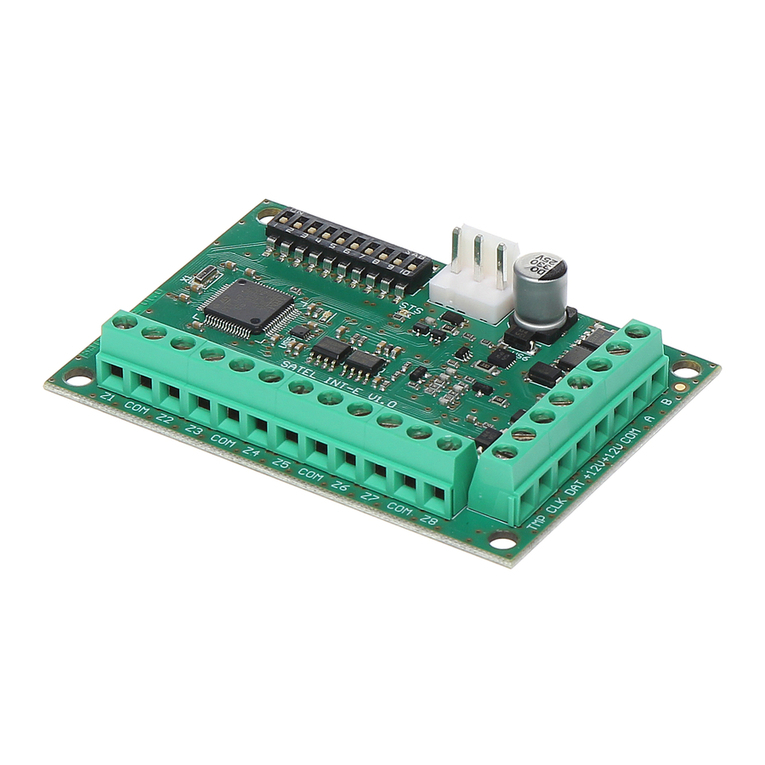
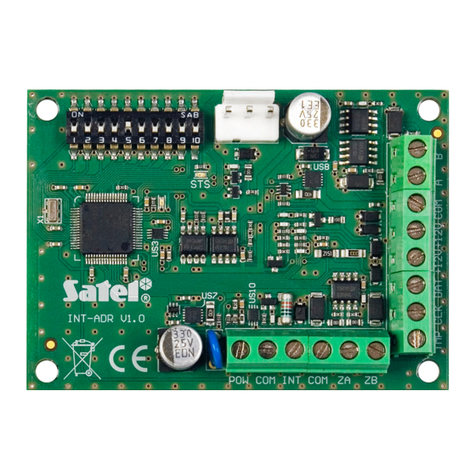
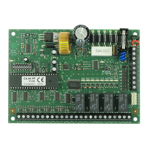
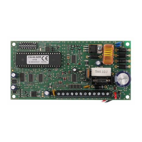
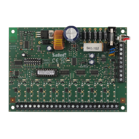
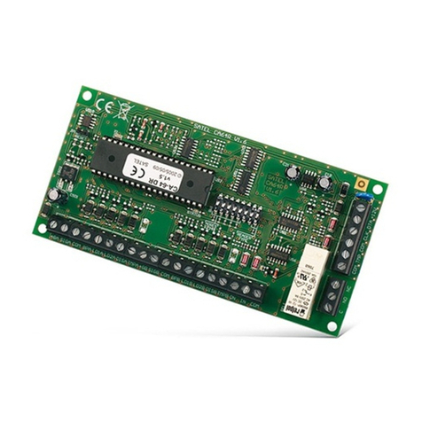
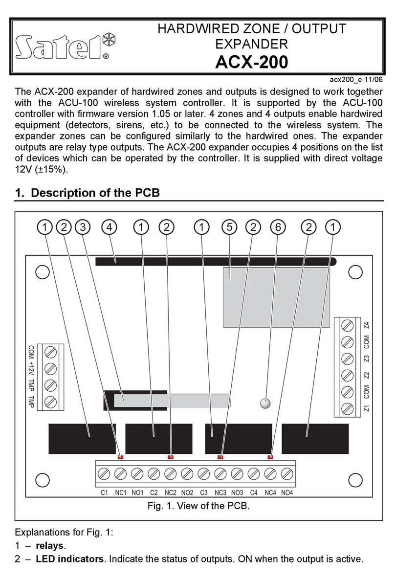
2. Using the DIP-switches, set the suitable expander address and define how it is to be identified.
3. Connect the CLK, DAT and COM terminals to the corresponding terminals of the control panel
communication bus (see: installer manual for alarm control panel). It is recommended that an
unshielded non-twisted cable be used to make the connection. If you use the twisted-pair type of
cable, remember that CLK (clock) and DAT (data) signals must not be sent through one pair of
twisted conductors. The conductors must be run in one cable.
4. If the expander is to supervise the enclosure tamper contact, connect the wires of tamper contact
to the TMP and COM terminals. If the expander is not to supervise the enclosure tamper contact,
connect the TMP terminal to the expander COM terminal.
5. Connect detectors to the expander zones (for description of how the detectors should be
connected, please refer to the installer manual of alarm control panel).
6. Depending on the selected method of expander powering, connect the dedicated power supply
unit to the connector on expander electronics board or connect the power leads to the +12V and
COM terminals (the expander may be powered directly from the control panel, from an expander
with power supply or from a power supply unit).
The expander must not be powered from both sources at the same time.
7. Power on the alarm system.
8. Start the identification function in the control panel. After expander identification is completed, the
zones and outputs will be assigned their respective numbers in the alarm system. The zone and
output numeration rules are described in the control panel manual. The control panel monitors
presence of the identified modules. If the module is disconnected from communication bus,
position of DIP-switches is changed, or the device is replaced with another one with DIP-switches
set in the same way, a tamper alarm will be triggered.
9. Configure the outputs and check that they operate properly (the output status is indicated by
LEDs).
10. Power off the alarm system.
11. Connect to expander outputs the devices whose operation is to be controlled by the control panel.
12. Power on the alarm system.
6. Updating the expander firmware
Using the RS-485 bus, connect the expander to the ACCO-USB converter, and then connect the
converter to the computer (see: ACCO-USB converter manual). You can find a program for updating
the expander firmware and a detailed description of the firmware update procedure on the
www.satel.eu website.
SATEL sp. z o.o. • ul. Schuberta 79 • 80-172 Gdańsk • POLAND
tel. + 48 58 320 94 00
info@satel.pl
www.satel.eu
