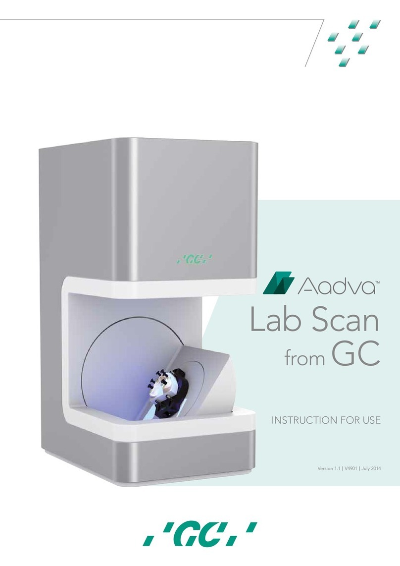
gc Aadva Lab Scanner 2 User manual

Simplicity
Accuracy
Productivity
Aadva Lab
Scanner 2
from GC
Manual
Date of issue December 2019

2
Dear customer,
Thank you for choosing a product from GC!
If you require additional information or if you have any questions about the device,
please contact your GC local office.
We wish you much joy with your Aadva ALS 2 scanner!
Your Aadva team
CHANGES AND SERVICE
We reserve the right to implement product changes as part of continuous improvement and technical progress and to
make changes to this documentation. You can find the current version of this documentation on our homepage:
https://digital.gceurope.com/products/aadvalabscan/
On request we are also glad to send you a printed paper version of the documentation. Please send us an e mail to
digitalservices.gce@gc.dental
BRANDS AND TRADEMARKS
Windows, .NET Framework and Visual C++ are registered trademarks of Microsoft Corporation.
FlyCapture and UpdatorGUI are registered trademarks of Point Grey Research, Inc.
exocad is a registered trademark of exocad GmbH, D-64293 Darmstadt.
Adesso Split and Artist/arTO are registered trademarks of K. Baumann, D-75210 Keltern.
SAM is a registered trademark of SAM Präzisionstechnik GmbH, D-82131 Gauting.
Artex is a registered trademark of Amann Girrbach AG, A-6842 Koblach.
Gamma is a registered trademark of Gamma medizinisch-wissenschaftliche Fortbildungs-GmbH, A-3400-
Klosterneuburg.
PROTAR is a registered trademark of KaVo Dental GmbH, D-88400 Biberach/Riß.
Denar is a registered trademark of Whip Mix Corporation, Louisville, KY 40209, USA.
Triple Tray is a registered trademark of Premier Dental, Plymouth Meeting, PA 19462 U.S.A.
Where products belonging to other owners are referenced, we wish to point out that these are brands of the relevant
owners that are protected by copyright laws.
Royalty-free icons and illustrations from the Flaticon.com, Fotolia.com, Freepik.com and Pixabay.com image agencies
were used in this operating manual.

3
Aadva Lab Scanner 2
Manual
Table of contents
1. About 4
Introduction 4
Warnings 5
2. For your safety 6
2.1. Proper use 6
2.2. General safety instructions 7
2.3. Symbols on the device 12
3. Scope of delivery 13
4. Device components 15
4.1. Front view 15
4.2. Internal view 15
4.3. Views of the accessories (standard scope of delivery) 17
4.4. Connections and type plate (rear view) 18
5. Setup and commissioning of the scanner 19
5.1. Choosing a workstation 19
5.2. Unpacking the scanner 19
5.3. Connecting the scanner 20
5.4. Aadva Scan installation 21
6. The object holder system 27
6.1. Overview 27
6.2. Matting the surface with 3D scan spray 28
7. Positioning of a single jaw model 29
7.1. Inserting a jaw model with a Multisplit mounting plate 29
7.2. Inserting a jaw model with an adapter plate 30
7.3. Inserting a jaw model with an object holder 32
7.4. Fastening gingiva, squeeze bites, scanbodies or wax-ups 34
34
8. Positioning of non-articulated occlusion models 35
8.1. Fastening an occlusion model with a rubber band 35
8.2. Fastening of an occlusion model with an occlusion clamp 36
9. Positioning of articulated occlusal models 37
9.1. Positioning of an occlusal model with an articulator 37
10. Positioning tooth stump models with 39
the Multi die adapter 39
11. Positioning of a Triple Tray® impression 41
12. Positioning objects (universal mode) 44
12.1. Fastening objects on the flexible object holder 44
12.2. Inserting the object holder 46
12.3. Removing the object holder 46
13. Positioning the calibration model 47
14. Operating principle of the scanner 48
14.1. Operation via touchscreen 49
14.2. Switching between LR and HR mode 49
15. Device maintenance 50
16. Faults and repairs 51
17.Environmentally-friendly disposal 52
17.1. Disposal of the packaging 52
17.2. Disposal of the device 52
18. Technical specifications 53
20. Glossary 54

4
1. About
Please read through this operating manual carefully.
GC accepts no liability for damages due to failure to comply with the operating manual.
Introduction
ALS 2 combines unique scan features with robust scanning hardware that will simplify your daily lab work.
ADVANTAGES
Constant & reliable accuracy
Full color scanning
Speed and quality
HD 5 Mpx camera
Full exocad® integration
Open files (STL and PLY)
Complete jaw scanned in 22 s
Touchscreen
4 μ accuracy according to ISO 12836
TECHNICAL DATA
Measurement field (X × Y × Z) 85,2 × 58,1 × 82 mm
5 Mpx Camera
Blue light LED sensor technology
Stripe light triangulation
Monochrome texture scan
Color texture scan
Fully automated Z-axis
Articulator scan
Multi die scan
Triple Tray® scan
Impression scan
Twin Tray scan

5
Aadva Lab Scanner 2
Manual
Figures showing equipment and screenshots from the software are used for illustration purposes.
The screenshots show realistic examples but do not contain actual data.
In this manual the numbers are given according to the decimal system with decimal places.
Units of measurement comply with the international system of units (SI).
Further information as well as measurement converters can be found on the Internet.
Measurement Unit Abbreviation
Mass/weight Kilogram kg
Gram g
Length Meter m
Centimeter cm
Millimeter mm
Micrometer µ
Angle Degree °
Time Hour h
Minute m
Second s
Electrical power Watt W
Electrical voltage Volt V
Alternating current AC
Electrical frequency Hertz Hz
Gigahertz Ghz
Electrical current Ampere A
Protection class International Protection IP
1st digit: solids protection;
2nd digit: fluids protection
Temperature Degree Celsius °
Memory (PC) Random-Access Memory RAM
Data volume Megabyte MB
Gigabyte GB
CAD data format Polygon file format PLY
Standard Triangulation Language STL
American Standard Code for Information Interchange ASCII
Mesh MSH
Point Cloud Measurement PCM
Picture element Pixel Px (monitor)
dpi (print)
Megapixel Mpx
Warnings
Warnings provide information on how damage to objects and injury to persons can occur and give instructions on how
to avoid risks. Warnings are categorized into four levels depending on the severity of the possible consequences.
NOTE
This combination of signal word and symbol warns you about possible material damage that might occur
if the instructions are not followed correctly.
CAUTION
This combination of signal word and symbol warns you about possible minor injuries that might occur
if the instructions are not followed correctly.
WARNING
This combination of signal word and symbol warns you about severe to lethal injuries that might occur
if the instructions are not followed correctly.
DANGER
This combination of signal word and symbol warns you of dangerous situations which could lead directly
to death or severe injuries.

6
2. For your safety
2.1. Proper use
USE IN DENTAL TECHNOLOGY
The proper use of the ALS 2 is the optical three-dimensional measurement of human jaw models. The scanners can be
used in the field of orthodontics and prosthetics for all kinds of reconstructions, as well as for archiving purposes.
Jaw models in occlusal relationship can be scanned with reference to cephalic presentation, as well as dental
registrations (bite registrations) and dental casts (wax-up), and also reference bodies (scan bodies) screw-retained
in the model.
USE AS A UNIVERSAL SCANNER
The proper use of the ALS 2 scanner is the optical three-dimensional measurement of objects with a maximum size of
85,2 × 58,1 × 82 mm (XYZ). The maximum weight of the objects must not exceed 0.938 kg. The scanners can be used
for the production of, for example, tools, jewelry or toys as well as to test the accuracy of replicas.
MATERIAL CHARACTERISTICS
The ALS 2 scan materials with a dry/ matted, opaque surface of white, saffron, gold, blue, beige, yellow and pink color.
Reflective or dark surfaces can be scanned if they are previously treated with 3D scan spray. Moveable parts of the
models must be able to be immobilized, so that they do not change their position during scanning.
IMPROPER USE
The ALS 2 is not designed to scan models made of transparent materials, models of non-dimensionally stable
or unstable materials or living organisms.
The ALS 2 is not suitable for use in an environment heavily burdened by emissions (e.g. dust or paint). Their use in
a private environment is also excluded.
GC strongly advises to avoid any other than the proper use. GC assumes no liability for damages due to an improper
use of the scanner and/or non-observance of the safety instructions indicated in these operating instructions.

7
Aadva Lab Scanner 2
Manual
2.2. General safety instructions
USER QUALIFICATION
Users who set up, commission or operate a GC scanner require special knowledge for the safe operation of the
scanner. This knowledge can be acquired by means of the following measures:
Read and follow these operating instructions, in particular the instructions concerning setup, commissioning and
cleaning of the scanner.
Participate in an induction or training course.
Comply with local laws, regulations, occupational safety and accident prevention rules concerning your scanner’s
workplace.
Make sure that all devices and cables pass the periodic safety checks for electrical appliances. Replace damaged
devices and cables immediately. Make sure that the technical specifications of power cables are adequate.
CONSTRUCTIVE PROTECTIVE MEASURES
The scanner has been developed and manufactured in compliance with the applicable safety standards and with the
greatest possible care to ensure safe operation and to protect the user against injuries.
A fuse to protect the device from overvoltage is integrated into the device.
PROTECTION AGAINST INJURIES
Despite the protective measures included in the design, some residual risks that might lead to injuries cannot be
excluded. In this section you will learn what measures you can take to protect yourself and other people.
Electric shock and short circuit
WARNING
Risk of injury due to electric shock
Fire hazard due to short circuit
A technical defect of the cable or of individual components of the scanner can cause an electric shock or a short
circuit. This can result in a fire.
• Make sure that no electrical equipment can come into contact with water/moisture. Should this however happen at
some time, disconnect the power plug immediately. Dry the affected parts with a soft microfiber cloth.
• Do not work with defective devices or cables under any circumstances.
• Operate electrical equipment only at the recommended operating temperatures.
• Only use the supplied cable or the corresponding spare parts.
• If electrical devices are not used over a longer period, such as overnight, turn them off and disconnect the power
plug from the socket.
Magnetic fields
WARNING
Health hazard due to magnetic fields
The scanner and its accessories include magnetic components. Magnetic fields can be health-damaging.
• Persons with implants, in particular heart pacemakers, may only operate the scanner and its accessories with
express medical permission.
Stripe light
WARNING
Health hazard due to stripe light
The scanner works with stripe light. Constant visual contact with stripe light can trigger epileptic seizures, migraine
or similar conditions.
• Individuals suffering from such conditions should cover the scanner during operation.

8
Blue light
WARNING
Health hazard due to LED light with high blue content
Recent studies show that light with a high blue content can lead to permanent retinal damage or contribute to it.
White LED light also has a high blue content. Users should therefore avoid prolonged visual contact with white
or blue LED light.
• The scanner emits white light or blue light with each measurement.
Cover the scanner during operation.
• Wearers of glasses can protect their eyes with glasses with a blue light filter.
Falling
CAUTION
Risk of falling due to packaging materials
The scanner is extensively packaged for protection against transport damages. The packaging can be an obstacle
during setup and can cause falls.
• Do not leave packaging materials lying on the ground.
• Before transporting, move all obstacles out of the way.
Carrying
CAUTION
Risk of injury due to incorrect carrying
Due to its size and weight, we recommend that two people should unpack and set up the scanner. In particular,
shorter individuals can be injured if they lift or carry the scanner by themselves without any help.
• Two people should lift the scanner out of its packaging.
• Two people should carry the scanner.
• To transport the scanner, always grasp it by the bottom corners.
Crushing
CAUTION
Risk of injury due to the mechanical parts of the scanner
You can get crushed by the mechanical parts of the scanner.
• Only put your hands inside the scanner when the axes have stopped. Should the axes not stop at the end of
a scanning process, turn off the scanner and disconnect the power plug.
Entanglement
CAUTION
Injury due to entanglement of clothing, jewelry or hair
Loose clothing, jewelry or long hair can get entangled in the mechanical parts of the scanner. Due to motion, objects
and hair can get entangled inside the scanner. This can lead to injury.
• Do not wear any loose garments such as shawls and ties, or jewelry like long necklaces, at the scanner’s workplace.
• Comb your hair into a firm pigtail, for example.
• However, should a piece of clothing, hair or jewelry get entangled among the moving parts of the device, turn the
scanner off immediately. Disconnect the power plug before removing the entangled part.

9
Aadva Lab Scanner 2
Manual
PROTECTION AGAINST MATERIAL DAMAGES
Despite the protective measures included in the design, some residual risks that might lead to material damages (loss of
data or damage to devices) cannot be excluded. In this section you will learn what measures can be taken against material
damages.
Optics/Electronics
NOTE
Damage to optical and electronic components due to touching, humidity, dirt and cleaning
The optical and electronic components in the interior of the scanner are highly sensitive. Any touch, as well as dirt,
moisture and cleaning agents can damage them.
• Do not touch any optical and electronic components,
• Protect the optical and electronic components against soiling by covering the scanner.
• Never use the 3D scan spray inside the scanner.
• If the optical or electronic components have to be cleaned, do not do it yourself. Please contact GC.
Carrying
NOTE
Damage to the scanner due to incorrect carrying
The front upper corners are not suitable to be used as carrying handles. If you carry the scanner by the front upper
corners, they can come off and the scanner will fall and get damaged. If you reach into the front upper corners,
you can damage sensitive components, especially the camera and the sensor.
• To transport the scanner, always grasp it by the bottom corners, never by the front upper corners.
Cleaning agents
NOTE
Damage to surfaces due to unsuitable cleaning agents
Paper towels, coarse cotton cloth, detergents, polishing paste, etc. leave scratches on the sensitive surfaces.
• Only use the recommended materials for cleaning.
Moisture
NOTE
Material damages due to moisture
Constant contact with moisture can damage sensitive materials.
• Only operate the scanner at a dry workplace.
• Avoid any contact with water/moisture. Should this however happen at some time, disconnect the power plug
immediately. Immediately wipe off any water/moisture using a soft microfiber cloth.
Climate
NOTE
Measuring errors due to unsuitable climatic conditions
The scanner is designed solely for use inside dry, closed rooms. Precise measurement results are only achieved
by the scanner under suitable climatic conditions. Too much heat causes measurement errors and overheating of
the scanner. Overheating can permanently damage the scanner.
• Only operate the scanner at temperatures of 18°C – 30°C.
• Only operate the scanner in low humidity conditions.
• Avoid direct sun exposure at the workplace.
• Reduce cold, heat and high humidity, e.g. through the use of air conditioners or sun protection.

10
Reflections
NOTE
Measuring errors due to reflections on the measured object
Strong extraneous light leads to unwanted reflections on the measured object.
This affects the accuracy of the measurements.
• Select a workplace away from a window or not affected by high levels of artificial lighting.
• Cover the opening during the scanning process, e.g. with light-tight foil/dust-cover.
Vibration
NOTE
Measuring errors due to vibrations
The surface on which the scanner is placed must not vibrate. Vibration will cause inaccurate measurement results.
• Place the scanner on a sturdy, stable base able to support at least twice the weight of the scanner, i.e. 2 x 23 kg.
• Stabilize the base by means of a strutted under frame or by attaching it to a stable wall.
Calibration
NOTE
Inaccurate measurements due to failure to calibrate or use of a damaged calibration model
The measuring accuracy of the scanner is only guaranteed if the scanner is calibrated. This operation requires the use
of a calibration model and the associated default values.
The calibration model can be mechanically damaged. This can only be tolerated in the border area.
• Perform the calibration of the scanner after commissioning, after transporting it and whenever the software asks
you to do so during operation.
• Only start the procedure when the values registered in the software match the values of the calibration model.
• Check whether the calibration model is damaged at a central location.
• Only use the calibration model if it is in perfect condition.
Model fastening
NOTE
Damage to the scanner and the models due to missing or incorrect fastening
Due to the motion of the axes inside the scanner, unsecured or incorrectly secured models will fall down during the
scanning process.
• Do not place any objects on top of or inside the scanner.
• Never place unfastened models inside the scanner.
• Only use the included object holder or approved accessories to fasten models.
• When fastening occlusal models with rubber bands, only use stable, unused rubber bands.
Thin or porous rubber bands can tear.
• Always fasten models on the flexible object holder and the Multi die adapter using adhesive pads made of modeling
clay.
• Only place stump models prepared with metal pins inside the Multi die adapter.
• However, should a model still fall down, turn off the scanner immediately.
Then remove the model or all broken pieces from the interior of the scanner.
Adhesive materials
NOTE
Damages to models due to unsuitable adhesive materials
Models, object holders and the scanner get soiled or are even damaged through the use of adhesive tape, instant
glue or similar products.
• Only fasten models using adhesive pads made of modeling clay.

11
Aadva Lab Scanner 2
Manual
Articulators
NOTE
Damages to the scanner and models due to incorrectly positioned articulators
Articulators are not to be fastened inside the scanner. This is possible because articulators can be scanned with
reduced axis motion.
• Only place an articulator inside the scanner when the software asks you to do so.
• Always place an articulator with the front side first inside the scanner.
• Always place an articulator with all legs resting on the system plate.
• Remove an articulator immediately when the software asks you to do so.
• However, should an articulator still fall down, turn off the scanner immediately.
Then remove the articulator or all broken pieces from the interior of the scanner.
USB cable
NOTE
Data loss due to a too long USB cable
The transfer of data between the scanner and the PC is affected by the length of the USB 3 cable.
• Only use the supplied USB 3 cable or an original spare part with the corresponding length (max. 2 meters).
Magnetic fields
NOTE
Data loss due to magnetic fields
The scanner and its accessories include magnetic components. Metal-containing technical devices and data carriers,
e.g. credit cards, can be impaired in their function or even permanently damaged through contact with magnets.
• Make sure there is an adequate distance between metal-containing technical devices/data carriers and the magnet.
RESPONSE IN CASE OF A DEFECT
You must not work with a defective system. Damage to the scanner, its accessories or a faulty function have occurred
with high probability if:
– parts have been visibly damaged
– one or more of the moving axes continue to rotate or rotate in an uncontrolled way
– the calibration procedure fails
– measuring errors occur despite performing all work steps
– the software displays an error message.
• Follow the instruction in an error message.
• Check the connections. If applicable, replace the USB slots.
• End the software, switch off the scanner and the PC and restart the system.
• Check whether the software is installed correctly.
• Check the calibration data.
• Follow the instruction for device maintenance.
• Update your system. Check whether all important Windows updates have been installed.
• Ensure that your computer is free of viruses and malware.
• Allow the execution of Aadva Scan in your virus protection software.
• If none of these measures solve the problem, repeat with another computer to exclude a computer fault.
If problem persists please contact the GC support via digitalservices.gce@gc.dental.

12
2.3. Symbols on the device
WARNINGS
Warning against hand injuries
If a body part enters the scanner opening, there is a risk of crushing.
Always exercise care when reaching into the scanner to place the object holder.
Electrical voltage warning
This sign warns of electrical voltage inside the scanner.
The rear cover of the scanner may only be removed by skilled personnel if the mains plug has been disconnected
from the mains.
Do not touch
This symbol refers to the calibrated optical system.
This must never be touched or cleaned as it could be damaged in the process.
OTHER
CE label
The CE label on the type plate documents that the European directives that are applicable to the device
were complied with at the time of issue of the CE certificate.
EMC labelling
The electromagnetic compatibility of the device was checked for compliance with the limit values according
to the European standard and the measuring methods for radio interference of industrial, scientific and
medical high frequency devices. Labelling as “Class A” states that the device meets the standard for
commercial applications.
Fuse
Symbol for an overcurrent protection device, installed in a mains connection, suitable for AC voltage 100
- 240 Volt and a frequency of 50/60 Hertz.
USB
USB
Symbol for a USB connection, also for a camera connection.
Protective grounding
Symbol for connection to an external conductor to protect against electric shock in the event of a fault or
connection of protective grounding (mass).
On/Off switch
Symbol for a switch to turn the device on and off.

13
Aadva Lab Scanner 2
Manual
3. Scope of delivery
The scope of delivery includes the following components:
ALS 2 940066
1 scanner
– Touchscreen
– Blue light LED
– LED status bar
– 5 Mpx camera
Accessory case:
1 object holder with knurled screw
1 object holder, flexible, with large plate
1 multiDie adapter
1 Triple Tray® impression holder
1 4 teeth bar for Twin Tray impression scans
2 packs of adhesive pads, extra-strong*
1 calibration model
1 data carrier
Accessory box:
1 power cable
1 USB cable
* UHU patafix PROPower or a comparable brand product made of removable, reusable adhesive glue pads
CONTENTS OF THE DATA CARRIER
ALS 2
Calibration data
Aadva Scan installer
PACKAGING
The packaging consists of the following components:
– top insert with foam protection
– accessory box
– bag (protective cover for the scanner)
– carton box
– foam insert
– accessory case

14
OPTIONAL ACCESSORIES
In the case of ALS 2, all components are already included in the standard scope of delivery.
The exception being articulators (not an accessory) as well as adapter plates for articulators (chargeable accessory).
Please contact your local GC office to order additional accessories.
Article number Product Name
Below accessories included in standard packaging
940437 Multi die Adapter
940438 Triple Tray® Impression holder
940439 3D calibration model
940440 Object holder flexible, with adhesive pads
4 teeth bar for Twin Tray impression scans
Optional accessories
990570 Dust cover ALS 2
940441 Adapter plate AdessoSplit to Gamma
940442 Adapter plate AdessoSplit to SAM
940443 Adapter plate AdessoSplit to KaVo Protar
940444 Adapter plate AdessoSplit to Whip Mix
940445 Occlusion clip for upper and lower jaw
For safety reasons, please use only the replacement or additional items mentioned here. For parts that are not listed
as replacement items, e.g. cables, please replace them with commercially available products with the same technical
specifications.
PCs must meet the technical specifications.
SUPPORTED ARTICULATOR SYSTEMS
Articulators are available at specialist dental dealers, but cannot be purchased from GC as accessories for the scanner.
All conventional articulators can be used for vestibular scans with articulated occlusion models. Condyle-related
measurements are possible with the articulators of the following manufacturers:
– AMANN GIRRBACH Artex®
– Baumann Dental Artist/arTO®
– SAM® AXIOSPLIT®
– GAMMA® Reference
– Whip Mix Denar®
– KaVo PROTAR®
Other articulators can be used for mean value measurements.

15
Aadva Lab Scanner 2
Manual
4. Device components
4.1. Front view
DETAILED VIEW OF THE TOUCHSCREEN
4.2. Internal view
1. Touchscreen
2. Opening
1. Starting status (logo): Operation from the
PC possible
2. Operating status: Start button and process
display (see above)
Start button: Operation from the device
possible
Process display: The device is working, no
user action possible
1. Optics (camera and 3D sensor)
2. Z-axis (electromotive up and downwards movement 0 - 30 mm)
3. Swivel axis (electromotive lateral movement 0 - 45°)
4. System plate with Adesso Multisplit base plate
5. Rotary axis (electromotive rotation up to 315°)
1
5
4
2
3

16
DETAILED VIEW OF THE SYSTEM PLATE
DETAILED VIEW OF THE STATUS LED
1. Turntable with non-slip rubber mat for the
placement of articulators
2. Adesso® Multisplit base plate for mounting
object holders, adapter plates and
Multisplit mounting plates
1. Status LED on the swivel axis
White Hibernation (equivalent to the logo or screen saver on the touchscreen)
Green Operation (corresponds to the start button and the process display on the touchscreen)
1
2
DETAILED VIEW OF CAMERA, SENSOR AND LED
1. Projector
2. Camera
1
2
1

17
Aadva Lab Scanner 2
Manual
4.3. Views of the accessories (standard scope of delivery)
Object holder with knurled screw
Flexible object holder with large plate,
fixing with adhesive pads
Multi die adapter, fixing with adhesive pads Triple Tray® Impression Holder
Calibration model
(Example image)
Adhesive glue pads, extra-strong
(Example image)
Power cable USB cable
Data carrier
(Example image)

18
4.4. Connections and type plate (rear view)
3
1. ON/OFF switch
2. Functional grounding
3. USB 3.0 connection for device control and camera
4. Mains connection with fuse
4
1
2
Type plate
The type plate with technical
information such as serial number
of the device, place and date of
manufacture is located on the
rear.
The serial number of the 3D
sensor is given on a separate
label.

19
Aadva Lab Scanner 2
Manual
5. Setup and commissioning of the scanner
5.1. Choosing a workstation
OBSERVE THE SAFETY INSTRUCTIONS!
• When choosing a workstation, please note that the ALS 2 is an EMC Class A devices suitable for use in a commercial
environment.
• Choose a stable work desk that is big enough to allow the scanner to be connected to a PC. The weight of the
scanner is 23 kg and its setup dimensions are 432,6 × 436,8 × 364,5 mm (W x H x D).
• Ensure easy access to the rear as this is where the ON/OFF switch is located.
• Ensure that there are enough and sufficiently fused mains sockets for all the devices. After consultation
with an electrician, you can use an approved extension cable, a multiple power socket and a socket
adapter (additional electrical devices not included in the scope of delivery).
5.2. Unpacking the scanner
OBSERVE THE SAFETY INSTRUCTIONS!
The scanner is delivered in a foldable carton box. The carton box is equipped with an impact and tilt indicator (outside)
and clad with a foam transport protection (inside).
Keep the packaging for possible transport or return. The original packaging is precisely adapted to the scanner and
thus offers the best protection against transport damage.
• Check the outer packaging for visible damage immediately on receipt.
• If an indicator indicates a careless storage or even any shipping irregularities or if damage is evident on the
packaging, please inform the delivery company and GC.
Follow the instructions provided by the delivery company and GC before continuing to unpack the device.
• Transport the scanner in the packaging as close to the workstation as possible.
• Remove the accessory case and place it aside. The accessories may be on top or below the scanner.
• Remove the foam board.
Due to the dimensions and weight GC recommends carrying by two persons.
Never hold it by the front upper corners or inner parts because sensitive technical components are placed there.
The protective bag prevents incorrect gripping.
• Position yourself with a second person to the right and left of the scanner.
• Place one hand each under the front and rear corner of the scanner.
• Lift the scanner simultaneously.
• When carrying, incline the scanner slightly backwards.
Setting the scanner down
• Set the scanner down carefully and in a straight position at the place of installation.
• Remove the protective bag.
• Immediately check the scanner and the accessories for completeness and any visible damage.
If the scope of delivery is not complete or if one of the supplied parts shows visible damage, contact your GC digital
specialist. Follow the instructions provided by GC before continuing with the setup.
Position of person 1 Position of person 2

20
5.3. Connecting the scanner
The scanner requires a mains connection and a PC connection. The scanner does not work without a software.
The connections are located on the rear of the scanner.
• Connect the type B plug of the USB 3.0 cable to the USB 3.0 port of the scanner.
• Connect the device plug of the power cable to the corresponding mains socket on the scanner.
CABLE CONNECTIONS OF THE SCANNER
• Connect the flat type A plug of the USB 3.0 cable to a free USB 3.0 port of the PC.
The scanner is operational.
• Switch on the scanner using the power switch.
The power switch is in position I.
The touchscreen displays the starting status (logo).
• Connect the mains plug of the power cable to the mains. It is not necessary to use an adapter to adjust the voltage
as an AC-DC device is integrated in the scanner.
1
2
1. USB connection
2. Mains connection
Table of contents
Other gc Laboratory Equipment manuals
Popular Laboratory Equipment manuals by other brands

Heidolph
Heidolph REAX top instruction manual
Labnet
Labnet BioPette E BE20-1 series Operation manual
IKA
IKA RET control-visc operating instructions
cytiva
cytiva F9-R instructions
D&H
D&H Lifelabs AquaSolvo Eco AAE-5005 Series instruction manual

ThermoFisher Scientific
ThermoFisher Scientific Thermo Scientific Sorvall Legend XF instruction manual

NuAire
NuAire AllerGard NU-620-300 Operation & maintenance manual
TA Instruments
TA Instruments DSC Autosampler CE Operator's manual

Mocom
Mocom Autoklav B Futura 28 Liter manual
Miele
Miele FFK APCL S installation instructions

Thermo Scientific
Thermo Scientific Cryofuge 5500i GMP Instructions for use

erlab
erlab Captair 832 Smart Assembly instructions
