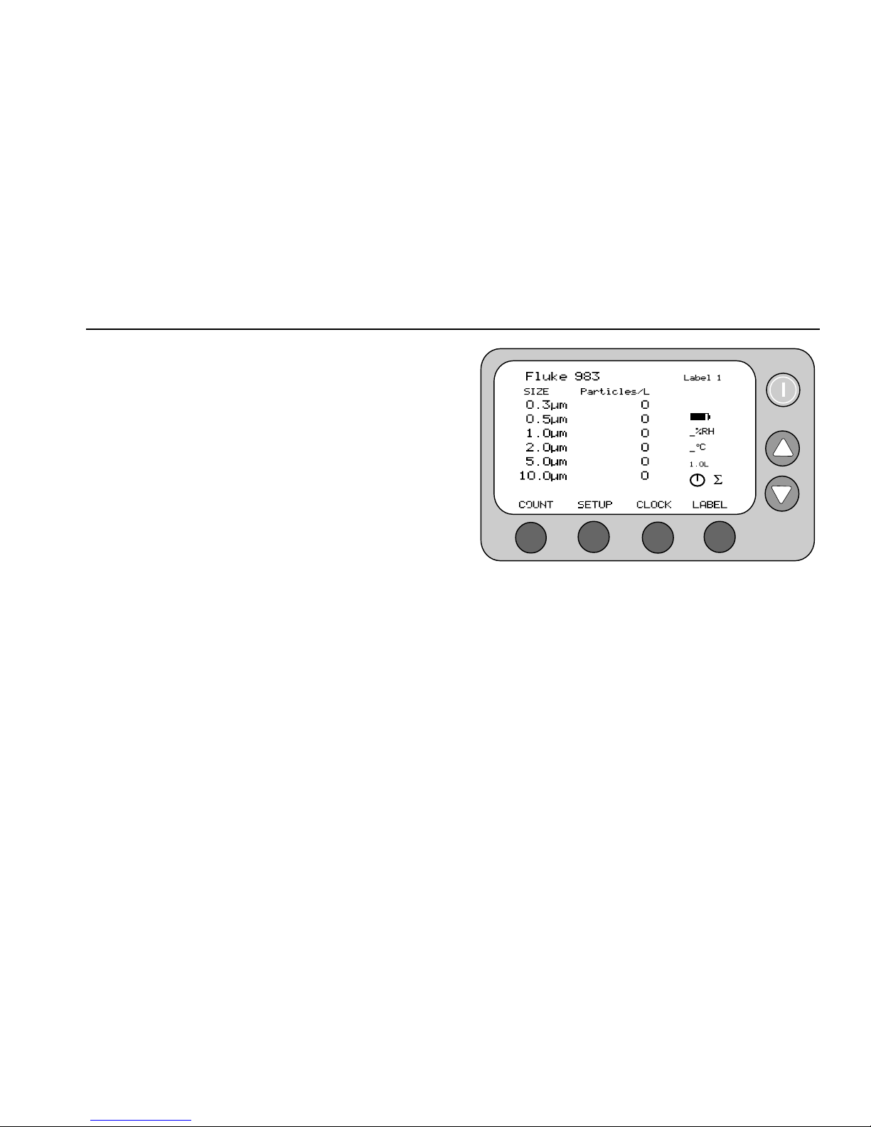
Fluke 983 User manual

®
Fluke 983
Particle Counter
Users Manual
PN 2414721
January 2005
© 2005 Fluke Corporation. All rights reserved. Printed in U.S.A.
All product names are trademarks of their respective companies.
Advanced Test Equipment Rentals
www.atecorp.com 800-404-ATEC (2832)
®
E
s
t
a
b
l
i
s
h
e
d
1
9
8
1

1
Fluke 983
Particle Counter
Introduction
WWarning
Read “Safety Information” before using the
Fluke 983 Particle Counter.
The Fluke 983 Particle Counter (“The Particle Counter”) is
a portable instrument that measures and reports air
contamination. It holds 5,000 samples in memory and
records the date, time, counts, sample volume,
temperature, and relative humidity of each sample. The
data can be easily downloaded to a personal computer
using the interface cable adapter, cable, and Fluke 983
Utility Software provided with the unit.
Applications
The Particle Counter can be used for:
•Monitoring cleanrooms
•Indoor air quality investigations
•Monitoring gowning rooms
•Testing filter seals
•Locating particle contamination sources
•Monitoring particle size distributions

Fluke 983
Users Manual
2
Safety Information
A Warning identifies a condition or action that pose
hazard(s) to the user; a Caution identifies a condition or
action that may damage the Particle Counter or the
equipment under test.
Read the entire Users Manual before using the Particle
Counter.
Safety symbols used in this manual and on the Particle
Counter are displayed in Table 1.
Table 1. Symbols
Symbol Meaning
W Risk of Danger. Important information. Refer to manual.
P Conforms to relevant European Union directives.
WWarning
To avoid electric shock, injury, or damage to
the Particle Counter, follow these safety
guidelines:
•Use the Particle Counter only as
described in the Users Manual,
otherwise the protection provided by the
instrument may be impaired.
•Do not use the Particle Counter in
explosive atmospheres.
•The Particle Counter contains no user-
serviceable parts. Do not open the
instrument. For service and battery
replacement, the instrument must be
sent to Fluke. See “Contacting Fluke”.
•Have the Particle Counter serviced only
by qualified service personnel.
•Inspect the Particle Counter before use.
Do not use it if it appears damaged.
•Always use the ac adapter/charger and
connector (supplied with the Particle
Counter) appropriate for the voltage and
outlet of the country or location in which
you are working.

Particle Counter
Compliance
3
WCaution
To avoid possible damage to the Particle
Counter:
•Avoid using the Particle Counter in an
excessively dirty or dusty atmosphere.
Excessive particle intake can damage the
Particle Counter.
•Remove the Isokinetic-Probe Cover (the
black cap) before use. Not doing so can
damage the Particle Counter.
•Do not use a wrench to connect or
disconnect the Isokinetic Probe or intake
nozzle. The connection should be finger
tight.
•If using the tilt stand, hold the
instrument while using the keypad.
Compliance
The Particle Counter complies with:
P, JIS B9921: 1997, 89/336/EEC, 73/23/EEC, EN61326:
1997, EN60825-1:2001, Federal Standard 209E
Quick Start
The Particle Counter may be used directly out of the box.
To immediately use the Particle Counter:
1. Read “Safety Information”
2. Remove the Isokinetic Probe Cover (the black cap)
3. Press the POWER keypad
4. Press 1to start sampling
Be sure to read the entire Users Manual for more detailed
information.

Fluke 983
Users Manual
4
Shipping Contents
The Particle Counter ships with the items shown in Figure 1.
bak07f.eps
A Fluke 983 Particle Counter and Holster with Hand Strap I
Users Manual (English)
B Isokinetic Probe and Cap J
Safety Information (Multi-language)
C AC Adapter/Charger K
Intake Nozzle and Cap
D RS-232 Modular Cable L
Power Cord
E ¼” High Purity Tubing (2 ft.) M
Hardshell Carrying Case
F RJ-45 to DB-9 Connector N
Zero Count Filter Adapter
G Zero Count Filter O
Isokinetic Probe with Barb
H CD (contains translated users manuals and software)
Figure 1. Fluke 983 Shipping Contents

Particle Counter
The Keypad
5
The Keypad
Use the keypad to navigate among different screens on
the display, refer to Figure 2.
The Backlight
The Particle Counter is equipped with an automatic
backlight that stays on for two minutes when the unit is
powered up. If within two minutes no keys are pressed,
the backlight turns off to conserve battery power. If the
backlight goes out, press any function or arrow key to turn
it back on.
983
bak01f.eps
Power Key Turns the Particle Counter on and off.
Arrow Keys
Press to navigate up and down through
the different sections of the menus or to
control the display contrast when on the
Main Screen.
F1F2F2F4
Function
Keys
Each function key corresponds to a
name above each function key. Different
menus have different labels above the
keys.
Figure 2. Fluke 983 Keypad

Fluke 983
Users Manual
6
The Base
On the base of the Particle Counter are the connection
ports for the RS-232 Modular Cable (I/O Port) and the
12 V External Power Adapter. The Tripod Mount is also
located on the base under the holster. See Figure 3.
IOIOI 12V
External Power
Tripod Mount
I/O Port
bak08f.eps
Figure 3. The Base of the Fluke 983
The Display
The LCD Display shows several different screens and
menus. Navigate through each using the keypad. The
following sections explain the different screens used by
the Particle Counter.
The following screens appear on the display:
•Main Screen
•Setup Screen (pages 1 and 2)
•Clock Setup Menu
•Label Setup Menu
The bottom of the display includes information about the
corresponding function keys.

Particle Counter
The Display
7
The Main Screen
The Main Screen (see Figure 4) appears after the Particle
Counter is turned on and after the opening screen
appears.
The Main Screen includes:
•Six particle-size channels
•Particle counts
•Relative humidity (%RH)
•Air-sample temperature (°C or °F)
•Sample-location name
•Battery-charge indicator (charge remaining)
•Time indicator (represents time to complete)
•Sample volume
•Particle-count mode
•Total counts/volume
The parameters on the Main Screen are selected by
using the Setup Screens, the Clock Setup Menu, and the
Label Setup Menu.
F1 F2 F3 F4
bak03f.eps
Figure 4. Main Screen

Fluke 983
Users Manual
8
The Setup Screens
To use the Setup Screens:
1. From the Main Screen, press 2(SETUP). The Setup
Screen 1 appears, see Figure 5. To get to Setup
Screen 2 while on Setup Screen 1, press 1
(PAGE 2), see Figure 6.
2. Use and to move up and through each
parameter. Use 2(left arrow) and 3(right arrow) to
navigate within each screen entry that is highlighted.
See Figures 5 and 6.
3. Press 4(RETURN) to store the setup changes and to
return to the Main Screen.
F1 F2 F3 F4
bak02f.eps
Figure 5. Setup Screen 1
F1 F2 F3 F4
bak06f.eps
Figure 6. Setup Screen 2

Particle Counter
The Display
9
The Clock Setup Menu
To use the Clock Setup Menu:
1. From the Main Screen, press 3(CLOCK). From the
Clock Setup Menu, the user can change the Particle
Counter’s date, time, and delay, see Figure 7.
2. Use
and
to move the cursor up and down on
this screen. Press 1(PROGRAM) to enter the edit
mode. Once in this mode, and are used to
increase or decrease the selected entry.
3. Use
2
(left arrow) and
3
(right arrow) to change
the entry selected.
4. Once the correct data has been entered, press
1
(ENTER) to store the data.
F1 F2 F3 F4
bak04f.eps
Figure 7. Clock Setup Menu
To change the format of the date from dd/mm/yyyy to
mm/dd/yyyy:
1. Move the cursor down to Date.
2. Select
1
(PROGRAM).
3. Select
4
(FORMAT). The date will switch to the next
version.
4. Press
1
(ENTER) to store the choice.
To use a 24-hour clock or a 12-hour clock:
1. Move the cursor down to Time.
2. Select
1
(PROGRAM)
3. Select
4
(FORMAT). The clock will switch to a 24 or
12-hour version.
4. Press
1
(ENTER) to store the choice.
5. Press
4
(RETURN) to return to the Main Screen.

Fluke 983
Users Manual
10
Label Menu
At times, it may be useful to assign labels to different
samples. For example, to name samples taken from
different areas or rooms. To select sample labels, use the
Label Setup Menu, see Figure 8.
To use the Label Setup Screen:
1. From the Main Screen, press 4(LABEL).
2. Once at the Label Setup Menu, use and to
select the name of the label.
3. Press 4(RETURN) to return to the Main Screen.
Notice that the Main screen now has the sample
label in the upper right hand corner.
Use these labels 1-75, or use the Fluke 983 Utility
software provided to change the label names. Refer to
“About the Fluke 983 Utility Software”.
F1 F2 F3 F4
bak05f.eps
Figure 8. Label Menu

Particle Counter
Using the Particle Counter
11
Using the Particle Counter
The following sections give detailed information about
using the Particle Counter.
Purging the Particle Counter
Before taking particle samples, the Particle Counter
should be purged using the Zero Count Filter.
Purging the Particle Counter will make sure the readings
are accurate. To purge the Particle Counter:
1. Fit the Filter Adapter onto the end of the Zero Count
Filter. Note the arrow on the filter denoting airflow
direction.
2. Connect the adapter directly onto the end of the
Isokinetic Probe.
3. Operate the unit for approximately 5 minutes.
4. Verify the data on the display:
•On the average, not more than one particle
greater than 0.3 µm in five minutes or not more
than one particle per 0.5 cubic foot should be
apparent.
•Once the unit has been purged, resume normal
use. Remove the zero count filter from the
Isokinetic Probe.
In a clean-room application, the zero count filter verifies
that the counter is not counting electrical noise signals
from internal components and is not subject to external
interference. In other applications, the zero count filter
purges the sensor immediately after a high-concentration
sampling. If the unit fails, see “Purging the Particle
Counter Sensor”.
Set Up
To set up the Particle Counter:
1. Go through the different screens and set the desired
parameters for sampling. Refer to previous sections
regarding the different screens and menus.
2. Select the desired intake device. There are two
Isokinetic Probes that ship with the Particle counter:
•The Isokinetic Probe is attached when the
Particle Counter ships and is for general use.
•The Barbed Isokinetic Probe connects to the
High Purity Tubing. Use the intake nozzle,
tubing, and Barbed Isokinetic Probe for areas
where the Particle Counter would not normally
fit. See Figure 9.
WCaution
Remove the Isokinetic-Probe Cover (the
black cap) before use. Not doing so can
damage the Particle Counter.

Fluke 983
Users Manual
12
To use the Particle Counter in hard to reach areas, do the
following:
1. Unscrew the threaded Isokinetic Probe.
2. Replace it with the intake nozzle.
3. Connect the high purity tubing to the intake nozzle.
4. Connect the Barbed Isokinetic Probe to the open end
of the tubing.
Intake Nozzle
Barbed Isokinetic
Probe
High-Purity Tubing
bak10f.eps
Figure 9. Using the High-Purity Tubing and Barbed
Isokinetic Probe

Particle Counter
Using the Particle Counter
13
Setting the Particle Counting Mode
The Particle Counting Mode choices are:
Concentration Mode
In Concentration Mode, the Particle Counter samples
a small volume of air and calculates what the value
would be for the volume setting on the Particle
Counter (liter, cubic foot, etc.). This mode is useful
for taking a quick glimpse of airborne particle
contamination levels. For example, Concentration
Mode might be used in areas where particulate levels
are unknown and may exceed the operating levels of
the Particle Counter. This mode should not be
substituted for full sampling.
Totalize Mode
In Totalize mode, the counts are seen as they
accumulate until the end of the sample. When the
sample is complete, the record is stored and the
value appears on the screen until the next sample is
started.
Audio Mode
In Audio mode, the Particle Counter beeps once
each time the alarm limit is exceeded, (see “Setting
the Alarm”). For example, if the limit is set to 10, the
counter beeps when the count first reaches 10 and
beeps again for each multiple of 10. In Audio Mode,
the display shows counts as in Totalize Mode.
1. On Page 1 of the Setup Screen, use and
to
highlight “Cnt Mode”. If coming from the Main
Screen, Cnt Mode should already be highlighted.
2. Use
2(left arrow) and 3(right arrow) to select
other modes.
3. When the desired mode shows on the screen, press
4(RETURN) to select that mode and return to the
Main Screen.
Setting the Air Sampling Volume or Sampling
Time
The choices for the sample volume setting are:
•1.0L (counts for 21 seconds)
•2.83L (60 seconds)
•10.0L (3.53 minutes)
•28.3L (10 minutes)
•0.01CF (6 seconds)
•0.1CF (60 seconds)
•1.0CF (10 minutes)
•MANUAL - Select this option to continuously sample
and display the counts until the unit is stopped
manually. The display shows the total volume
sampled in Liters.
1. On Page 1 of the Setup Screen, use and to
highlight “Sample Volume” or “Sample Time”.
2. To select a sample volume, sample time, or to
manually stop the Particle Counter, press 2(left
arrow) and 3(right arrow).

Fluke 983
Users Manual
14
If Sample Time CF or Sample Time L is selected:
3. Press
1(EDIT) to edit the sampling time.
4. Press
2(Min) to highlight the minutes digit.
5. Press
3(Sec) to highlight the seconds digit.
6. Once the minutes or seconds digits are selected
use and to change the values.
7. Press
1(Save) to save the settings and return
to the previous screen.
8. Press
4(Escape) to return to the previous
screen without saving changes.
9. Press
4(RETURN) to select the desired
volume/time and return to the Main Screen. The
volume selected appears on the right of the Main
Screen.
In Sample Time mode the display shows the
calculated volume in either liters or cubic feet, based
on the time selected.
Setting the Method of Counting Data
The choices for data counting are:
Cumulative
Cumulative counting mode includes all particles that
are greater than or equal to the particle size selected
in the Sample Volume field.
Differential
Differential counting mode includes all particles that
are greater than or equal to the particle size selected
in the Sample Volume field, but less than the next
largest particle size.
1. On Page 1 of the Setup Screen, use and to
highlight “Cnt Data”.
2. Use
2(left arrow) and 3(right arrow) to change the
method of counting data.
3. Press
4(RETURN) to select the desired data
counting method and to return to the Main Screen.
The method selected appears as a symbol on the display.
The SUM symbol (Σ) denotes the Cumulative method and
the DELTA symbol (∆) denotes the Differential method.

Particle Counter
Using the Particle Counter
15
Setting the Number of Samples
1. From the Main Screen, press 2(SETUP).
2. From page one of the Setup Screen, use
or
to
highlight “Number of Samples".
3. Select the number of samples by pressing 2(left
arrow) or 3(right arrow).
4. When the desired number appears, press 4
(RETURN) to return to the Main Screen.
Note
When choosing the number of samples, “INF”
denotes infinite and the unit will continue to take
samples until the stop key is pressed.
Setting the Alarm
When the alarm is set, the Particle Counter will
continuously beep when the selected number and particle
size is reached. The display also shows “CNT Alarm”.
1. From the Main Screen, press 2(SETUP) to access
Setup Screen Page 1.
2. Press 1(PAGE 2) to access Setup Screen Page 2.
3. Alarm Limit is highlighted. Press 2(left arrow) or
3(right arrow) to move the alarm limits from zero
(no alarm) to 100,000 in factors of 10.
4. Once the alarm limit is selected, press to select
“Alarm Size”.
5. Press
2
(left arrow) and
3
(right arrow) to display
the various particle sizes.
6. Select the desired particle size and press
4
(RETURN) to return to the Main Screen.
Note
When the alarm sounds, pressing
1
(STOP)
once will mute the alarm. Pressing
1
(STOP)
again will stop the sample.
Setting a Delay Between Samples
If continuous sampling is not necessary, a delay can be
set. The delay timer allows a “time out” between
automatic samplings. To set a delay:
1. Go to the Clock Setup Screen by pressing
3(CLOCK). See Figure 7
.
2. Press and highlight Delay.
3. Press
1
(PROGRAM).
4. Use
2
(left arrow) and
3
(right arrow) to move to
the desired unit of time (hours, minutes, or seconds).
5. Press
to increase the time; press to decrease
the time.
6. Once the desired time has been selected, press
1
(ENTER).
7. Press
4
(RETURN) to return to the Main Screen.
Note
The maximum delay time is 23:59:59.

Fluke 983
Users Manual
16
Setting Temperature Mode
To set the Temperature Mode to Fahrenheit or Celsius:
1. Go to setup screen 2 and press or to move the
cursor to “Temperature".
2. Use 2(left arrow) and 3(right arrow) to select “°F”
or “°C”.
3. Press 4(RETURN) to save the choice and return to
the Main Screen.
Restoring Default Settings
At some point, it may be necessary to restore the Particle
Counter’s default settings. Restore the default settings by
pressing and holding 1as the power is turned on. The
default settings are as follows:
Setup Page 1
Cnt Mode = Concentration
Sample Volume = 1.0L
Cnt Data = Cumulative
Number of Samples = 1
Setup Page 2
Alarm Limit = 0
Alarm Size = 0.3µm
I/O port = Serial 9600
Temperature = ºC
Buffer Count = 0
Transferring Data to a Personal Computer
Data that is collected and stored in the Particle Counter’s
buffer can be downloaded to a personal computer (PC)
using the Fluke 983 Utility Software included on the CD.
The records are saved in a comma-separated variable
(CSV) file so they can then be viewed in any analysis
program that uses CSV formatting. Use the Fluke 983
Utility Software to change labels, set the time, set delay
time, and start and stop a sample that is from a remote
location. When exiting the software, all settings are
saved. All parameters required by the download utility are
stored in the initialization file.
Installing the Fluke 983 Utility Software
The Fluke 983 Utility software must be loaded on a
personal computer (PC) before use.
To install the software on a PC:
1. Load the CD into the PC CD-ROM drive.
2. From the CD interface, click the “Install 983 Utility
Software” button.
3. The software-extract file launches. Although the
software installs to “C:\fluke983”, a user may, at this
time, designate another install location. Use the
“Browse” button to select the directory of choice. The
user may also create and name an install folder.
4. Once a directory has been selected, select “Unzip”.
The software files (Fluke983Utility.exe, Fluke983.ini,
and Readme.txt) are deposited into the directory on
the PC and the program launches.

Particle Counter
Connecting the Particle Counter to a PC
17
Note
To use the utility software, the Particle Counter
must be connected to a PC.
Connecting the Particle Counter to a PC
To connect the Particle Counter to a PC:
1. Connect the RJ-45 converter to the serial-
communications port of the PC.
2. Connect the modular RS-232 cable to the RJ-45
converter and to the Particle Counter. Make sure the
Particle Counter is off when making the connection.
3. Turn the Particle Counter on.
4. Access the utility software on the PC and run the
program by clicking Fluke983Utility.exe.
Note
If the desired Communication port is other than
COM1, open the Fluke983.ini file in a text editor
and change “Port=Com1” to the desired Com
port. Close the Fluke983.ini file.
About the Software
The software allows the Particle Counter to be used via
PC interface. The software screen (Figure 10) is
separated into different sections: Control, Labels, Data,
Download Format, Time, and Delay Time. The following
explains the software sections in greater detail.

Fluke 983
Users Manual
18
bak11s.bmp
Figure 10. Particle Counter Utility Software Screen

Particle Counter
About the Software
19
Control
Start Count
Press “Start Count” to start the Particle Counter counting.
Stop Count
Press “Stop Count” to stop the Particle Counter counting.
Labels
The sample label names can be changed by highlighting
the name and typing in the desired name.
Set Labels
Press “Set Labels” to send labels in the edit window to the
Particle Counter. Labels that are longer than 10
characters long are truncated on the Particle Counter
when the “Set Labels” button is pressed.
Get Labels
Press “Get Labels” to read labels from the Particle
Counter in the edit window.
Data
Get Buffer
If the Particle Counter is connected to the PC and there
are samples stored in the unit’s buffer, the data can be
downloaded and saved to any directory on the PC. The
directory selected will be saved in the Fluke983.ini and
will become the new default directory. See “The CSV File”
for more information.
Note
If the Particle Counter is turned off while the
software screen is active, or there are no
samples stored in the memory buffer, the “Get
Buffer” button will be non-active. The software
will need to be restarted with the Particle
Counter on and at least one sample needs to be
stored.
Download Format
Use the four combo boxes under “Download Format” to
select the desired download format:
•Cumulative or Differential
•Celsius or Fahrenheit
•Liter, Cubic Foot, or Cubic Meter
•Counts or Concentration
The utility software converts stored unit data to the
preferences set in the software.
Note
Download format settings do not change the
Particle Counter Settings.
Time
Set Time
Press “Set Time” to set the Particle Counter time and date
to that on the PC.
Other manuals for 983
2
Table of contents
Other Fluke Laboratory Equipment manuals