GCAN 203 User manual
GCAN-203
Bluetooth -CAN converter
User manual
Document version:V3.20 (201704/09)

Contents
1. Introduction................................................................................................................1
1.1 Overview..........................................................................................................1
1.2 Properties at a glance .......................................................................................1
2. Installation..................................................................................................................1
2.1 Power connection and indicator status.............................................................1
3. CANBlue config software..........................................................................................2
3.1 Configuration...................................................................................................2
3.2 Software connection.........................................................................................2
3.3 CAN parameter setting ....................................................................................3
3.4 Bluetooth parameter settings............................................................................5
3.5 End of configuration........................................................................................6
3.6 Save the configuration file...............................................................................6
3.7 Open the configuration file..............................................................................6
4. Application examples.................................................................................................7
4.1 Equipment wiring.............................................................................................7
4.2 Bluetooth connection.......................................................................................7
5. Technical specifications...........................................................................................11
Appendix:GCAN-203 data flow definition...............................................................12
Sales and service..........................................................................................................13
1
1. Introduction
1.1 Overview
GCAN-203 has a standard CAN-Bus interface. GCAN-203 can send CAN-Bus date
to other equipment with Bluetooth.
1.2 Properties at a glance
CAN-Bus baud rates range from 5Kbps to 1Mbps
CAN-Bus isolation module insulation voltage: DC 1500V
Maximum data traffic: 300 frames per second
Bluetooth using 2.0
Power supply: 9~30V (20mA,24V DC)
Installation method: DIN rail
Working temperature range: -40 ℃~ +85 ℃;
Size: (L) 112mm * (W) 70mm * (H) 25mm.
2. Installation
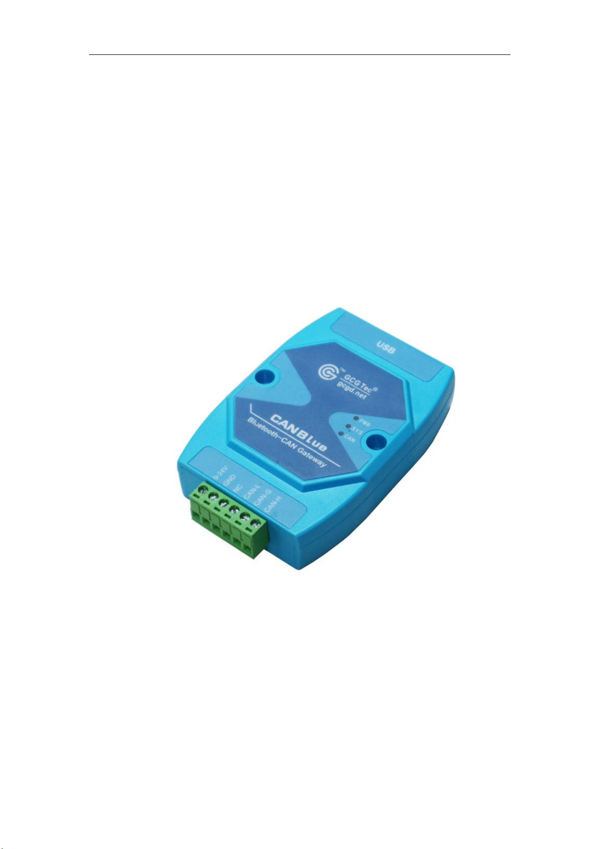
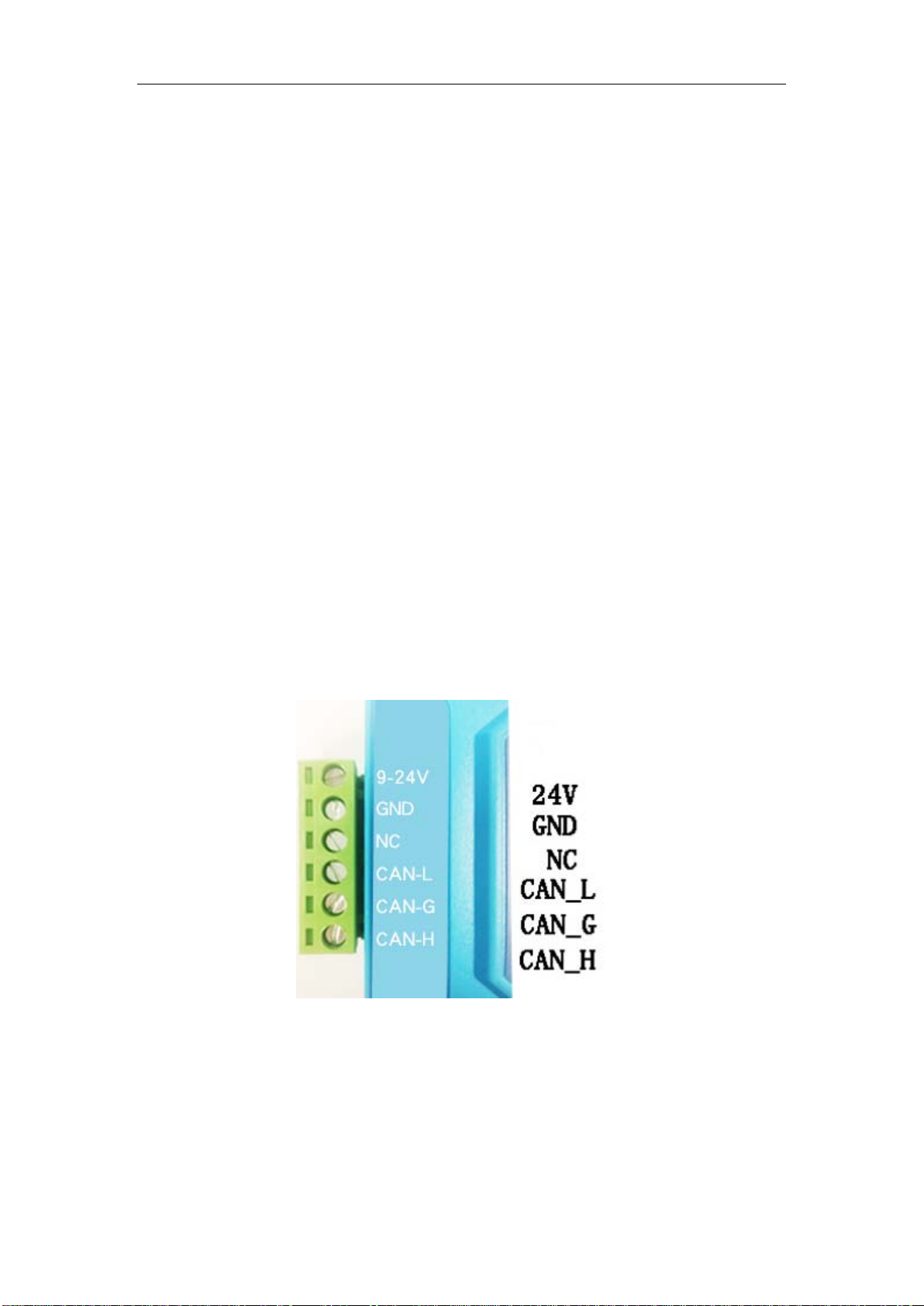
GCAN-203 interface shown in figure 2.1.
Figure 2.1 GCAN-203 interface definition
2.1 Power connection and indicator status
GCAN-203 recommends using standard 24V power supply. GCAN-203 has three
indicator lights, 1 PWR, 1 SYS, 1 CAN. The functions of the three indicators are
shown in table 2.2, the indicators in different states, the converter status shown in
table 2.3.
2
LED Color Indicates the status
PWR
Green
Power indicator
SYS Green Bluetooth connection
indication
CAN Red/Green CAN status indication
Table 2.2 GCAN-203 Indicators
LED Status Indicates the status
PWR On Power is normal
Off Power is not normal
SYS Blinking No equipment connected
Slow
blinking Equipment connection is
successful
CAN
Blinking
red CAN communication error
Blinking
green CAN communication is normal
Table 2.3 GCAN-203 indicator status
3. CANBlue config software
3.1 Configuration
Disconnect the GCAN-203 power supply. We can connect to GCAN-203 and
computer with USB. When GCAN-203 is configuring, no external power is required.
GCAN-203 factory setting: CAN-Bus baud is 250K, working mode is normal mode,
name is SN number, password is 1234.
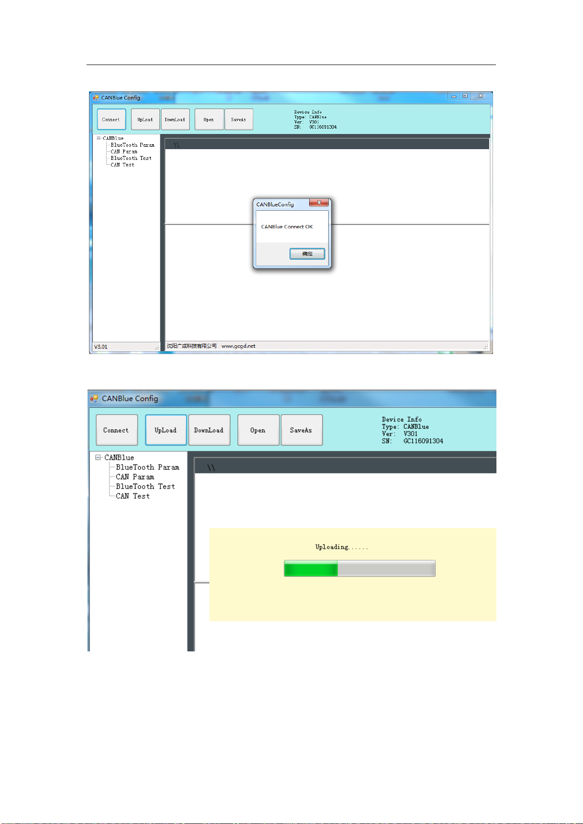
3.2 Software connection
Open "CANBlue Config" software in the "②CANBlue 模块配置软件" document to
configure the converter. Click "Connect" to connect the converter. The connection is
shown in figure 3.1.
You can click "UpLoad" to upload the parameters in the converter to your computer.
3
Figure 3.1 CANBlue Config software interface
Figure 3.2 CANBlue Config software upload parameters
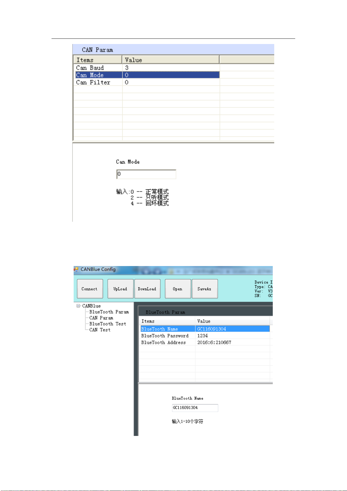
3.3 CAN parameter setting
Click "CAN Param" to enter CAN communication parameter setting. We can click
"CAN Baud" to configure the baud rate of the CAN-Bus, as shown in the following

4
table.
Parameter Baud rate Parameter Baud rate
0 1000K 1 800K
2 666K 3 500K
4 400K 5 250K
6 200K 7 125K
8 100K 9 80K
10
50K
11
40K
12 20K 13 10K
14 5K
Figure 3.3 CAN baud rate setting
The default value of “CAN Mode”or“CAN Filter”is set to 0, and please do not
change it.
5
Figure 3.4 CAN operating mode setting
3.4 Bluetooth parameter settings
Click "Bluetooth Param" to enter the Bluetooth parameter settings.
Figure 3.5 Bluetooth settings
6
The user can set the GCAN-203's name and connection password. GCAN-203's
default name is SN number, password is 1234.
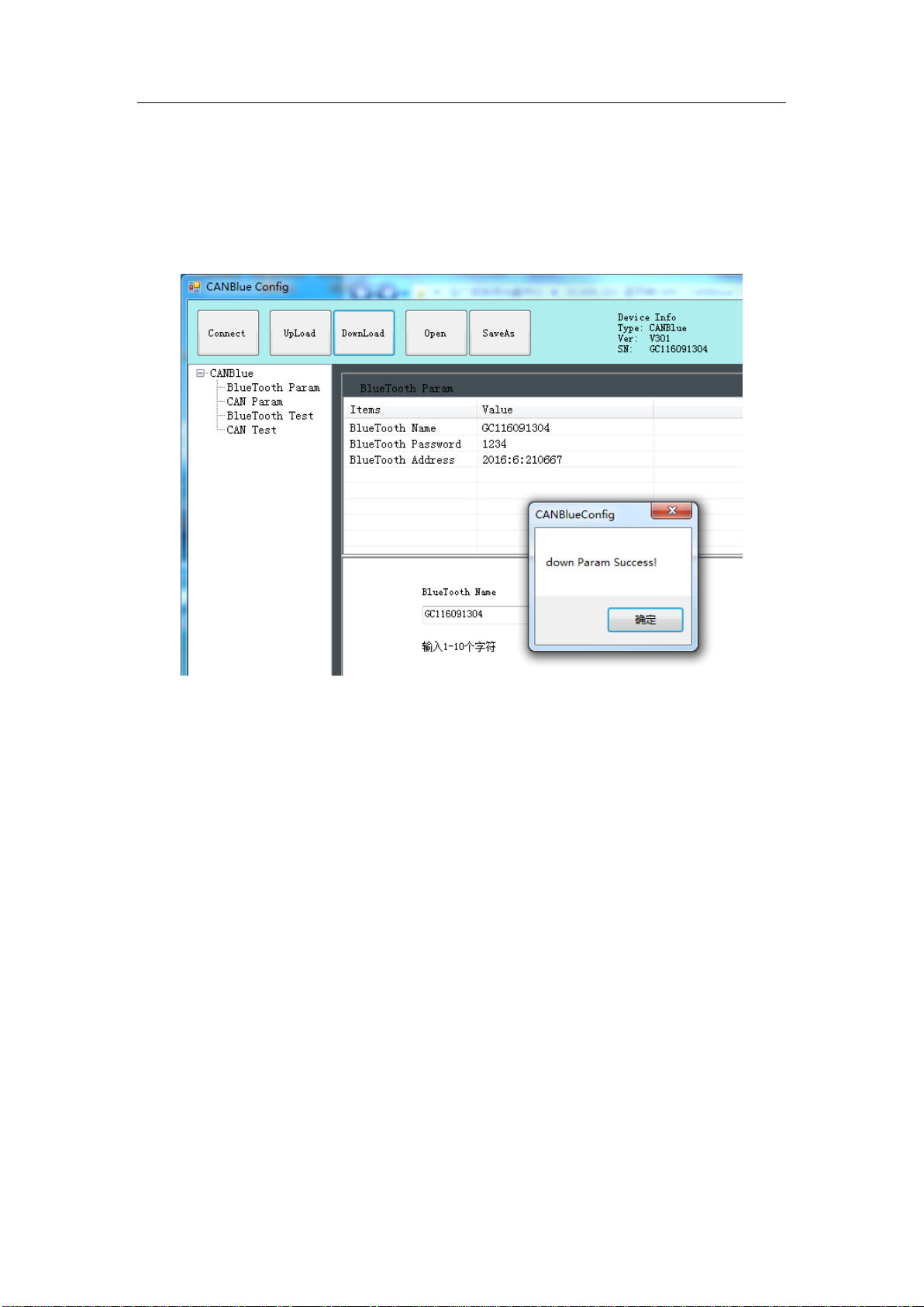
3.5 End of configuration
Click "Download" to write the configuration data to the converter's flash, as shown in
figure 3.6.
Figure 3.6 Download successful
The pop-up dialog displays "download Param success". Then power-on again. The
new configuration can take effect.
Note: The converter must be power-on again, otherwise the configuration will
not take effect.
3.6 Save the configuration file
Click “SaveAs” to save the configuration parameters to the PC. The file can be
opened again.
3.7 Open the configuration file
Use the “OPEN” function to open the configuration file and modify it. Then you can
click DownLoad to the converter that the new configuration can be saved.
Note: The working mode of “BlueTooth Test” and “CAN Test” is used for testing .
These functions cannot be used.
7
4. Application examples
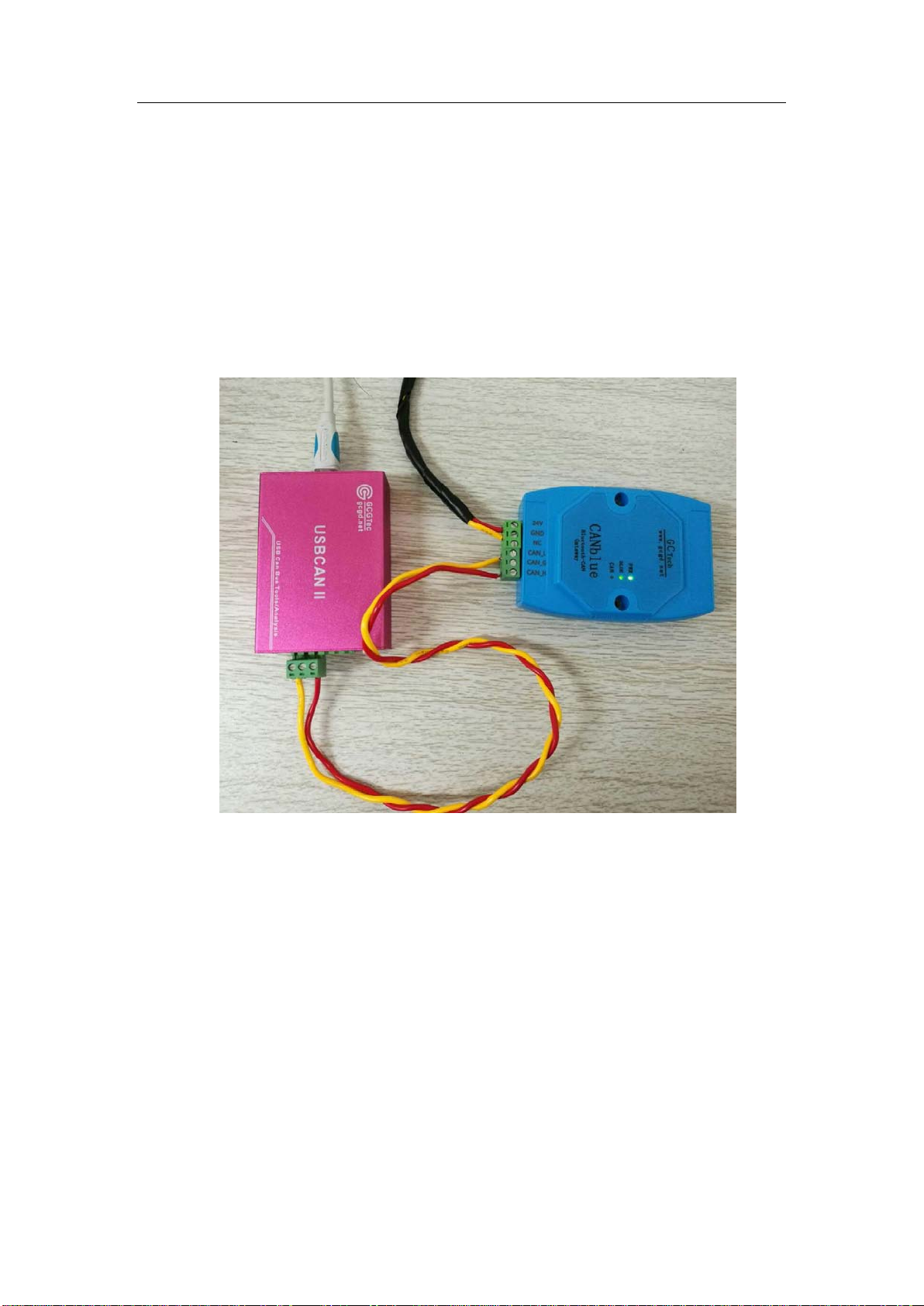
4.1 Equipment wiring
GCAN-203 uses 9-30V DC power supply.
Connect CAN_H to CAN-Bus CAN_H, CAN_L to CAN-Bus CAN_L. A High-speed
CAN bus must be terminated on both ends with 120 Ohms. Otherwise disturbances
may arise.
Figure 4.1 The wiring diagram of GCAN-203
As shown in figure 4.1, the left side of the equipment is USBCAN-II Pro. Wiring and
termination resistance must be confirmed correctly. Open USBCAN-II Pro equipment
with ECANtools software, then select the baud rate to 250K.
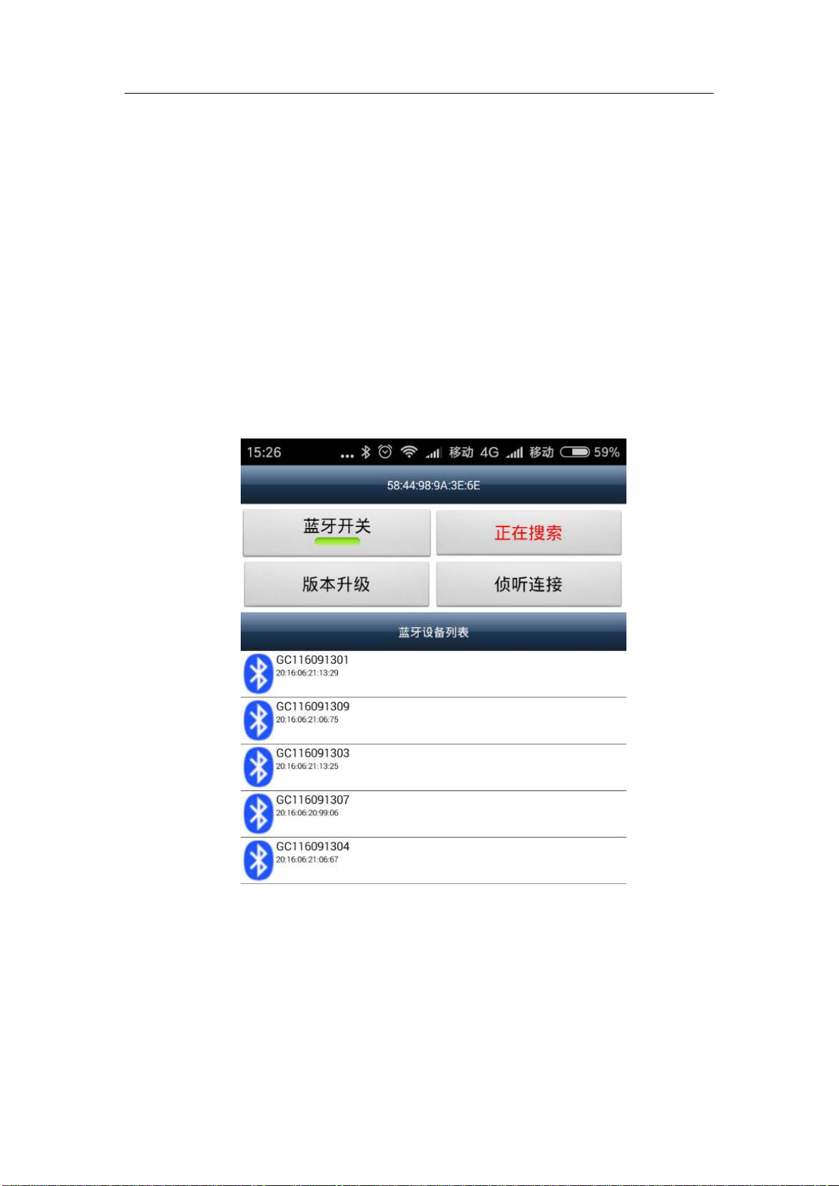
4.2 Bluetooth connection
Install "CANBlue.RSO.apk" APP to a mobile phone with android which is in the "③
安卓系统串口助手安装包" document. Search for Bluetooth equipment, then enter
the connection password.
8
4.3 Bluetooth serial assistant use
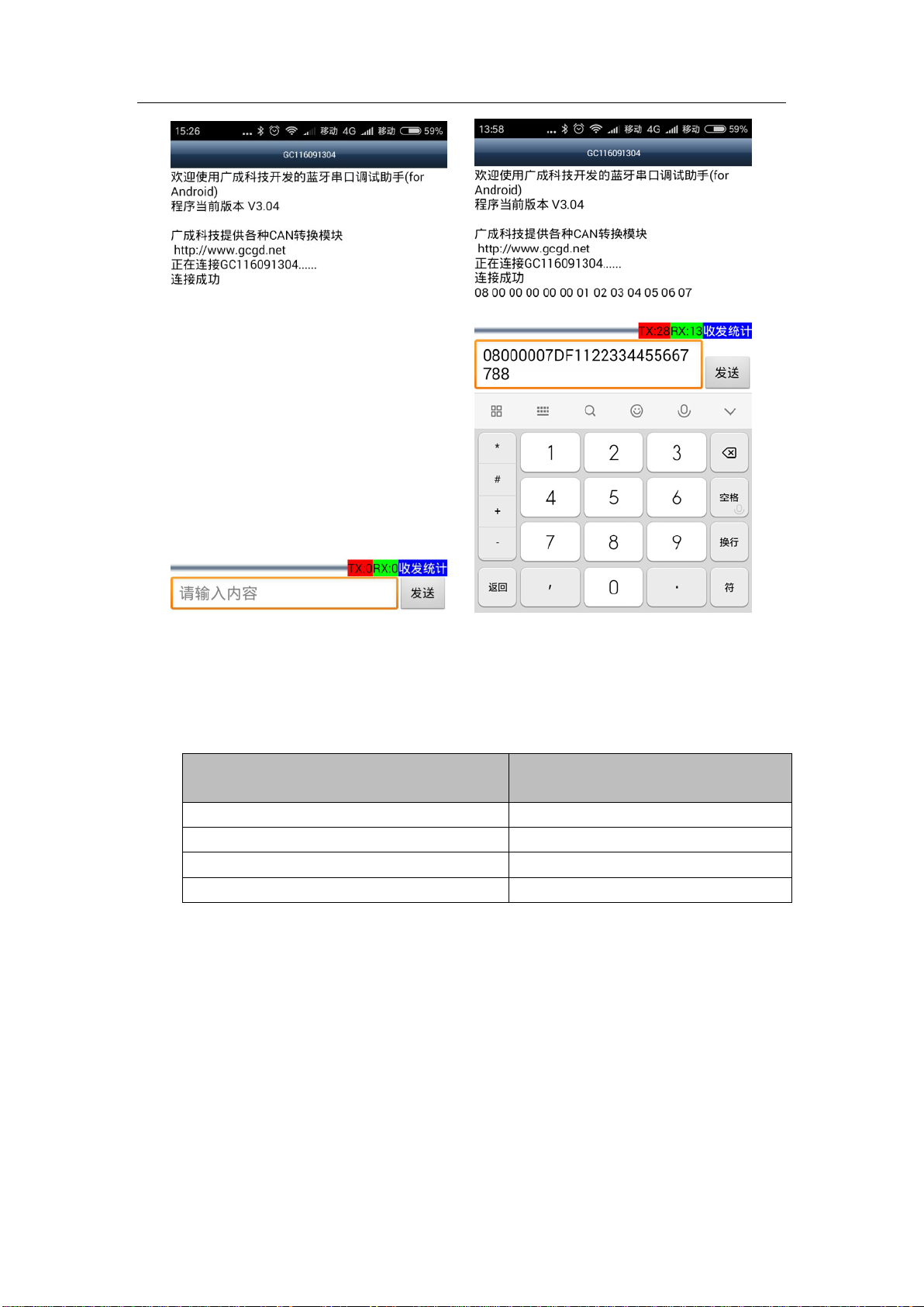
4.3.1 Connect to GCAN-203
Open the software, the interface is shown in figure 4.2. The function of the four
buttons will be shown here:
蓝牙开关——Turn on Bluetooth or turn off Bluetooth.
搜索设备——Click “搜索设备” .You can find all the converters that opened
Bluetooth, only the converter name turn blue can be connected. (GCAN-203's default
name is SN number, password is 1234)
版本升级——Not open yet.
侦听连接——Not open yet.
Enter the receive / send data interface, as shown in figure 4.3.
Figure 4.2 Software interface
9
Figure 4.3 Main interface for sending and receiving data
4.3.2 Send and receive data for example
The following is a brief introduction to the received / sent data format. Please refer to
the appendix for detailed data format.
Data description For example
CAN Frame Information(FF、RTR)0
CAN Frame Information(DLC)8
CAN Frame ID 00 00 07 00
CAN Frame Date 11 22 33 44 55 66 77 88
The CAN frame Information(FF, RTR) represents the frame format and frame type of
the CAN frame. The specific values are shown in the following table; the CAN frame
Information (DLC) represents the byte length of the CAN frame data. According to
the actual needs , it fills 0 to 8.
Example of special data transmission: table 4.1.
1.The mobile equipment sends data to the CAN terminal, DLC is 2 bytes less than 8
bytes of data(11 22 33 44 55 66 77 88), CAN receives 2 bytes of data (11 22).
2.The mobile equipment sends data to the CAN terminal, DLC is 8 bytes more than 4
bytes of data(11 22 33 44), CAN receives 8 bytes of data (11 22 33 44 XX XX XX

10
XX)(XX is used for the filling, which is meaningless).
3.CAN sends data to the mobile equipment, and CAN terminal sends 4 bytes of
standard data frame (11 22 33 44). The mobile equipment receives 8 bytes of frame
data (11 22 33 44 XX XX XX XX)(XX is used for the filling, which is meaningless).
Table 4.1 Example of special data transmission
Data transfer direction Data
1 The mobile equipment is sender 02 00 00 00 08 11 22 33 44 55 66 77 88
CAN is receiver Data length 2 bits, Frame ID: 008
Frame data: 11 22
2 The mobile equipment is sender 08 00 00 00 08 11 22 33 44
CAN is receiver Frame ID: 008
Frame data:11 22 33 44 XX XX XX XX
3 CAN is sender Data length 4 bits, frame ID: 008,
Frame data:11 22 33 44
The mobile equipment is receiver 04 00 00 00 08 11 22 33 44 XX XX XX
XX
11
5. Technical specifications
Connection
CAN interface Phoenix connector
Interface characteristics
CAN interface ISO 11898 standard, CAN2.0A/B
CAN baud rate 1000K, 500K, 250K, 200K, 125K, 100K, 50K
Electrical
isolation
1500V,DC-DC
CAN terminal
Need additional installation
Wireless parameters
Bluetooth Bluetooth 2.0
Power supply
Supply voltage +9~30V DC
Supply current 30mA
Environmental testing
Working
temperature -40℃~+85℃
Working
humidity
15% to 90% RH, no condensation
EMC test EN 55024:2011-09 EN 55022:2011-12
Protection
grade
IP 20
The basic information
Outline size 112mm *70mm *25mm
Weight 100g
12
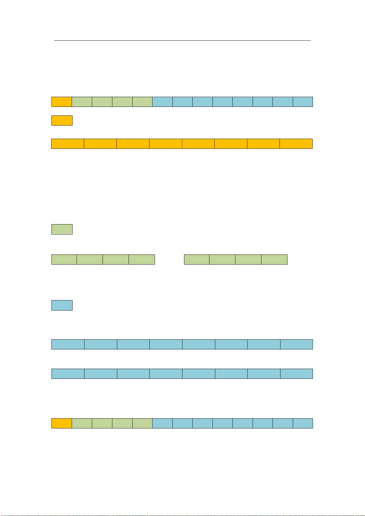
Appendix:GCAN-203 data flow definition
Bluetooth→CAN-bus data flow definition
A CAN frame contains 13 bytes.
CAN frame,For example, type or length of the CAN frame, and so on.
BIT7 BIT0
FF:Identifier for standard and extended frames, 1 means extended frame,0 means
Standard frame.
RTR:Remote frame and data frame identification bit, 1means extended frame,0
means Standard frame.
Reserve:Retention value is always 0.
B3~B0 :Data length. Identifying the data length of the CAN frame.
Frame ID. Its length is 4 bytes. Standard frame’s ID has 11 bits; extended
frame’s ID has 29bits.
High byte Low byte High byte Low byte
Representation of extended frame ID Representation of standard frame ID
0X12345678 0X123
Frame data. Its length is 8 bytes. The effective length is determined by the
B3~B0 value of the frame information.
DATA1 DATA8
11h 22h 33h 44h 55h 66h 77h 88h
The above is a typical representation of data, which has 8 bytes.
DATA1 DATA8
The above is a typical representation of data, which has 5 bytes.
Example:
The following example is an extended data frame, Frame ID is 0x12345678,
Contains 8 bytes of data.(11h,22h,33h,44h,55h,66h,77h,88h).
Note: each frame is fixed to 13 bytes. If it is less than 13, the empty parts will be
written with 0. Otherwise it will lead to communication error.
FF RTR Reserve Reserve B3 B2 B1 B0
12h 34h 56h 78h
00h
00h
01h
23h
11h 22h 33h 44h 55h 00h 00h 00h
88h 12h 34h 56h 78h 11h 22h 33h 44h 55h 66h 77h 88h

13
Sales and service
Shenyang Guangcheng Technology Co., Ltd.
Address: Industrial Design Center, No. 42 Chongshan
Middle Road, Huanggu District, Shenyang
City, Liaoning Province.
QQ: 2881884588
E-mail: [email protected]
Tel: +86-024-31230060
Website: www.gcgd.net
Sales and service Tel: +86-18309815706
After - sales service telephone Number: +86-13840170070
WeChat Number: 13840170070
Table of contents
Other GCAN Media Converter manuals


