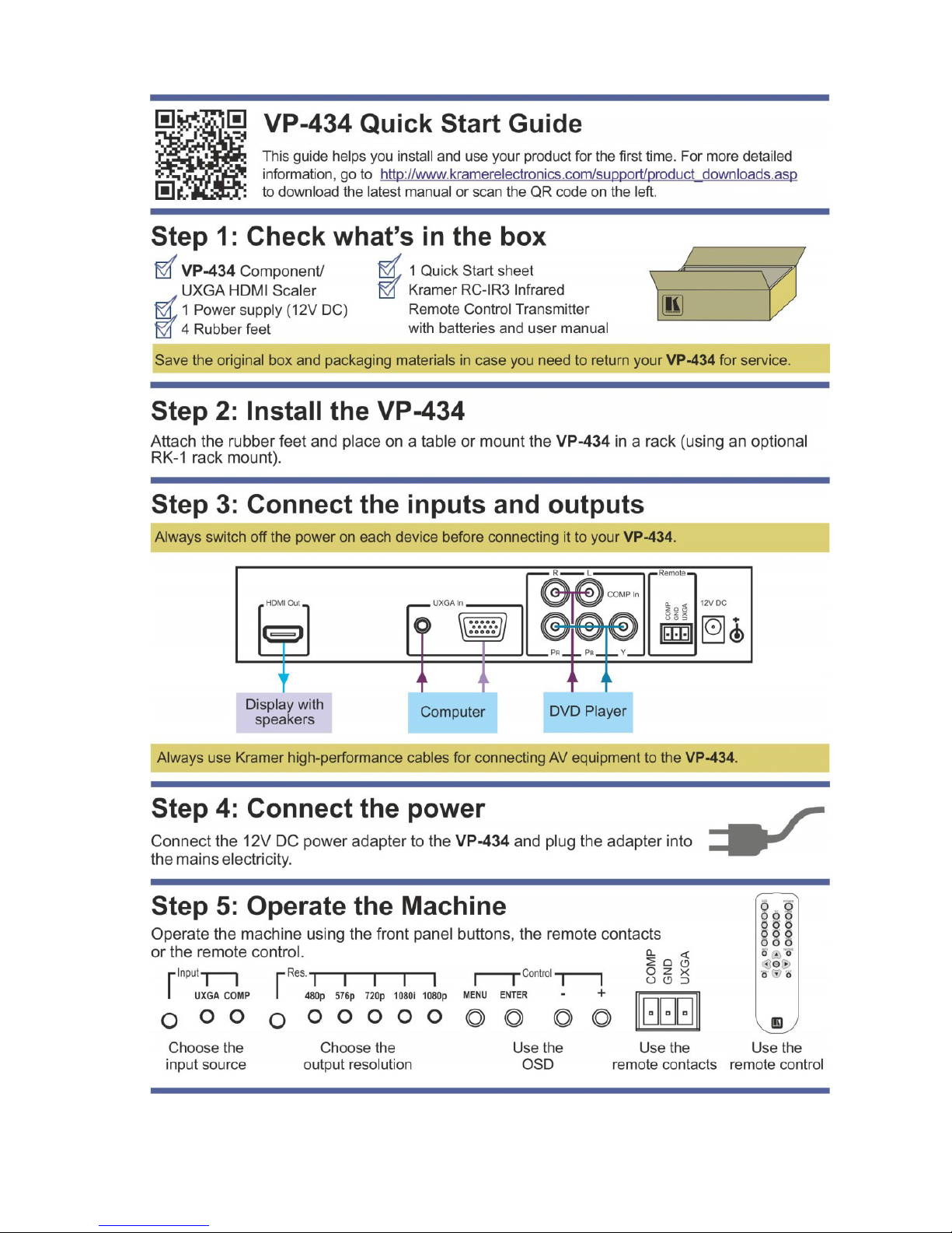
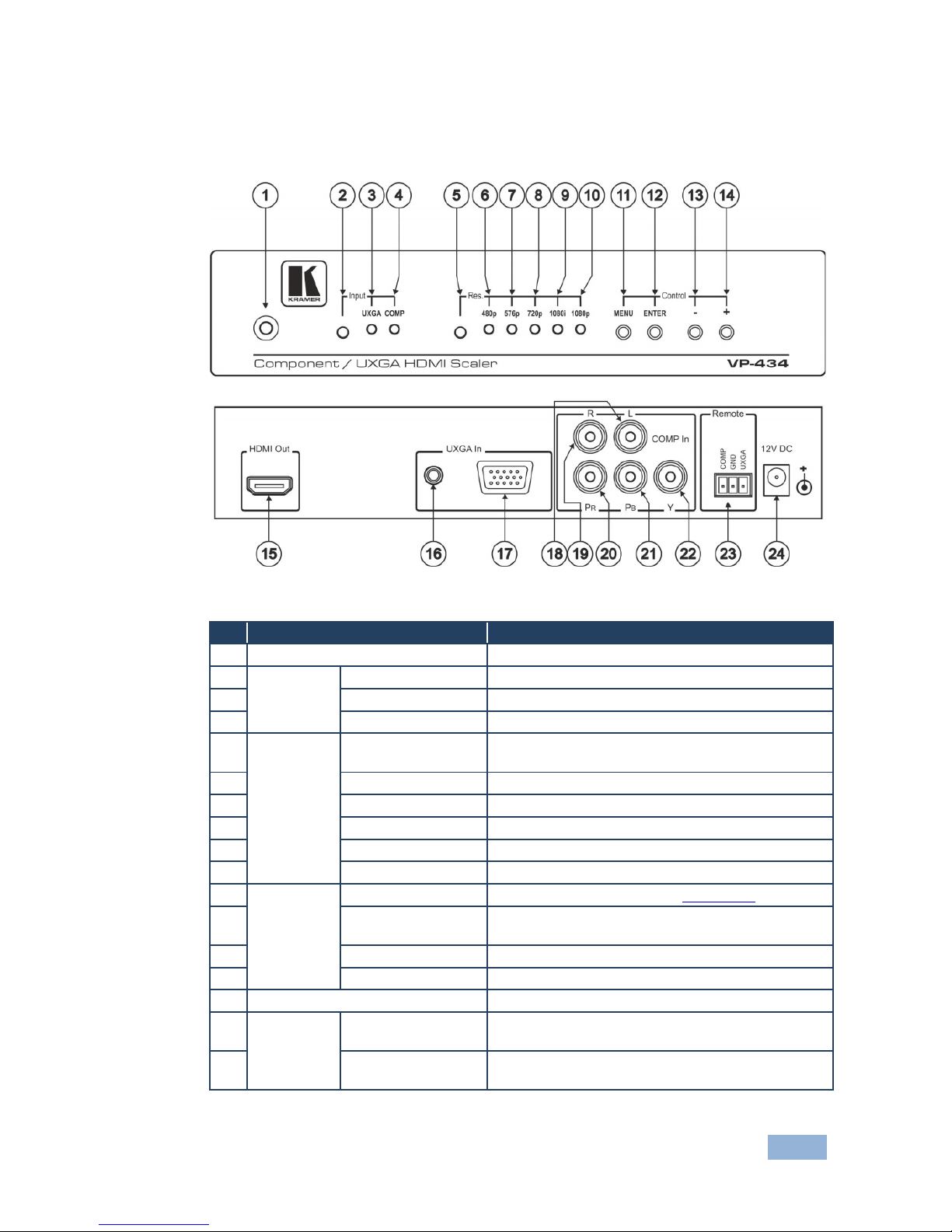
Kramer VP-434 User manual

KRAMER ELECTRONICS LTD.
USER MANUAL
MODEL:
VP-434
Component/UXGA HDMI Scaler
P/N: 2900-000346 Rev 6


VP-434 – Contents i
Contents
1Introduction 1
2Getting Started 2
2.1 Achieving the Best Performance 2
2.2 Safety Instructions 3
2.3 Recycling Kramer Products 3
3Overview 4
3.1 Defining the VP-434 Component/UXGA HDMI Scaler 5
4Connecting the VP-434 7
4.1 Connecting the Contact Closure Remote Control PINs 9
5Operating the VP-434 10
5.1 Using the Front Panel Buttons 10
5.2 Using the CONTROL Buttons 10
5.3 Using the Infrared Remote Control Transmitter 12
6Technical Specifications 13
Figures
UFigure 1: VP-434 Component/UXGA HDMI ScalerU5
UFigure 2: Connecting the VP-434 Component/UXGA HDMI ScalerU8
UFigure 3: Connecting the Contact Closure Remote Control PINsU9
UFigure 4: Infrared Remote Control TransmitterU12

VP-434 - Introduction 1
1 Introduction
Welcome to Kramer Electronics! Since 1981, Kramer Electronics has been
providing a world of unique, creative, and affordable solutions to the vast range of
problems that confront video, audio, presentation, and broadcasting professionals
on a daily basis. In recent years, we have redesigned and upgraded most of our
line, making the best even better!
Our 1,000-plus different models now appear in 11 groups that are clearly defined
by function: GROUP 1: Distribution Amplifiers; GROUP 2: Switchers and Routers;
GROUP 3: Control Systems; GROUP 4: Format/Standards Converters; GROUP 5:
Range Extenders and Repeaters; GROUP 6: Specialty AV Products; GROUP 7:
Scan Converters and Scalers; GROUP 8: Cables and Connectors; GROUP 9:
Room Connectivity; GROUP 10: Accessories and Rack Adapters and GROUP 11:
Sierra Products.
Congratulations on purchasing your Kramer VP-434 Component/UXGA HDMI
Scaler, which is ideal for the following typical applications:
•Projection systems in conference rooms, boardrooms, auditoriums, hotels
and churches, production studios, rental and staging
•Home theater up-scaling

2 VP-434 - Getting Started
2 Getting Started
We recommend that you:
•Unpack the equipment carefully and save the original box and packaging
materials for possible future shipment
•Review the contents of this user manual
Go to http://www.kramerelectronics.com to check for up-to-date
user manuals, application programs, and to check if firmware
upgrades are available (where appropriate).
2.1 Achieving the Best Performance
To achieve the best performance:
•Use only good quality connection cables (we recommend Kramer high-
performance, high-resolution cables) to avoid interference, deterioration in
signal quality due to poor matching, and elevated noise levels (often
associated with low quality cables)
•Do not secure the cables in tight bundles or roll the slack into tight coils
•Avoid interference from neighboring electrical appliances that may adversely
influence signal quality
•Position your Kramer VP-434 away from moisture, excessive sunlight and
dust
This equipment is to be used only inside a building. It may only be
connected to other equipment that is installed inside a building.
i
!

VP-434 - Getting Started 3
2.2 Safety Instructions
Caution: There are no operator serviceable parts inside the unit
Warning: Use only the Kramer Electronics input power wall
adapter that is provided with the unit
Warning: Disconnect the power and unplug the unit from the wall
before installing
2.3 Recycling Kramer Products
The Waste Electrical and Electronic Equipment (WEEE) Directive 2002/96/EC
aims to reduce the amount of WEEE sent for disposal to landfill or incineration by
requiring it to be collected and recycled. To comply with the WEEE Directive,
Kramer Electronics has made arrangements with the European Advanced
Recycling Network (EARN) and will cover any costs of treatment, recycling and
recovery of waste Kramer Electronics branded equipment on arrival at the EARN
facility. For details of Kramer’s recycling arrangements in your particular country
go to our recycling pages at http://www.kramerelectronics.com/support/recycling/.
!

4 VP-434 - Overview
3 Overview
The Kramer VP-434 is a high-quality component video/UXGA (computer video
graphics) to HDMI scaler. It accepts one of two inputs: either component video (Y,
Pb, Pr, Y, Cb, Cr and YUV; compatible with both SD and HD component) on RCA
connectors or computer video graphics on a 15-pin HD computer graphics video
connector (selected via a front panel selector button or via the remote contact
closure switch). It scales the video, embeds the audio, and outputs the signal to
the HDMI output.
The VP-434 Component / UXGA HDMI Scaler:
•Is HDTV compatible and the resolution can be scaled up to 480p, 576p,
720p, 1080i or 1080p via a front panel selector button
Select other resolutions from the OSD menu including: 1080i, 1080p, 576i, 576p, 720p,
1080i, 1080p, WXGA, WSXGA, WUXGA, NATIVE, VGA, SVGA, XGA, SXGA, UXGA,
480i, 480p.
•Has analog audio inputs for the COMP and UXGA sources
•Comes with an On-Screen Display (OSD) for easy setup and adjustment,
accessible via the IR remote control and via the front-panel buttons
•Has a non-volatile memory that retains the last settings used
•Is housed in a desktop sized enclosure and is 12VDC fed
Control your VP-434:
•Directly, via the front panel push buttons
•Remotely, from the infrared remote control transmitter
•Remotely, from the remote contact closure switch

VP-434 - Overview 5
3.1 Defining the VP-434 Component/UXGA HDMI Scaler
This section defines the VP-434.
Figure 1: VP-434 Component/UXGA HDMI Scaler
# Feature Function
1 IR Receiver Receives signals from the remote control transmitter
2 INPUT Selector Button Press to select the UXGA input or the COMP input
3 UXGA Indicator LED Lights when the UXGA input is selected
4 COMP Indicator LED Lights when the COMP input is selected
5 RES. Selector Button Press to select the resolution: 480p, 576p, 720p,
1080i or 1080p
6 480p Indicator LED Lights when the 480p resolution is selected
7 576p Indicator LED Lights when the 576p resolution is selected
8 720p Indicator LED Lights when the 720p resolution is selected
9 1080i Indicator LED Lights when the 1080i resolution is selected
10 1080p Indicator LED Lights when the 1080p resolution is selected
11 CONTROL MENU Button Displays the OSD menu (see Section 5.2
12
)
ENTER Button Press to accept changes and change the SETUP
parameters
13 - Button Press to move down the menu list
14 + Button Press to move up the menu list values
15 HDMI Out Connector Connects to the HDMI acceptor
16 UXGA In 3.5mm Mini Jack
Connector
Connects to the analog unbalanced stereo audio
signal source
17 UXGA 15-pin HD
Connector
Connects to the UXGA source

6 VP-434 - Overview
# Feature Function
18 COMP In L RCA Connector Connect to the left and right analog unbalanced
stereo audio source (of the COMP source)
19 R RCA Connector
20 PRRCA Connector Connects to the component video source
For component video, connect all three connectors:
Y, Cb, Cr (also known as YUV)
21 PBRCA Connector
22 YRCA Connector
23 Remote Contact Closure Pins Connects to a contact closure switch (see Section
4.1
24
)
12V DC +12V DC connector for powering the unit

VP-434 - Connecting the VP-434 7
4 Connecting the VP-434
Always switch off the power to each device before connecting it to your
VP-434. After connecting your VP-434, connect its power and then
switch on the power to each device.
To connect the VP-434 as illustrated in the example in Figure 2:
1. Connect a component video source (for example, a DVD player) to the
COMP In Y, Pb, Pr, RCA connectors, and to the COMP In L and R audio
RCA connectors.
2. Connect a computer graphics source to the UXGA In 15-pin HD computer
graphics video connector, and to the UXGA In audio 3.5mm mini jack
connector.
3. Connect the HDMI Out connector to an HDMI acceptor (for example, a
plasma display).
4. Connect the 12V DC power adapter to the power socket and connect the
adapter to the mains electricity (not shown in Figure 2).
i

8 VP-434 - Connecting the VP-434
Figure 2: Connecting the VP-434 Component/UXGA HDMI Scaler

VP-434 - Connecting the VP-434 9
4.1 Connecting the Contact Closure Remote Control PINs
The contact closure pins operate in a similar way to the Input selector button.
Using the contact closure remote control you can select the COMP or the UXGA
input. To do so, temporarily connect the required input (COMP or UXGA) pin on
the REMOTE terminal block connector to the GND (ground) pin, as illustrated in
Figure 3
.
DO NOT connect more than one PIN to the GND PIN at the same
time
Figure 3: Connecting the Contact Closure Remote Control PINs
!
To select COMP,
connect the
COMP PIN to the
GND PIN
To select UXGA,
connect the
UXGA PIN to the
GND PIN

10 VP-434 - Operating the VP-434
5 Operating the VP-434
The VP-434 can be controlled directly via the front panel buttons (see Section 5.1),
via the OSD menu (see 5.2Section ), and/or remotely from the infrared remote
control transmitter (see 5.3Section
5.1 Using the Front Panel Buttons
).
The VP-434 includes the following front panel buttons:
•An Input selector button for selecting the required input (UXGA or COMP)
•A resolution (Res.) button for selecting the desired resolution
•Control buttons, including the MENU, ENTER, + and – buttons
5.2 Using the CONTROL Buttons
The CONTROL buttons let you control the VP-434 via the OSD menu. Press the:
•MENU button to enter the menu
The default timeout is set to 10 seconds
•ENTER button to accept changes and to change the menu settings
•+ and – buttons to move through the OSD menu, which is displayed on the
video output
On the OSD menu, select EXIT to exit the menu.

VP-434 - Operating the VP-434 11
5.2.1 The MAIN MENU
The following table defines the MAIN MENU features and functions.
Mode
Function
CONTRAST Set the contrast (0 to 100)
BRIGHTNESS Set the brightness (0 to 100)
FINETUNE Set the hue, saturation and sharpness (0 to 100)
COLOR Set the red, green and blue shades (0 to 100)
SIZE Select the size of the display: full, overscan, underscan, letter box, panscan
OUTPUT Select the output resolution from the menu:
Appears as: Output resolution: Appears as: Output resolution:
1080I60 1080i @60Hz NATIVE
Select “NATIVE”
to select the
output resolution
from the EDID of
the connected
HDMI monitor
1080P60 1080p @60Hz VGA 640x480
576I 576i SVGA 800x600
576P 576p XGA 1024x768
720P50 720p @50Hz SXGA 1280x1024
1080I50 1080i @50Hz UXGA 1600x1200
1080P50 1080p @50Hz 480I 480i
WXGA 1280x720 480P 480p
WSXGA 1680x1050 720P60 720p @50Hz
WUXGA 1920x1200
OSD Set the OSD parameters: H POSITION, V POSITION, TIMER,
BACKGROUND (see Section 5.2.2
FACTORY
RESET
)
Resets to the default parameters (resolution is set to VGA)
If you cannot see the display after factory reset, use the front panel Res. button to
set the correct resolution
INFORMATION Displays the source, the input resolution, the output resolution and the
software version
EXIT Select to exit the menu
5.2.2 The OSD Menu
The following table defines the OSD menu.
Parameter Function
H POSITION Sets the horizontal position of the OSD (from 0 to 100)
V POSITION Sets the vertical position of the OSD (from 0 to 100)
TIMER Sets the timeout period in seconds (from 5 to 100). The default timeout is 10
seconds
BACKGROUND Sets the OSD background between 0 (solid black) and 8 (transparent)

12 VP-434 - Operating the VP-434
5.3 Using the Infrared Remote Control Transmitter
You can control the VP-434 from the infrared remote control transmitter, as
defined in Figure :4
Figure 4: Infrared Remote Control
Transmitter
Keys Function
SIZE Set the size of the image displayed
POWER Turn the unit VP-434 ON or OFF
OFF in this case means that the
outputs and the front panel are
disabled
HD Select the component video input
PC Select the UXGA input
HDMI Not used
VGA Set the output resolution to VGA
SVGA Set the output resolution to SVGA
XGA Set the output resolution to XGA
SXGA Set the output resolution to SXGA
UXGA Set the output resolution to UXGA
1080i Set the output resolution to 1080i
480p Set the output resolution to 480p
720p Set the output resolution to 720p
1080p Set the output resolution to 1080p
INFO Displays the selected input, the input
and output resolutions and the
firmware versions on the OSD
NATIVE Select the output resolution from the
EDID of the connected HDMI
monitor
Four navigation keys
OK Press to accept changes
MENU Enter the OSD menu
EXIT EXIT the menu
POWER
SIZE
HD PC HDMI
VGA SVGA XGA
SXGA UXGA
1080i
1080p480p 720p
NATIVE
EXIT
INFO
MENU
OK

VP-434 - Technical Specifications 13
6 Technical Specifications
INPUTS: 1 UXGA on a 15-pin HD connector
1 component video on 3 RCA connectors
1 analog unbalanced stereo audio on a 3.5mini jack
connector (for the UXGA input)
2 analog unbalanced stereo audio (left and right) on RCA
connectors, 4dBm nominal
OUTPUT: 1 HDMI connector
OUTPUT RESOLUTIONS: 1080i, 1080p, 576i, 576p, 720p, 1080i, 1080p, WXGA,
WSXGA, WUXGA, NATIVE, VGA, SVGA, XGA, SXGA,
UXGA, 480i, 480p
OUTPUT REFRESH RATE: 60Hz for computer graphics resolutions, 50/60Hz for
HDTV resolutions
CONTROLS: Front panel buttons, contact closure and infrared remote
for menu driven OSD control
ADDITIONAL CONTROLS: Contrast, brightness, hue, saturation and sharpness; red,
green and blue; Resolution, image size
POWER CONSUMPTION: 12V DC, 800mA
OPERATING TEMPERATURE: 0° to +40°C (32° to 104°F)
STORAGE TEMPERATURE: -40° to +70°C (-40° to 158°F)
HUMIDITY: 10% to 90%, RHL non-condensing
DIMENSIONS: 21.5cm x 16.1cm x 4.36cm (8.46” x 6.34” x 1.7”) W, D, H
WEIGHT: 1.1kg (2.43lb) approx.
ACCESSORIES: Power supply, IR remote control
OPTIONS: RK-1 Rack adapter
Specifications are subject to change without notice at http://www.kramerelectronics.com

14 VP-434 - Technical Specifications

For the latest information on our products and a list of Kramer distributors,
visit our Web site where updates to this user manual may be found.
We welcome your questions, comments, and feedback.
Web site:
E-mail:
www.kramerelectronics.com
info@kramerel.com
P/N:
2900- 000346
Rev:
6
!
SAFETY WARNING
Disconnect the unit from the power
supply before opening and servicing
Other manuals for VP-434
1
Table of contents
Other Kramer Media Converter manuals

Kramer
Kramer FC-10 User manual

Kramer
Kramer DigiTOOLS 7408 User manual

Kramer
Kramer ACC3-12-SP User manual

Kramer
Kramer TOOLS FC-47 User manual

Kramer
Kramer VM-28H User manual

Kramer
Kramer PIP-400 User manual

Kramer
Kramer VM-80VN User manual

Kramer
Kramer KDS-10 User manual

Kramer
Kramer TP-580TD User manual

Kramer
Kramer VP-501N User manual

Kramer
Kramer VM-2Hxl User manual

Kramer
Kramer FC-113 User manual

Kramer
Kramer PIP-200XL User manual

Kramer
Kramer KDS-EN6 User manual

Kramer
Kramer VP-420 User manual

Kramer
Kramer VM-80VN User manual

Kramer
Kramer FC-7501 User manual

Kramer
Kramer VP-2K User manual

Kramer
Kramer VP-721DS User manual

Kramer
Kramer VP-424 User manual