GCOM Systems EV486ACT User manual

Owner’s Manual EV486ACT
Replacement Mirror Monitor System
with Auto-Dimming & Temperature & Compass
V1.0

WARNINGS
THE FOLLOWING INSTRUCTIONS ARE INTENDED FOR AUTHORIZED
GCOM SYSTEMS INSTALLERS ONLY.
PROFESSIONAL INSTALLATION BY AUTHORIZED GCOM RETAILER
REQUIRED TO BE COVERED UNDER WARRANTY.
Dropping your EV486ACT unit or subjecting it to excessive shock and vibrations
as this may cause it to malfunction and is not covered by warranty.
The EV486ACT unit IS NOT WATERPROOF. Avoid exposing it to rain or other
forms of excessive moisture. Water damage is not covered under the
warranty.
1. Wiring
RED- Accessory
Black- Chassis Ground
Green- Not Used as Video On/Off Switching is Trigger by Video Signal Voltage
Temp. Sensor 1-Interior Temperature Sensor (8 feet)
Temp. Sensor 2-Exterior Temperature Sensor (14 feet)
VIDEO Camera RCA- Video input for camera (priority). The circuit switches
automatically when video is sensed by powering up the reverse camera
VIDEO IN RCA- AUX Video input (DVD, MP4 etc.) This circuit is secondary and so it will
be over written when Camera video is sensed.
Reassemble all above covers and make connections at knee bolster.
1) Connect the camera’s 12V and GND wire to reverse tail lamp.
2) Connect the camera’s RCA to the mirror’s Camera input
3) Connect the EV486ACT 12V+ wire to the vehicle’s ACC wire.
4) Connect the EV486ACT ground wire (BLACK) to chassis GND
2. Installation
1) Remove existing mirror from vehicle.
2) If existing mirror tab is D-tab style mount EV486ACT mirror to windshield and
go to step 3. If original mirror is not D-tab style or headliner mount go to step
2a.
2a) Locate the supplied D-tab and the rearview mirror adhesive and install on
windshield as per adhesive instructions.
Note: DO NOT ATTEMPT TO REMOVE THE EXISTING TAB AS DAMAGE TO THE
WINDSHIELD MAY OCCUR
3) Remove the knee bolster on the driver side as well as the A-pillar cover (it may
1
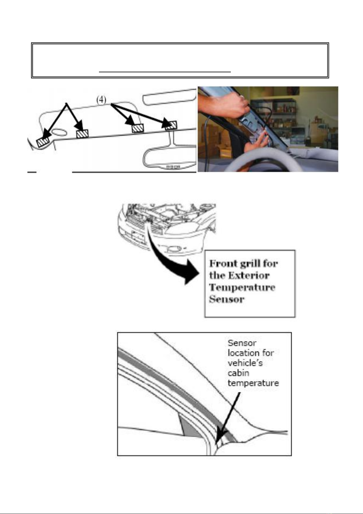
also be necessary to remove the sun visor and maybe even the overhead
console in order to freely route the power harness from the knee bolster to the
mirror connector).
4) Install the Exterior Temperature Sensor at Front grill (away from the Engine heat)
5) Install the Interior Temperature Sensor (away from the A/C ventilation) A pillar
6) Install the mirror and connect the power harness to the mirror and use supplied
mirror harness wire cover in order to neatly route the cable up the windshield to
the headliner.
Important!
Make sure to route the wire behind the airbag for safety precaution.
2

3. Setup
1) Turn Ignition ON
2) If AUX video 1 source is connected (turn video source ON then press PWR
button on mirror and the image should appear on screen)
3) Shift vehicle into reverse, the camera image will appear on the screen
4) Shift vehicle out of reverse and the camera image will disappear and go back to
its previous stage
5) The white window on the right side of the power button is the photo sensor to
activate the monitor self-dimming/auto-brightness.
6) Press the key for 3 seconds to change the display.
The mirror has 4 Compass/Temperature display options
-1) Display Temperature 1
-2) Display Temperature 2 (Display is flashing)
-3) Display Compass
-4) Display Temperature 2, Temperature 1 & Compass
Display Description
Display
N
NE
E
SE
S
SW
W
NW
Meaning
North
North
East
East
South
East
South
South
West
West
North
West
OC
OF
CF
H-
A-
ER
OK
Celsius
Fahrenheit
C/F
SET
Magnetic
Variation
Set
Auto
Calibratio
n
Error
Display
Right
Display
Calibration Description
Key operation description
Quick Press :Press key less than 1 second
Hold :Hold key for 3 second to 6 second (display flash one time)
Long Hold : Hold key for more than 6 second (display flash two time)
Hold for 3 seconds to switch display (Temp 1, 2 & Compass)
Display Calibration
Celsius/Fahrenheit Settings
Hold for 6 seconds to enter Settings
Select C (Celsius) or F (Fahrenheit) by pressing the once.
Hold for 3 seconds to save and enter to Compass Settings
Manual Compass Calibration “H-”
3
Press once to adjust Compass (﹣25° ~﹢25°)
Find out the magnetic declination of the certain area.
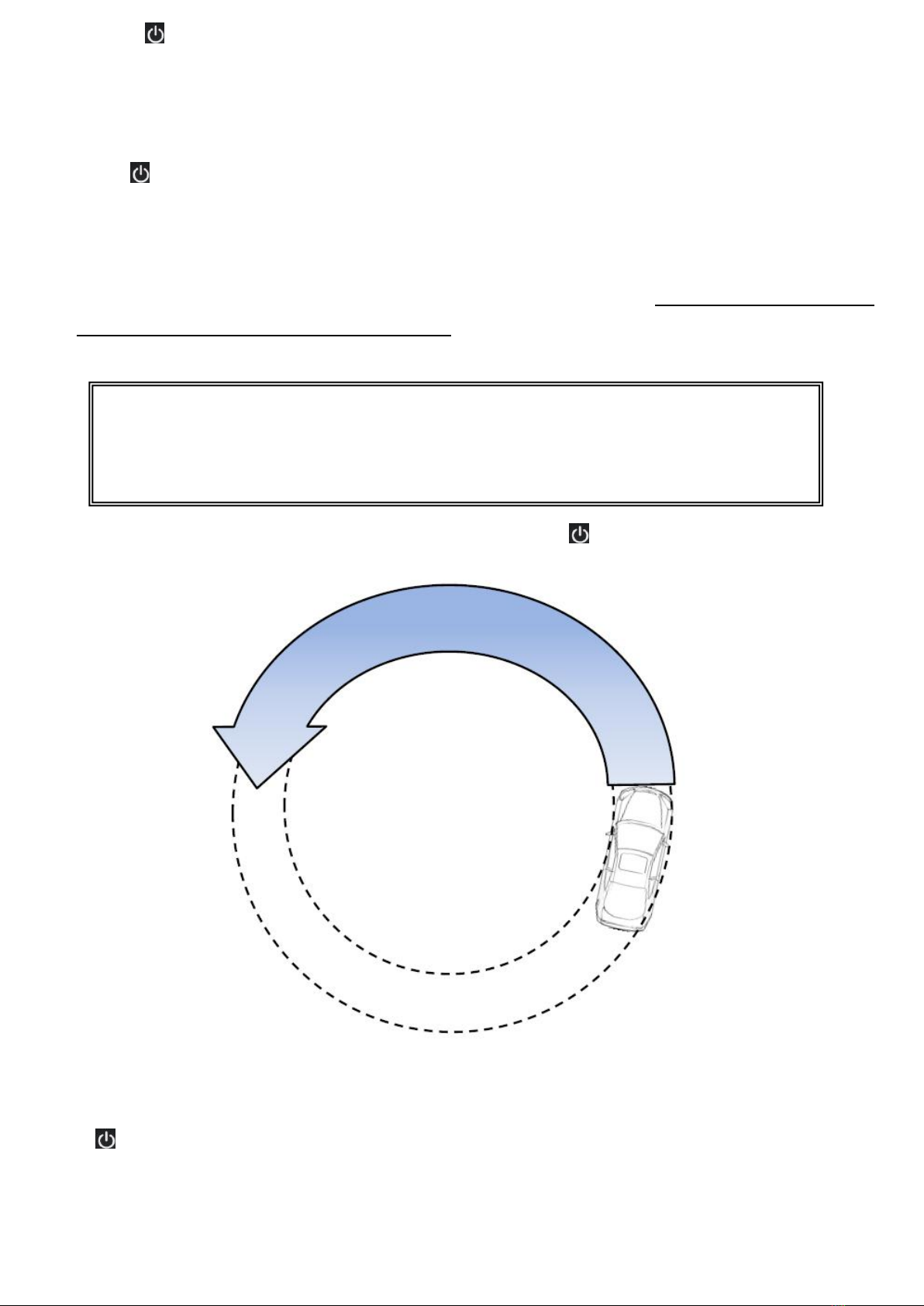
Automatic Compass Calibration “A-“
Hold for 3 seconds to save the previous setting then enters the Automatic Compass
Calibration “A-“.
The mirror will start counting from 0-200
Starting from 20 seconds, put the vehicle in drive and drive the vehicle less
than 5MPH going counter clockwise.
After 2 laps of counter clockwise, press and hold for 3 seconds to enter
setup.
After calibrating the compass, you may exit the settings mode and test the
mirror’s compass and temperature.
If button is pressed for 1 second, it is considered as invalid and the mirror
will display “ER” as error.
Important!
Performing this calibration process require a clear area to drive the
vehicle in circles to calibrate the compass properly.
4
4. Power Button Operation
Press and Hold Key for 3 seconds to switch display (Temp2, Temp1,
Compass or Temp2, Temp1 Compass cycle)
Press once to turn ON/OFF temperature/compass display
Press and Hold key for 6 seconds to enter settings
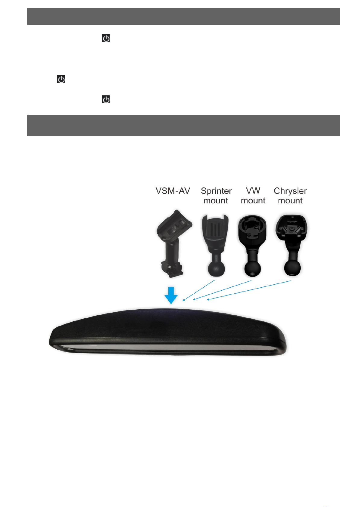
5. Removable Mount Structure
EV486ACT is equipped with the removable mounting stem
structure, which allows to exchange with the following available
ball joint mounting stems.
5

6. Trouble Shooting
Q: The Green LED never turns ON and I do not get a picture?
A: Test to confirm that (+ & -) are connected properly and fuse is good.
Q: The Green LED is ON but I do not see any picture?
A: Make sure that the video RCA’s are connected properly and that the camera is
powered up properly as per camera instructions.
Q: The Green LED is always ON?
A: It’s a light indicator to show the mirror is receiving voltage.
Q: The image on the mirror is opposite (left is right and right is left) what is wrong?
A: The White jumper on the camera harness is connected (should be cut in half).
Q: I do NOT like the parking lines, how can I turn them OFF?
A: Connect the Green jumper at the camera harness to turn the parking line feature
OFF.
7. Technical Support Contact Info
If you have other questions about the GCOM EV486ACT, please contact your retailer
or Technical Support:
Telephone: 1-877-777-8811 (within USA only)
Web Address: www.gcomsystems.com
6

www.gcomsystems.com
Rydeen North America Inc.
2701 Plaza Del Amo, Suite 705, Torrance, California 90503 USA
Phone: 1-877-777-8811 Fax: 1-310-943-3778
Copyright © 2013 Rydeen North America Inc. All Rights Reserved.
These materials are protected by copyright law and international treaties. Any unauthorized use, reproduction or distribution of these materials, or any portion
herein, will result in severe civil and criminal penalties and fines. Violators will be prosecuted to the fullest extent of the law.
Table of contents
Other GCOM Systems Automobile Accessories manuals


