Quickstart Guide
C2 Protector Controller with Remote
GASMAX II Gas Monitor
GASMAX II POWER SUPPLY
ASSEMBLY BOARD
P/N #10-0233
AUTHORIZED DISTRIBUTOR - GasDetectorsUSA.com - Houston, Texas USA
sales@GasDetectorsUSA.com
Ground Shield at C2
Controller (Recommended)
Important:
The GASMAX II output is
polarized. Take care in
connecting the +24VDC
source, 4-20mA output and
ground reference wiring.
S2
Ribbon to Display
1 2 4 3
PWR
OUT 4-20
“ECHEM”
OUT 4-20
“LEL”
GND
REF
COM
ACT
CATBEAD
S1
C7 C8
C1 C2
I/O Power Supply
Assy 10-0233
TB1 TB2
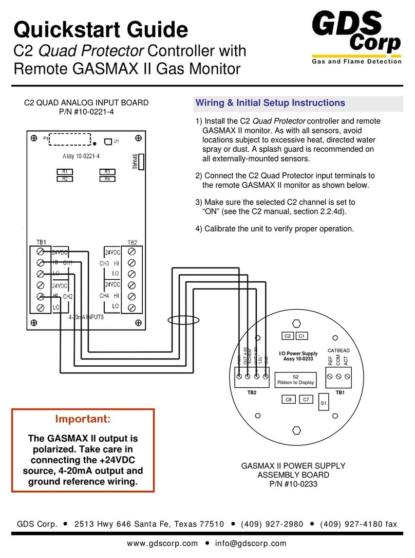
As shown, GASMAX II ECHEM 4-20mA output is connected to
C2 channel 2 and GASMAX II LEL 4-20mA output is connected
to C2 channel 1.
TB2
R1
R2
TB1
4-20mA INPUTS
CH2
+24VDC POWER OUT
(For Xmtrs.requiring
24VDC; see manual)
CH1
1 2 3 41 2
C2 ANALOG INPUT BOARD
P/N #10-0221
Wiring & Initial Setup Instructions
1) Install the C2 Protector controller and remote GASMAX
II monitor. As with all sensors, avoid locations subject to
excessive heat, directed water spray or dust. A splash
guard is recommended on all externally-mounted
sensors.
2) Connect the C2 input terminals to the remote GASMAX
II monitor as shown below. Select a wire gauge that is
sufficient to ensure that there is sufficient voltage
available at the GASMAX II.
3) Make sure the selected C2 channel is set to “ON” (see
the C2 manual, section 2.2.4d).
4) Calibrate the unit to verify proper operation.
- 832-615-3588


