GDS VCI User manual

Hardware
Ver. 07. 06. 2006
User’s Manual
2
Components of GDS system
Hardware Module: A–01-001 (p.01)
GDS Hardware Components
Part name Part number Description Qty.
User’s Manual
GHDM-021400
User manual with introduction and
instructions for GDS System.
1
Recovery DVD
Recovery Version
(GHDM-121211)
Recovery DVD for running the GDS
This DVD is used to perform a full
system recovery.
When the Information Terminal is
changed, recovery DVD part number
could be changed.
1
Install Version
(GHDM – 1212GA)
Installation DVD for running the GDS.
User’s Information Terminal has to
have Window XP Pro version installed.
Therefore Information Terminal has to
be recovered with supplied OS before
installing GDS program with this DVD.
1
GDS Software Master
Language Pack
GHDM – 121231
This Language Pack includes Shop
Manual, ETM and DTC Guide in
German, French and Spanish.
(Supported language can be added)
Please install this Master Language
Pack if it’s NECESSARY.
1

User’s Manual
3
Part name Part number Description Qty.
Carrying Case
GHDM – 011200
(Option Item)
Carrying Case for keeping or moving
the VCI module, VMI module, and
Cables,
1
Assy.-VCI module
GHDM - 210000
VCI module for scan-tool functions and
ECU upgrade, and Flight Recording.
1
Assy.-Trigger module
GHDM - 220000
The trigger module is used to manage
the data during the flight record mode
in the VCI module, it can also be used
as a DC power supply for the VCI
module.
Use a 250V, 2A Fuse with this
assembly.
1
Cable-Mini USB
GHDM – 360000
Cable for communication between VCI
and Information Terminal.
Length 3.5m.
1
Module: A-01-001 (p.02)

User’s Manual
4
Part name Part number Description Qty.
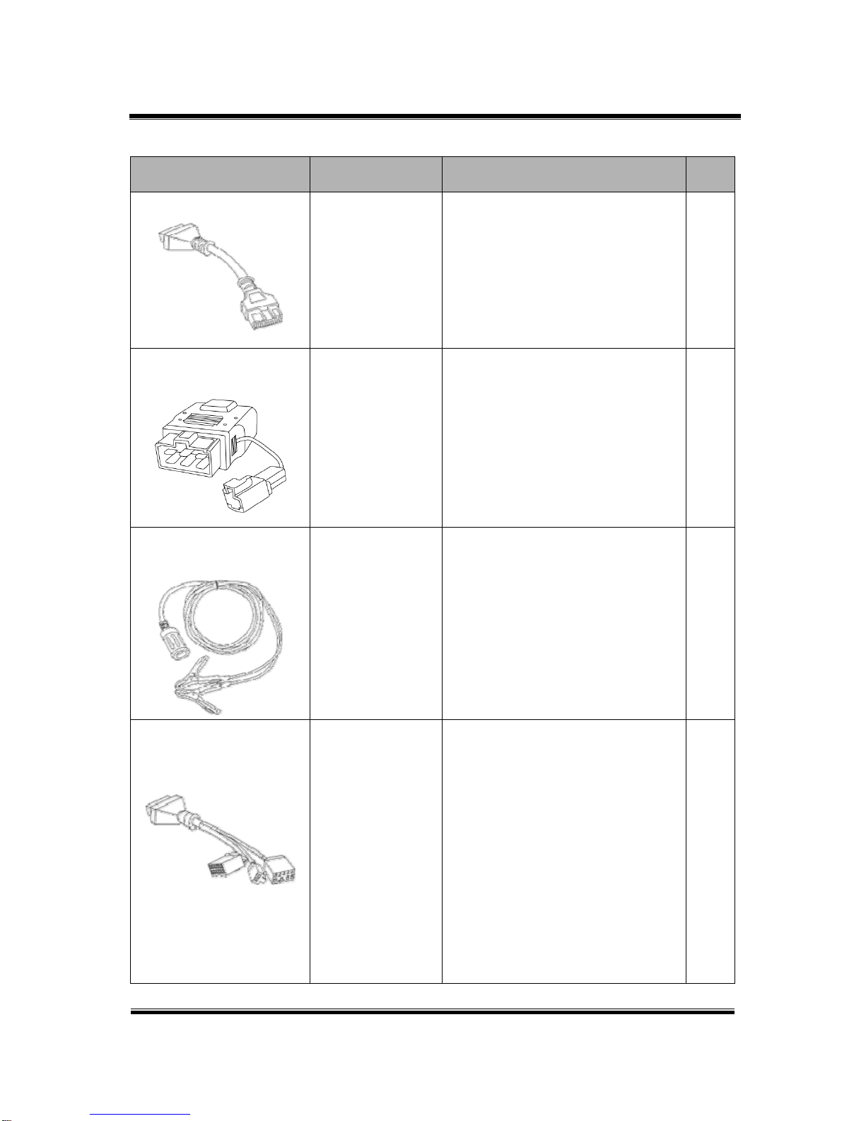
Cable-DLC [26pin -16pin]
GHDM – 241000
DLC main cable for communication
between VCI module and (16pin)
OBD-II diagnosis connector on vehicle.
Length 2.0m. 1
Adapter [16pin-20pin(R)]
GHDM - 244000
DLC Adapter cable [16pin to 20pin(R)]
for DLC Cable (16-26) and 20-pin
diagnosis connector on vehicle.
20pin (R) connector is GRAY in color.
Length: 1.5m.
This cable is used for ECU Upgrade
(Reprogramming) on some Hyundai
vehicles.
1
Adapter [16pin-20pin(A)]
GHDM - 242000
DLC Adapter cable [16pin to 20pin(A)]
for connecting between DLC Cable
(16-26) and 20-pin diagnosis
connector on vehicle. 20pin (A)
connector is BLACK in color.
Length: 1.5m.
1
Adapter [16pin-20pin(B)]
GHDM - 243000
DLC Adapter cable [16pin to 20pin(B)]
for connecting between DLC Cable
(16-26) and 20-pin diagnosis
connector on some vehicles. 20pin (B)
connector is RED in color.
Length: 1.5m.
1
Module: A-01-001 (p.03)
User’s Manual
5
Part name Part number Description Qty.
Cable-DLC [16pin -12pin]
GHDM – 245000
This adapter is connected between
DLC main cable [26pin to 16pin] on the
VCI module and 12pin diagnosis
connecter on some specific vehicles.
Length: 0.2m
1
Adapter [16pin-6pin]
GHDM - 246000
This adapter is connected between
DLC main cable [26pin to 16pin] on the
VCI module and 6pin diagnosis
connecter on some old vehicles.
1
Cable - Battery Power
Extension
GHDM – 24B000
Extension cable for connecting to cigar
jack connecter. Supplies DC power
from the vehicles battery terminals
directly.
Length 3m. 1
Adapter (10-3-3)
GHDM - 248000
DLC adapter cable for reprogramming
and setting Remote Keyless Entry
(RKE). 3 different connectors each
(10, 3 and 3pins) compose the other
side of this 16pin diagnosis connector.
This adapter is used with the main
DLC cable [26pin to 16pin], while
connected to the VCI module.
Length: 0.2m
Used for control modules on some KIA
vehicles.
1
Module: A-01-001 (p.04)

User’s Manual
6
Part name Part number Description Qty.
Adapter (self-test)
GHDM – 24D000
This self-test adapter is used for self-
diagnosis functions that are described
in a separate chapter. Do not use this
adapter except for its specified
purposes. For more information about
self-diagnosis, see chapter A-01-006
Self-test adapter.
1
6p--DC jack
GHDM – 250000
Use this adapter when supplying
power to the VCI main module without
the vehicle’s battery.
1
AC-DC Power adapter
GHDM – 260000
Adapter for supplying power to the VCI
main module from AC power
1
AC power cable
GHDM - 273000
Cable for AC/DC adapter
The socket plug forAC power cable
can be different depends on each
area. Please take this socket plug in
your local site. 1
Module: A-01-001 (p.05)
User’s Manual
7
Part name Part number Description Qty.
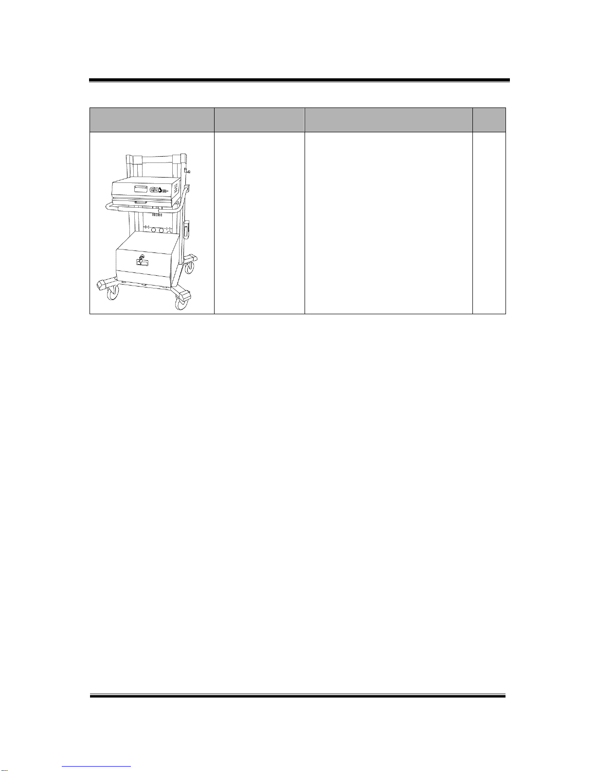
Cart System
GHDM – 5D0000
(Option Item)
Cart system for protecting your GDS
safely.
1
Module: A-01-001 (p.06)
User’s Manual
8
Specifications and Features
Hardware Module: A–01-002 (p.01)
VCI Specifications
General Features
Item Specifications
Micro Controller ARM9 (S3C2410A) @ 208MHz
Memory RAM 32MByte
ROM 32MByte
Operating Voltage 7~35VDC
Temperature Operating
-10℃~ 70℃(14℉~ 158℉): USB Mode
-10℃~ 55℃(14℉~ 131℉): Wireless LAN Mode
Storage -20℃~ 80℃(-4℉~ 176℉)
Relative
Humidity
Operating Noncondensing @ 0℃~ 10℃(32℉~ 50℉)
95%RH @ 10℃~ 30℃(50℉~ 86℉)
70%RH @ 30℃~ 50℃(86℉~ 122℉)
40%RH @ 50℃~ 70℃(122℉~ 158℉)
Storage Noncondensing @ -20℃~ 80℃(-4℉~ 176℉)
Operating Mode Diagnosis Function / Flight Record Function
Current Consumption Typical 350mA @12V
Housing ABS & Rubber Shroud
Dimension 170 × 105 × 33 mm
Weigh 350g
PC Interface
Item Specifications
Wire protocol USB 1.1
Wireless protocol Wireless LAN IEEE 802.11b

User’s Manual
9
FCC ID: TMGGHDM-210000
Contains FCC ID: NI3-IS20V35
This device complies with part 15 of the FCC Rules.
Operation is subject to the following two conditions:
(1) This device may not cause harmful interference.
(2) This device must accept any interference received, including interference that
may cause undesired operation.
VCI (Vehicle Communication Interface)
Item Specifications
CAN CAN 2.0B
K-Line/L-Line ISO-9141, ISO-9141-CARB, KWP-2000
Commercial Veh. SAE-J1708, RS-232C
Data/Control Line Melco Pull-Down UART
Added Interface
Item Specifications
1. VSS Vehicle speed simulation
2. Voltage Output 5 ~20 VDC
FCC/CE Notification
Module: A-01-002 (p.02)
User’s Manual
10
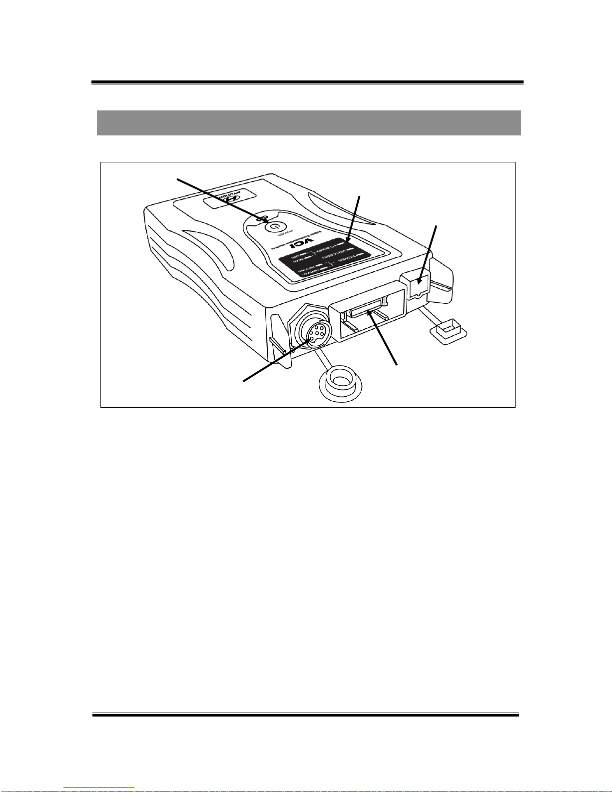
Figure 1. Component Identification
Information Terminal Specifications
Refer To CF-18 Manual or your purchased lap top manual.
Main Components
Trigger Module Connector
Mini USB Connector
DLC Connector
VCI Status Display
Power Switch
Module: A-01-002 (p.03)
Table of contents
Other GDS Medical Equipment manuals


