GDS 10+ OXYMED User manual

PRODUCT DESCRIPTION:
The GDS 10+ Oxymed oxygen enrichment monitor has been specically designed to monitor oxygen levels
in the vicinity of assisted breathing apparatus requiring oxygen cylinders or dedicated oxygen supply lines.
The compact style oers functionality for the monitor to be used as a xed or a transportable device,
boasting further benets for quick installation via a standard wall socket outlet.
GDS 10+ OXYMED
OXYGEN MONITOR

Technical
Gas Type Oxygen
Input Voltage
12~30v DC – 24v nominal
Optional Mains 230/115vAC 50/60hz
Nominal 30mA – 120mA full alarm
Output Standard
Analogue 4~20 mA (250 ohms max) – sink/source
(source mode – standard)
Option 1~5v output – solder G
CV–Sensor Cable 3 core screened
Alarm Relay
Main relay S.P.C.O. 3A/230v AC
Fire Alarm panel signalling – cut F
Trip Indicator LED – trip point selectable 10% to full scale
(Auto reset)
On board sounder
Auxiliary output DC volts – standard–as input volts 24v
DPM – gas readout display – (zero and span potentiometers used
only for DPM setting)
www.gds–technologies.co.uk
SET UP PROCEDURE
Installation
Siting of the equipment should be chosen with regard to the
following points:
1. Safe area use only (not hazardous zone)
2. Away from sources of heat and with room for adequate air
circulation.
3. Within easy reach for operating and maintenance personnel.
4. Connecting cables to be electrically shielded.
5. For further information regarding sensor location see our website
www.gds–technologies.co.uk.
Note: Sensor cables should not be run in the same ducting as power
cables.
Removing Lid (30J)
Using a 2.5mm Allan key withdraw the two lid screws until they clear
the lid bezels. Push the lid up until it is stopped by the circuit board
located inside the enclosure; pull one side to remove the lid.
Mounting
Direct wall mount – use M4 or No.8 screws through the membrane
of the 4 stand–os. Where the stand–os are to be removed (rotate
each stand–o using pliers) drill at mounting points marked C or
utilise knock out slots.
For surface mount box drill at points B (2 o)
For conduit box xing drill at points A (2 o)
Supply Input
Ensure that the supply is correct for the voltage rating of the
indicator. Ensure that the supply is OFF before making any
connections and wire only in accordance with the terminal detail.
Calibration (factory set)
1. Connect a digital voltmeter (miIIivolt range) to the X and Y test
terminals, the CV is preset in the current source mode.
2. Remove the sensor terminal connector from the PCB J4 or yellow
wire and adjust the 4mA potentiometer for 4mA (4mV).
3. Where a digital panel meter is tted to the CV card the reading
may be adjusted by the DPM Zero potentiometer.
Reconnect the cell and allow reading to stabilise adjust the DVM
reading to 17.3mV (20.8% ambient oxygen) using the 20mA
potentiometer.
Where a Digital panel meter is tted the display may be adjusted by
using the DPM S potentiometer (span).
Alarm Trip Point Adjustment (factory set)
This level will normally be set at 23% for oxygen.
1. Connect the DVM as above, using the 20mA potentiometer adjust
for the required trip level (OM DPM).
2. Adjust the alarm level potentiometer until the alarm LED just
comes on.
3. Using the 20mA potentiometer re–adjust the DVM to 17.3mV.
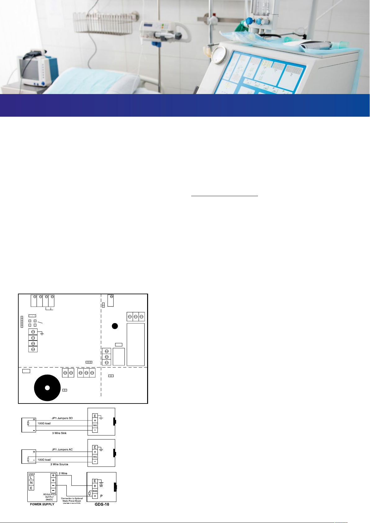
The above adjustment may be carried out in house by connecting
the CV transmitter directly to a DC power supply and connecting a
100Ω load resistor. See diagrams on left.
Should a full board be required to operate on a 2 wire 4-20mA loop
then the alarm relay / LED must be disabled – remove JP2.
A
B
C
D
XP
-
-
+
-
+
+
YW
PYW
SENSOR
FIELD TERMINALS
TO GDS
ALARM PANEL
PCN149
E
Y
20mA
4mA
TP2
TP4
TP1
RV3
JP1
RV4
TP3
WY P
No CNc
NC
C
NO
-+
Sensor Terminal
Sounder Mute
Sounder
FULL CV BOARD
T
RELAY
BOARD
CV
TRANSMITTER
EOL
Output Signal
Adjust
Test Points
Alarm Level
Adjust
Alarm
LED
JP2
20mA
4mA
Span
Zero
DPM
E
A
JP1
-+
WYR
-+
J4
JP3
JP4
XY
B
C
D
W+
Y SIG
P -Field Terminals
to GDS Alarm Unit
U5
LK1
A L
SAFE AREA BOARD EExd BOARD
-
+
-
+
E
SIG
-
+
-
+
E
SIG
JP1 Jumpers BD
JP1 Jumpers AC
3 Wire Sink
100Ω load
100Ω load
3 Wire Source
2 Wire
24vDC
24v DC
Output
WY P
No CNc
NC
C
NO
-+
+
Sensor
Terminal
Sounder
RELAY
BOARD
Sensor
Terminal
EOL
Output Signal
Adjust
Test Points
Alarm Level
Adjust
Alarm
LED
JP2
20mA
4mA
Span
Zero
DPM
E
A
JP1
-+
WYR
-+
J4
JP3
JP4
XY
B
C
D
W+
Y SIG
P -Field Terminals
to GDS Alarm Unit
U5
LK1
A L
T
1A
Relay
RL2
3A
Relay
RL1
-
24v DC
Output
+
-

1. The Hazards – Fire & Explosion
Further information
https://www.hse.gov.uk/pubns/indg459.htm Oxygen enrichment
is the term often used to describe a situation where the oxygen
level is greater than in the air we breathe (approximately 21%
Oxygen). This may vary slightly depending upon local conditions
i.e. the number of people within a given space or where oxygen is
being displaced by normal day to day events.
When enrichment occurs, even a small increase in the oxygen
level to just 24% can create a dangerous situation where:
• It becomes easier to start a re, which will then burn hotter and
more ercely than in normal air.
• It may be almost impossible to put the re out
The main danger to people from an oxygen enriched atmosphere
if ignited is that hair or clothing can easily catch re causing
serious or even fatal burns while receiving oxygen treatment.
2. Oxygen Enrichment Alarm – Action
Action where oxygen enrichment is suspected or indicated:
• The instrument alarm will sound with the red LED illuminating
• Where possible turn o the oxygen supply
• Remove any potential ignition points
• Make sure the room is well ventilated
• Find the source of any leak and remedy
• It is possible that oxygen may contaminate clothing or bedding
within the area. If you suspect contamination remove items
outside for airing
3. Siting the Equipment
Siting of the equipment should be chosen with regards to the
following points.
• Away from sources of heat with room for adequate air
circulation
• Convenient to a 230v mains socket outlet
• Within easy access and audible distance of local sta
• Within the target area at 1 to 1.5m height
4. Operation
The instrument may be a permanent xture or be used as a
transportable device and will automatically power up and operate
when connected to a 230v mains supply.
When rst powered up the sensor cell will require 2 to 3 minutes
to stabilize and achieve the correct ambient oxygen reading.
The instrument is designed for continuous operation and should
only be switched o when permanently no longer required or is
undergoing routine service.
5. Key Information
• Normal ambient Oxygen level 20.8 to 21%
• Instrument alarm set point 23% oxygen
• Critical Oxygen Enrichment level 24%
• Alarm status – continuous sounder and red LED indicator.
Note: the instrument sounder and LED cannot be reset beyond
the trip point
• Full scale reading for the instrument is 25% Oxygen
6. Technical and Maintenance
For instrument technical details see page 2.
The sensor cell mounted in the base of the instrument will
require replacement at 18–month intervals, contact your
equipment supplier for details.
www.gds–technologies.co.uk
ENVIRONMENTAL DATA

GDS 10+ Oxymed Fixed or Transportable
Channels Single Channel
Measurements Oxygen – 0 ~ 25% vol.
Channel Outputs Analogue output 4–20mA – option 1~5 volts. 250 ohms max load
Relays
S.P.C.O. per relay – auto reset
RL1 – 3A/230v AC control relay
RL2 – 1A/24v DC signal relay
Single Stage Alarm Oxygen Enrichment
Power 230/115v AC
12 to 30v DC – optional
Panel Indication Alarm – Red LED
Audible Alarm Auto reset 75dBs @ 1m
Operating Temperature –10 to + 50° C
Storage Temperature +5° C to + 55° C
Humidity 0–95 non condensing
Ingress Protection IP64 Weatherproof
Dimensions H–147 W–145 D–100mm (AC Version)
Weight 0.76KG (AC Version)
Enclosure Material ABS Flame Retardant FR40 – Lid Screws M4SS
Finish – Signal White RAL 9003
Notes Mains lead supplied as standard. For additional information, please see C1798
SPECIFICATION
GDS Technologies Ltd operates under an integrated quality, health and safety and environmental management system certied to ISO 9001, ISO 45001 and ISO 14001 by NQA Certication Ltd.
This document is not contractual and the equipment specication may be modied at any time without prior notice.
E: sales@gds–technologies.co.uk T: +44 (0)113 286 0166
GDS TECHNOLOGIES LTD | FUSION POINT | ASH LANE | GARFORTH | LEEDS | LS25 2GA | UK www.gds–technologies.co.uk
GDS 10+ OXYMED
OXYGEN MONITOR
Specication Sheet Ref C1821B
Other GDS Medical Equipment manuals