manuals.online logo
Brands
  1. Home
  2. •
  3. Brands
  4. •
  5. GE Interlogix
  6. •
  7. Accessories
  8. •
  9. GE Interlogix ShatterPro Plus 5885 User manual

GE Interlogix ShatterPro Plus 5885 User manual

1
ShatterPro Plus 5885
Glassbreak
coverage
12’
12’
PIRcoverage
Microphone
JumperJ1for
LEDlatch
JumperJ2for
separateglassbreack
andPIR
PET
ALLEY
WIDE
ANGLE
SPOT
PET
ALLEY
V
E
R
T
I
C
A
L
B
A
R
R
I
E
R
Lens
Microphone
JumperJ1for
LEDlatch
JumperJ2forseparate
glassbreakandPIR
Maskingkit
Coverplate
Glassbreakcoverage
12’
PIRcoverage
12’ Glassbreakcoverage
PIRcoverage
Wall Mount Corner Mount
Ceiling Mount
ShatterProPlus
Motion Sensitive Acoustic Sensor
Model 5885
Installation Instructions
Wiring
Strip back the outer jacket on your wiring cable. This will
allow wires to flex in the case. Make sure the cable is slack in
the wall to avoid stressing the wires at their connections. The
unit should be connected to a UL listed power supply
capable of providing 4 hours of standby power.
Mounting
Ceiling Mount
1. Mount unit in direct line of sight of windows to be
protected.
2. Sensor can be mounted as close as 3.3 feet (1 m) from
glass and up to 12 feet (3.7 m) from glass.
3. Select appropriate lens mask for field of view of PIR.
4. Perform glassbreak and PIR walk test.
Note: When ceiling mounted, be sure to insert
“single spot” mask to reduce potential for false
alarms.
Wall or Corner Mount
1. Do not aim sensor directly at window - install so PIR
is covering the area of room you expect to have
occupied.
2. Sensor can be mounted as close as 3.3 feet (1 m) from
glass and up to 12 feet (3.7 m) from glass.
3. Select appropriate lens mask for field of view of PIR.
4. Perform glassbreak and PIR walk test.
-+
PIR
NC PIR
COM GB
NC GB
COM
Terminalsfor Power
9-16VDC Terminals for
PIRRelay Terminalsfor
GlassbreakRelay
2ShatterPro Plus 5885
WIDE
ANGLE
AlignNotch
withDimple
AlignNotch
withRib
Cutto
MatchLens
Insideof
FrontCover
Zone Pattern Masking the PIR
Choose which masking plate you need, if any, and cut to
match the lens. Insert behind the lens on the front cover by
pressing over 3 mounting pins. Once the front cover is
installed the masking plate will be held tight against the
lens.
Note: Masking plates have a notch to prevent
incorrect installation. The notch matches a rib in
the front cover.
Note: To correctly mount the PetAlley mask, the
lens must be removed from the front cover and
rotated 180°and cut to fit.
Wall Mount
NoMask
Note: Intruder must enter
coverage pattern 3-4 feet (1-1.2
m) to cross one zone for
detectionof alarm. False alarm
sources, such as heaters,
should be kept out of the
coverage pattern.
360°Ceiling Mount
With Single Spot Mask
15’(4.8m) x 20’ (6.2 m)
capturezone
25’(7.2m)diameter
coveragepattern
Top View
0
54°38.4°
20°
54°38.4°
20°
0°
7’
2.1m
30’
9.1m 40’
12.2m
10’
3.0m 20’
6.1m 30’
9.1m 40’
12.2m
Side View
0
Wall Mount
With Wide Angle Mask
7’
2.1m
30’
9.1m 40’
12.2m
10’
3.0m 20’
6.1m 30’
9.1m 40’
12.2m
Side View
Top View
0
0
90°
7’
2.1m
40’
12.2m
10’
3.0m 20’
6.1m 30’
9.1m 40’
12.2m
Side View
010°
0
7°
Wall Mount
With Single Spot Mask
Top View
7’
2.1m
40’
12.2m
10’
3.0m 20’
6.1m 30’
9.1m 40’
12.2m
Side View
010°
0
Wall Mount
With Vertical Barrier Mask
Top View
Wall Mount
With Pet Alley Mask
90°
3’
0,9m
30’
9.1m
40’
12.2m
10’
3.0m 20’
6.1m 30’
9.1m 40’
12.2m
Side View
Top View
0
0
PET
ALLEY
ROTATE LENS
180
o
Cutto
MatchLens
Insideof
FrontCover
Rotate
Lens180°
3
ShatterPro Plus 5885
®
Application Tips
The ShatterPro Plus provides two separate relays, one for
the glassbreak sensor and one for the PIR. This configura-
tion allows the ShatterPro Plus to be used in a variety of
applications.
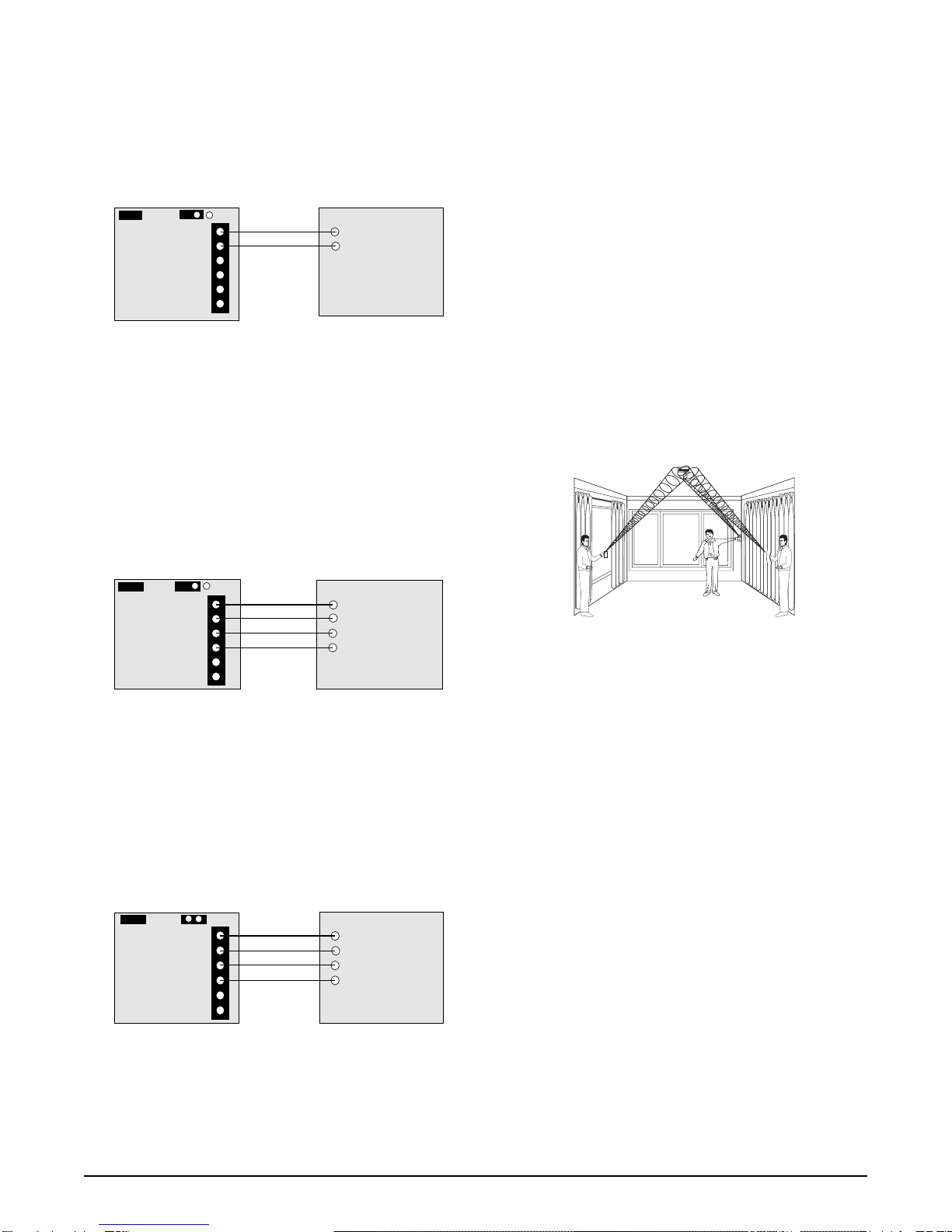
Application 1 - 24 Hour Glassbreak
In this application, the glassbreak relay is wired to a separate
24-hour zone and Jumper 2 is placed across one pin. Now,
any time a person enters the field of view of the PIR, the
glassbreak sensor will be disabled. The glassbreak sensor
willautomaticallyturnbackon oneminuteafterthePIR’s
fieldof viewis vacated.This applicationis idealfor kitchens,
garages, and other small, accoustically-live rooms that may
incur loud occupant-generated sounds. It is also great for
24-hour perimeter protection in commercial installations that
employ access control.
Application 2 - 24-Hour Glassbreak and
Interior Backup PIR
In this application, the glassbreak relay is wired to a 24-hour
zone, the PIR relay is wired to a separate interior zone, and
Jumper 2 is placed across one pin. The PIR relay is wired to
the control panel to provide PIR backup for interior protec-
tion. Now when the interior zone is armed, the PIR will also
act as a motion detector that will trigger an alarm if someone
enters the room. This application is an affordable way to get
two sensors in one installation.
Application 3 - Perimeter Glassbreak and
Interior Backup PIR
In this application, the glassbreak relay is wired to a separate
perimeter (non 24-hour) zone, the PIR relay is wired to a
separate interior zone, and Jumper 2 is placed across two
pins. This configuration is a very affordable way to get two
sensors in one, a glassbreak and a PIR. It’s perfect for
installations that don’t require 24-hour operation, but are
armed at night, during unoccupied hours, or during quiet
occupied hours.
Testing the Sensor
GE Interlogix recommends testing the sensor to confirm that
the field of view is set correctly and that the glassbreak
detector will detect at the desired mounting location.
To test the fieldof view: Walk into the intended occupied
area. The green LED should blink at 1 Hz for 1 minute. This
means that the sensor has adjusted to presence in the room
and turned off the glassbreak alarm relay for 1 minute. It will
turn the glassbreak on only after no movement has been
detected for 1 minute. The LED will also hold 4 seconds
solid green indiating motion detection by the PIR.
To test the glassbreakonly: Place the Jumper J2 on two
pins so the motion sensing device is separated from
glassbreak. Place the 5709C tester next to the microphone
and put the unit into test mode by firing off the tester. The
unit will be blinking red. Position yourself next to the glass
you want to detect, select the appropriate glass type, and
test the unit If drapes or blinds are present, test behind
them. The LED will go solid red for 4 seconds if glass is
within detection range.
LED Indicators for Testing and Alarm
GlassbreakAlarm = 4 seconds solid red
Glassbreak Test = 1Hz blinking red for 1minute
Glassbreak Latched = Solid red
Hand Clap Test = 2 red blinks
PIRAlarm = 4 seconds solid green
PIR Shunting Glassbreak = 1 Hz blinking green for 1 minute
Note: Each time the glassbreak sensor alarms, it
also goes into test mode for 1 minute.
Checking the ShatterPro Plus
The ShatterProPlus can be checked by the installer or end-
user while in normal mode by simply clapping hands loudly
under the sensor. The LED will blink twice, but the sensor
will not trip. This verifies visually that the microphone and
circuit board are functioning.
When the ShatterProPlus trips to an actual alarm condition,
it will latch solid for 4 seconds, then start blinking for 1
minute.At the end of 1 minute, the LED will extinguish
unlessset for “LATCHING LED”.
Using Latching LED
1. Remove Jumper J1 to latch the LED for glassbreak.
2. When the unit alarms for glassbreak, the LED will
remain solid red after exiting test mode.
3. Reset the unit by removing power for at least 1 second.
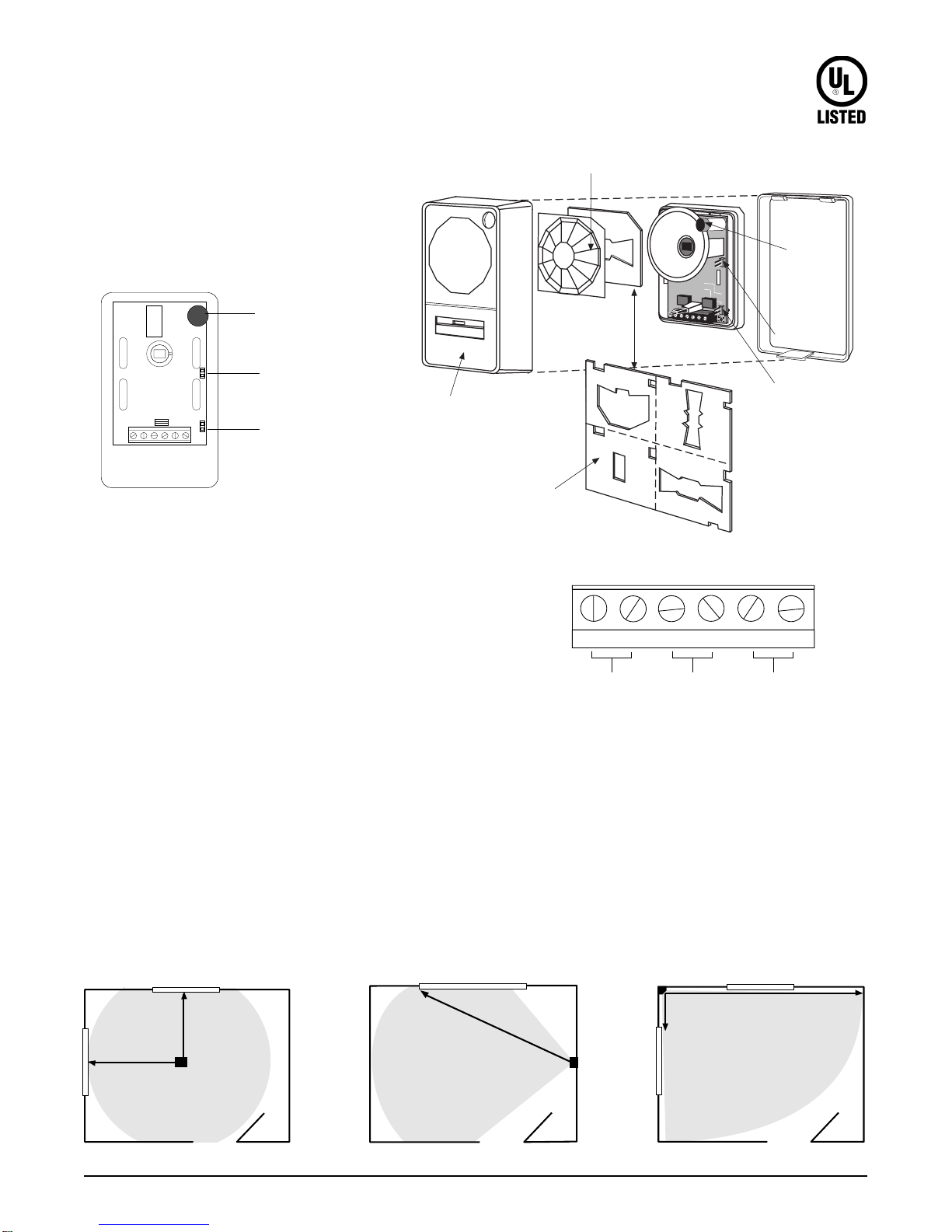
Jumper1 Jumper2
GB COM
GB NC
PIR COM
PIR NC
+
-
5885
Circuit
Board
24-HourZone
Control
Panel
Jumper1 Jumper2
GB COM
GB NC
PIR COM
PIR NC
+
-
5885
Circuit
Board
24-HourZone
Control
Panel
InteriorZone
Jumper1 Jumper2
GB COM
GB NC
PIR COM
PIR NC
+
-
5885
Circuit
Board
Non24-Hour
PerimeterZone
Control
Panel
InteriorZone
Ordering Information
Description Model Number Color Listing
ShatterProPlus 5885-W White UL639
HandHeldTester 5709C
12287 Rev F 09/03
Specifications
Electrical
Operationalvoltage..................................................9to16VDC
Currentdraw.......................................15mAtypical,30mAmax.
Alarm outputs......Normally closed, open 4 seconds on alarm
Onresistance...........................................5to 15 Ohms
Offresistance..............................................>1MOhms
Maximumlooprating
(relayortamperloop)..........................16VDC,50mA
Fails safe and opens on power loss
Wiregauge ...............................................................14- 22AWG
Environmental
Lightning suppression....................400 watts for 1 msec pulse
Operatingtemperature............0°F to 120°F(-18°C to +50° C)
RFIimmunity..............................20V/meterfrom1to1000MHz
Humidity.........................................10% to 90% noncondensing
➝
➝
➝
➝
1.2"
3.1cm
2.2”
(5.6 cm)
3.7”
(9.4 cm)
Dimensions
PIR Features
Pulsecount................................Bi-directional, 1 zone(2 pulses)
with Motion Verification
Range
1.WideAngle(90°)....................................30’x30’(9.1mx9.1m)
7’ (2.1 m) mounting height
2.360°Ceiling..........15’ x 20’(4.6mx6.1m)at8’ (2.4 m)height
16’x 30’(4.9 m x 9.1 m) at 12’(3.7 m)height
Ceiling mounting height up to 12’ (3.7 m)
3.Single Spot.....40’ (12.2 m)range, 7’ (2.1m)mounting height
4.VerticalBarrier..40’(12.2m) range,7’(2.1m)mountingheight
5.PetAlley (90°)..30’(9.1m) range, 3’(0.9 m)mounting height
AcousticGlassbreak Features
Microphone...................................Omnidirectional 360°electret
Sensitivitysetting........................................................Factory set
Range..............................12’(3.7m)fromceilingtowindowwall
12’(3.7 m) to side wall
Glass types detected:
Plateglass.....................1/8”(3.2mm)to 1/4” (6.4 mm)
Tempered glass.............1/8” (3.2 mm)to1/4”(6.4mm)
Wiredglass.............................................. 1/4” (6.4mm)
Laminatedglass.......................................1/4”(6.4mm)
Mounting location.....Ceiling or any wall except opposite wall
Minimumdistancefromglass........................................3.3’(1m)
Minimumglass size......................................1’ (0.3m)x2’(0.6m)
Dimensions.............................................................3.7”(9.4 cm) H
2.2” (5.6 cm) W
1.2” (3.1 cm) D
Housingmaterial............................Flame retrardantABSplastic
Color.............................................................................White/white
Shunting feature.........Glassbreak automatically turns back on
1 minute after vacating PIR’s field of view
www.GE-Interlogix.com
© 2003GEInterlogix
12345 SW Leveton Drive
Tualatin, OR 97062
Phone:503-692-4052
USA & Canada: 800-547-2556
Technical Service: 800-648-7424
FaxBack:800-483-2495
GE Interlogi
x

This manual suits for next models

2

Popular Accessories manuals by other brands

MTS Systems Level Plus M-Series MR Brief operation manual for safe use

MTS Systems

MTS Systems Level Plus M-Series MR Brief operation manual for safe use

Snom M700 manual

Snom

Snom M700 manual

AutoCarDiag El-50448 instructions

AutoCarDiag

AutoCarDiag El-50448 instructions

netvox R311K user manual

netvox

netvox R311K user manual

Winland Humid-Alert HA-1 manual

Winland

Winland Humid-Alert HA-1 manual

Gin One G manual

Gin

Gin One G manual

WT sensor PC312 manual

WT sensor

WT sensor PC312 manual

Johnson Controls NS Series installation instructions

Johnson Controls

Johnson Controls NS Series installation instructions

Honeywell AWM700 Series installation instructions

Honeywell

Honeywell AWM700 Series installation instructions

esera EOS 100 user guide

esera

esera EOS 100 user guide

Emerson Micro Motion ELITE CMF200A installation manual

Emerson

Emerson Micro Motion ELITE CMF200A installation manual

QNAP QG-103N Review guide

QNAP

QNAP QG-103N Review guide

Labkotec idOil-OIL Installation and operating instructions

Labkotec

Labkotec idOil-OIL Installation and operating instructions

ROSE DISPLAYS ANOFRAME ROUND NO LOAD WITH MULTICLIPS manual

ROSE DISPLAYS

ROSE DISPLAYS ANOFRAME ROUND NO LOAD WITH MULTICLIPS manual

Hiltron security FX55D manual

Hiltron security

Hiltron security FX55D manual

Jaquet Green line E12A operating instructions

Jaquet

Jaquet Green line E12A operating instructions

IKEA tradfri manual

IKEA

IKEA tradfri manual

Vortice Kit Vario CO2 Instruction booklet

Vortice

Vortice Kit Vario CO2 Instruction booklet

manuals.online logo
manuals.online logoBrands
  • About & Mission
  • Contact us
  • Privacy Policy
  • Terms and Conditions

Copyright 2025 Manuals.Online. All Rights Reserved.