GE Multilin 745 Use and care manual

IISO9001:2000
G
E
M
U
L
T
I
L
I
N
R
E
G
I
S
T
E
R
E
D
GE Grid Solutions
650 Markland Street
Markham, Ontario
Canada L6C 0M1
Tel: +1 905 927 7070 Fax: +1 905 927 5098
Internet: http://www.gegridsolutions.com
745 revision: 5.2x
Manual Part Number: 1601-0162-A9
GE publication code: GEK-106636H
745
Transformer Protection System
Communications Guide
GE
Grid Solutions
*1601-0162-A9

© 2017 GE Multilin All rights reserved.
GE Multilin 745 Transformer Protection System Communications Guide for revision 5.2x.
745 Transformer Protection System, EnerVista, EnerVista Launchpad, EnerVista 745 Setup, and FlexLogic are registered
trademarks of GE Multilin
The contents of this manual are the property of GE Multilin This documentation is furnished on license and may not be
reproduced in whole or in part without the permission of GE Multilin The content of this manual is for informational use
only and is subject to change without notice.
Part numbers contained in this manual are subject to change without notice, and should therefore be verified by GE
Multilin before ordering.
Part number: 1601-0162-A9 (March 2017)

TABLE OF CONTENTS
745 TRANSFORMER PROTECTION SYSTEM – COMMUNICATIONS GUIDE toc–i
Table of Contents
1: OVERVIEW DESCRIPTION ..................................................................................................................................... 1
PROTOCOLS .......................................................................................................................... 1
PHYSICAL LAYER .................................................................................................................. 1
2: MODBUS PROTOCOL OVERVIEW ........................................................................................................................................... 1
GE MULTILIN MODBUS IMPLEMENTATION ....................................................................... 1
ELECTRICAL INTERFACE ....................................................................................................... 1
DATA FRAME FORMAT AND DATA RATE ............................................................................. 2
DATA PACKET FORMAT ........................................................................................................ 2
CRC-16 ALGORITHM .......................................................................................................... 3
MESSAGE TIMING ................................................................................................................. 4
MODBUS FUNCTIONS .................................................................................................................... 4
SUPPORTED MODBUS FUNCTIONS .................................................................................... 4
READ ACTUAL VALUES OR SETPOINTS ............................................................................... 4
EXECUTE OPERATION ........................................................................................................... 5
STORE SINGLE SETPOINT ..................................................................................................... 6
STORE MULTIPLE SETPOINTS .............................................................................................. 7
EXCEPTION RESPONSES ....................................................................................................... 7
READING THE EVENT RECORDER ........................................................................................ 8
READING TRACE MEMORY ................................................................................................... 8
ACCESSING DATA VIA THE USER MAP ................................................................................ 9
FUNCTION CODE SUBSTITUTIONS ...................................................................................... 11
MODBUS MEMORY MAP ............................................................................................................... 12
MEMORY MAP ORGANIZATION ........................................................................................... 12
745 MEMORY MAP .............................................................................................................. 13
MEMORY MAP DATA FORMATS ........................................................................................... 69
3: DNP PROTOCOL OVERVIEW ........................................................................................................................................... 1
DEVICE PROFILE DOCUMENT .............................................................................................. 1
IMPLEMENTATION TABLE ..................................................................................................... 2
DNP POINT LISTS .............................................................................................................................. 4
BINARY INPUT / BINARY INPUT CHANGE .......................................................................... 4
BINARY OUTPUT / CONTROL RELAY OUTPUT BLOCK ....................................................... 4
ANALOG INPUT / ANALOG INPUT CHANGE ....................................................................... 6

TOC–II 745 TRANSFORMER PROTECTION SYSTEM – COMMUNICATIONS GUIDE
TABLE OF CONTENTS

745 TRANSFORMER PROTECTION SYSTEM – COMMUNICATIONS GUIDE 1–1
745 Transformer Protection
System Communications Guide
Chapter 1: Overview
GE
Grid Solutions
Over view
Description
Protocols The GE Multilin 745 Transformer Protection System communicates with other
computerized equipment such as programmable logic controllers, personal computers, or
plant master computers using either the AEG Modicon Modbus protocol or the Harris
Distributed Network Protocol (DNP), Version 3.0. Following are some general notes:
• The 745 relay always act as slave devices meaning that they never initiate
communications; they only listen and respond to requests issued by a master
computer.
• For Modbus, a subset of the Remote Terminal Unit (RTU) format of the protocol is
supported which allows extensive monitoring, programming and control functions
using read and write register commands.
• For DNP, the functionality is restricted to monitoring of essential relay data and control
of important relay functions. A complete description of the services available via DNP
may be found in the Device Profile Document which is included in this chapter.
DNP is a complex protocol. As a consequence, it is not possible within the scope of this
manual to provide a description of the protocol's operation in anything approaching the
detail required to understand how to use it to communicate with the relay. It is strongly
recommended that interested users contact the DNP Users Group at http://www.dnp.org
to obtain further information:
Members of the DNP Users Group are eligible to receive complete descriptions of all
aspects of the protocol. The Users Group also operates a website (http://www.dnp.org)
where technical information and support is available.
Physical layer Both the Modbus and DNP protocols are hardware-independent so that the physical layer
can be any of a variety of standard hardware configurations including RS232, RS422,
RS485, fiber optics, etc. The 745 includes a front panel RS232 port and two rear terminal
RS485 ports, one of which can also be configured as RS422. Data flow is half duplex in all
configurations. See the 745 instruction manual for details.

1–2 745 TRANSFORMER PROTECTION SYSTEM – COMMUNICATIONS GUIDE
OVERVIEW CHAPTER 1: OVERVIEW
Each data byte is transmitted in an asynchronous format consisting of 1 start bit, 8 data
bits, 1 stop bit, and possibly 1 parity bit. This produces a 10 or 11 bit data frame. This is
important for transmission through modems at high bit rates (11 bit data frames are not
supported by many modems at baud rates greater than 300).
The baud rate and parity are independently programmable for each communications
port. Baud rates of 300, 1200, 2400, 4800, 9600, and 19200 are available. Even, odd, and
no parity are available. See the 745 instruction manual for further details.
The master device in any system must know the address of the slave device with which it
is to communicate. The 745 will not act on a request from a master if the address in the
request does not match the relay's slave address (unless the address is the broadcast
address -- see below).
A single setpoint selects the slave address used for all ports with the exception that for the
front panel port the relay will accept any address when the Modbus protocol is used. The
slave address is otherwise the same regardless of the protocol in use, but note that the
broadcast address is 0 for Modbus and 65535 for DNP. The relay recognizes and processes
a master request (under conditions that are protocol-specific) if the broadcast address is
used but never returns a response.
DNP may be used on, at most, one of the communications ports. Any port(s) not selected
to use DNP will communicate using Modbus. The DNP PORT setpoint is used to select which
port will communicate using DNP.
The maximum time for a 745 relay to return a response to any (non-broadcast) master
request never exceeds 1 second.

745 TRANSFORMER PROTECTION SYSTEM – COMMUNICATIONS GUIDE 2–1
745 Transformer Protection
System Communications Guide
Chapter 2: Modbus Protocol
GE
Grid Solutions
Modbus Protocol
Overview
GE Multilin modbus
implementation
The GE Multilin 745 Transformer Protection System implements a subset of the AEG
Modicon Modbus serial communication standard. Many devices support this protocol
directly with a suitable interface card, allowing direct connection of relays. The Modbus
protocol is hardware-independent; that is, the physical layer can be any of a variety of
standard hardware configurations. This includes RS232, RS422, RS485, fibre optics, etc. The
745 includes a front panel RS232 port and two rear terminal RS485 ports, one of which can
be configured as a four-wire RS422 port. Modbus is a single-master / multiple-slave
protocol suitable for a multi-drop configuration as provided by RS485/RS422 hardware. In
this configuration up to 32 slaves can be daisy-chained together on a single
communication channel.
The GE Multilin 745 is always a Modbus slave. It cannot be programmed as a Modbus
master. The Modbus protocol exists in two versions: Remote Terminal Unit (RTU, binary) and
ASCII. Only the RTU version is supported by the 745. Monitoring, programming and control
functions are possible using read and write register commands.
Additional information on the Modbus protocol can be found on the Modbus website at
http://www.modbus.org.
Electrical interface The hardware or electrical interface is any of the following:
• two-wire RS485 for the rear terminal COM1 and COM2 terminals
• four-wire RS422 for the rear terminal COM1 terminals
• RS232 for the front panel connector
In a two-wire RS485 link, data flow is bidirectional. The four-wire RS422 port uses the
RS485 terminal for receive lines, and two other terminals for transmit lines. In the front
panel RS232 link there are separate lines for transmission and reception as well as a signal
ground wire. In all configurations data flow is half duplex. That is, data is never transmitted
and received at the same time.
RS485 and RS422 lines should be connected in a daisy chain configuration (avoid star
connections) with terminating resistors and capacitors installed at each end of the link, i.e.
at the master end and at the slave farthest from the master. The value of the terminating
resistors should be equal to the characteristic impedance of the line. This is approximately

2–2 745 TRANSFORMER PROTECTION SYSTEM – COMMUNICATIONS GUIDE
MODBUS PROTOCOL CHAPTER 2: MODBUS PROTOCOL
120 Ωfor standard 24 AWG twisted pair wire. The value of the capacitors should be 1 nF.
Shielded wire should always be used to minimize noise. Polarity is important in RS485
communications. The '+' terminal of every device must be connected together for the
system to operate.
Data frame format
and data rate
One data frame of an asynchronous transmission to or from a GE Multilin 745 consists of 1
start bit, 8 data bits, and 1 stop bit. This produces a 10 bit data frame. The 745 can be
configured to include an additional even or odd parity bit if required, producing an 11 bit
data frame.
All ports of the GE Multilin 745 Transformer Protection System support operation at 300,
1200, 2400, 9600, and 19200 baud.
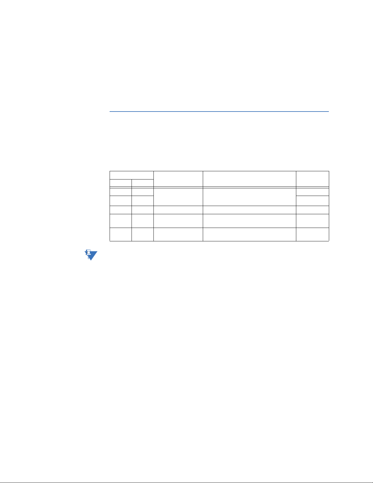
Data packet format A complete request/response sequence consists of the following bytes transmitted as
separate data frames:
A message is terminated when no data is received for a period of 3½ character
transmission times. Consequently, the transmitting device must not allow gaps between
bytes larger than this interval (about 3 ms at 9600 baud).
•Slave address: This is the first byte of every message. This byte represents the user-
assigned address of the slave device that is to receive the message sent by the
master. Each slave device must be assigned a unique address, and only the addressed
slave will respond to a message that starts with its address. In a master query
message the slave address represents the address of the slave to which the request is
being sent. In a slave response message the slave address is a confirmation
representing the address of the slave that is sending the response. A master query
message with a slave address of 0 indicates a broadcast command. All slaves on the
communication link will take action based on the message, but none will respond to
the master. Broadcast mode is only recognized when associated with function codes
05h, 06h, and 10h. For any other function code, a message with broadcast mode slave
address 0 will be ignored.
•Function code: This is the second byte of every message. Modbus defines function
codes of 1 to 127. The 745 implements some of these functions. In a master query
message, the function code tells the slave what action to perform. In a slave response
message, if the function code sent from the slave is the same as the function code
sent from the master then the slave performed the function as requested. If the high
order bit of the function code sent from the slave is a 1 (i.e. if the function code is >
7Fh) then the slave did not perform the function as requested and is sending an error
or exception response.
•Data: This will be a variable number of bytes depending on the Function Code. This
may include actual values, setpoints, or addresses sent by the master to the slave or
by the slave to the master.
Master query message:
Slave address (1 byte)
Function code (1 byte)
Data (variable number of bytes depending on the function code)
CRC (2 bytes)
Slave response message:
Slave address (1 byte)
Function code (1 byte)
Data (variable number of bytes depending on the function code)
CRC (2 bytes)

CHAPTER 2: MODBUS PROTOCOL MODBUS PROTOCOL
745 TRANSFORMER PROTECTION SYSTEM – COMMUNICATIONS GUIDE 2–3
•CRC: This is a two byte error checking code. The RTU version of Modbus includes a
two-byte CRC-16 (16-bit cyclic redundancy check) with every message. The CRC-16
algorithm essentially treats the entire data stream (data bits only; start, stop and
parity ignored) as one continuous binary number. This number is first shifted left 16
bits and then divided by a characteristic polynomial (11000000000000101B). The 16
bit remainder of the division is appended to the end of the message, MSByte first. The
resulting message including CRC, when divided by the same polynomial at the
receiver will give a zero remainder if no transmission errors have occurred. If a GE
Multilin Modbus slave device receives a message in which an error is indicated by the
CRC-16 calculation, the slave device will not respond to the message. A CRC-16 error
indicates that one or more bytes of the message were received incorrectly and thus
the entire message should be ignored in order to avoid the slave device performing
any incorrect operation. The CRC-16 calculation is an industry standard method used
for error detection.
CRC-16 algorithm Once the following algorithm is completed, the working register “A” will contain the CRC
value to be transmitted. Note that this algorithm requires the characteristic polynomial to
be reverse bit ordered. The most significant bit of the characteristic polynomial is dropped,
since it does not affect the value of the remainder. The following symbols are used in the
algorithm:
•—>: data transfer
•A: 16 bit working register
•AL: low order byte of A
•AH: high order byte of A
•CRC: 16-bit CRC-16 value
•i,j: loop counters
•(+): logical exclusive or operator
•Di: i-th data byte (i = 0 to N-1)
•G: 16 bit characteristic polynomial = 1010000000000001 with the most significant bit
dropped and bit order reversed
•shr(x): shift right (the least significant bit of the low order byte of x shifts into a carry
flag, a '0' is shifted into the most significant bit of the high order byte of x, all other bits
shift right one location
The algorithm is:
1. FFFF hex —> A
2. 0 —> i
3. 0 —> j
4. Di (+) AL —> AL
5. j + 1 —> j
6. shr(A)
7. is there a carry? If No, go to 8; If Yes, G (+) A —> A
8. is j = 8? If No, go to 5; If Yes, go to 9.
9. i + 1 —> i
10. is i = N? If No, go to 3; If Yes, go to 11.
11. A —> CRC

2–4 745 TRANSFORMER PROTECTION SYSTEM – COMMUNICATIONS GUIDE
MODBUS PROTOCOL CHAPTER 2: MODBUS PROTOCOL
Message timing Communication message synchronization is maintained by timing constraints. The
receiving device must measure the time between the reception of characters. If three and
one half character times elapse without a new character or completion of the message,
then the communication link must be reset (i.e. all slaves start listening for a new query
message from the master). Thus at 1200 baud a delay of greater than 3.5 x 1/1200 x 10 =
29.2 ms will cause the communication link to be reset. At 9600 baud a delay of greater
than 3.5 x 1/9600 x 10 = 3.6 ms will cause the communication link to be reset. Most master
query messages will be responded to in less than 50 ms.
Modbus functions
Supported Modbus
functions
The second byte of every message is the function code. Modbus defines function codes of
01h to 7Fh. The GE Multilin SR-series Modbus protocol supports some of these functions, as
summarized below.
Since some programmable logic controllers only support function codes 03h (or 04h) and
10h, most of the above Modbus commands can be performed by reading from or writing
to special addresses in the 745 memory map using these function codes. See Function
code substitutions on page 2–11 for details.
Read actual values or
setpoints
Modbus implementation: Read holding registers
GE Multilin implementation: Read actual values or setpoints
Since some PLC Modbus implementations only support one of function codes 03h and 04h,
the 745 interpretation allows either code to be used for reading one or more consecutive
setpoints or actual values. The data starting address determines the data type being read.
Function codes 03h and 04h are therefore identical.
The GE Multilin implementation of Modbus views “holding registers” as any setpoint or
actual value register in the 745 memory map. Registers are 16 bit (two byte) values
transmitted high order byte first. Thus all GE Multilin setpoints and actual values in the
memory map are sent as two byte registers. This function code allows the master to read
one or more consecutive setpoints or actual values from the addressed slave device.
The maximum number of values that can be read in a single message is 120.
Table 2–1: GE Multilin Modbus function codes
Function Code Definition Description Substitute
Hex Dec.
03 3 Read actual values
or setpoints
Read actual value or setpoint registers
from one or more consecutive memory
map registers
04h
04 4 03h
05 5 Execute operation Perform 745 specific operations 10h
06 6 Store single setpoint Write a specific value into a single
setpoint register 10h
10 16 Store multiple
setpoints
Write specific values into one or more
consecutive setpoint registers
---
NOTE

CHAPTER 2: MODBUS PROTOCOL MODBUS PROTOCOL
745 TRANSFORMER PROTECTION SYSTEM – COMMUNICATIONS GUIDE 2–5
Message format and example:
Request to read 3 register values starting from address 0200 from slave device 11.
Execute operation Modbus implementation: Force single coil
GE Multilin implementation: Execute operation
This function allows the master to perform various operations in the 745. The two-byte
value of FF00h must be sent after the operation code for the operation to be performed.
Message format and example:
Request to perform reset operation in slave device 11.
Master query message Example Description
Slave address 11 query message for slave 11
Function code 03 read register values
Data starting address 02 00 data starting at address 0200
Number of registers (high, low) 00 03 3 register values = 6 bytes total
CRC (low, high) 06 E3 computed cyclic redundancy check
Slave response Example Description
Slave address 11 response message from slave 11
Function code 03 read register values
Byte count 06 3 register values = 6 bytes total
Data #1 (high, low) 02 2B register value in address 0200 = 022B
Data #2 (high, low) 00 00 register value in address 0201 = 0000
Data #3 (high, low) 00 64 register value in address 0202 = 0064
CRC (low, high) C8 BA computed CRC code
Master query message Example Description
Slave address 11 query message for slave 11
Function code 05 execute operation
Operation code (high, low) 00 01 remote reset
Code value (high, low) FF 00 perform operation
CRC (low, high) DF 6A computed cyclic redundancy check
Slave response Example Description
Slave address 11 response message from slave 11
Function code 05 execute operation
Operation code (high, low) 00 01 remote reset
Code value (high, low) FF 00 perform operation
CRC (low, high) DF 6A computed cyclic redundancy check

2–6 745 TRANSFORMER PROTECTION SYSTEM – COMMUNICATIONS GUIDE
MODBUS PROTOCOL CHAPTER 2: MODBUS PROTOCOL
Store single setpoint Modbus implementation: Preset single register
GE Multilin implementation: Store single setpoint
This function code allows the master to modify the contents of a single setpoint register in
the addressed slave device. The response of the slave device to this function code is an
echo of the entire master query message.
Message format and example:
Request slave device 11 to write the value 00C8 at setpoint address 1100.
Operation
code
Definition Description
0000 No operation Does not do anything.
0001 Remote reset Performs the same function as the front panel RESET
key.
0002 Trigger trace memory Initiates a waveform capture of trace memory and
increments the “Total Number of Trace Triggers”
registers.
0003 Clear maximum demand
data Performs the same function as the CLEAR MAX
DEMAND DATA actual values command.
0004 Clear event recorder data Performs the same function as the CLEAR EVENT
RECORD DATA actual values command.
0005 Clear loss-of-life data Performs the same function as the CLEAR LOSS-OF-
LIFE DATA setpoints command.
0006 Clear trace memory Clears all trace memory buffers and sets the “Total
number of trace triggers” register to zero.
0007 Clear energy data Performs the same function as the CLEAR ENERGY
actual values command.
Master query message Example Description
Slave address 11 query message for slave 11
Function code 06 store single setpoint value
Data starting address (high, low) 11 00 data starting at address 1100
Data (high, low) 00 C8 data for address 1100 = 00C8
CRC (low, high) 8F F0 CRC computed by master
Slave response Example Description
Slave address 11 response message from slave 11
Function code 06 store single setpoint value
Data starting address (high, low) 11 00 data starting at address 1100
Data (high, low) 00 C8 data for address 1100 = 00C8
CRC (low, high) 8F F0 CRC computed by slave

CHAPTER 2: MODBUS PROTOCOL MODBUS PROTOCOL
745 TRANSFORMER PROTECTION SYSTEM – COMMUNICATIONS GUIDE 2–7
Store multiple
setpoints
Modbus implementation: Preset multiple registers
GE Multilin implementation: Store multiple setpoints
This function code allows the master to modify the contents of a one or more consecutive
setpoint registers in the addressed slave device. Setpoint registers are 16 bit (two byte)
values transmitted high order byte first. The maximum number of register values
(setpoints) that can be stored in a single message is 60.
For example, request slave device 11 to write the value 00C8 at setpoint address 1100, and
the value 0001 at setpoint address 1101.
Exception responses Programming or operation errors happen because of illegal data in a message, hardware
or software problems in the slave device, etc. These errors result in an exception response
from the slave. The slave detecting one of these errors sends a response message to the
master consisting of slave address, function code, error code, and CRC. To indicate that the
response is a notification of an error, the high order bit of the function code is set to 1.
* Some implementations of Modbus may not support these exception responses.
Master query message Example Description
Slave address 11 query message for slave 11
Function code 10 store multiple setpoint values
Data starting address (high, low) 11 00 data starting at address 1100
Number of setpoints (high, low) 00 02 2 setpoint values = 4 bytes total
Byte Count 04 4 bytes of data
Data #1 (high, low) 00 C8 data for address 1100 = 00C8
Data #2 (high, low) 00 01 data for address 1101 = 0001
CRC (low, high) 27 01 CRC computed by master
Slave response Example Description
Slave address 11 response message from slave 11
Function code 10 store multiple setpoint values
Data starting address (high, low) 11 00 data starting at address 1100
Number of setpoints (high, low) 00 02 2 setpoint values = 4 bytes total
CRC (low, high) 46 64 CRC computed by slave
Table 2–2: Modbus error codes
Error Modbus definition GE Multilin implementation
01 Illegal function The function code of the master query message is not a
function code supported by the slave.
02 Illegal data address The address referenced in the data field of the master query
message is not an address supported by the slave.
03 Illegal data value The value referenced in the data field of the master query
message is not allowable in the addressed slave location.
04 Failure in associated
device An external device connected to the addressed slave device
has failed and the data cannot be sent. This response will be
returned if a GE Multilin device connected to the RS485 external
device port of the 745 has failed to respond to the 745.
05* Acknowledge The addressed slave device has accepted and is processing a
long duration command. Poll for status.
06* Busy, rejected
message
The message was received without error, but the slave device is
engaged in processing a long duration command. Retransmit
later, when the slave device may be free.
07* NAK - Negative
Acknowledge The message was received without error, but the request could
not be performed, because this version of the 745 does not
have the requested operation available.
NOTE

2–8 745 TRANSFORMER PROTECTION SYSTEM – COMMUNICATIONS GUIDE
MODBUS PROTOCOL CHAPTER 2: MODBUS PROTOCOL
For example, request to slave device 11 to perform unsupported function code 39h.
Reading the event
recorder
All event recorder data can be read from Modbus registers found in the address range
0800h to 0FFFh. The “Total number of events since last clear” register at address 0804h is
incremented by one every time a new event occurs. The register is cleared to zero when
the event recorder is cleared. When a new event occurs, the event is assigned an 'event
number' which is equal to the incremented value of this register. The newest event will
have an event number equal to the total number of events. This register can be used to
determine if any new events have occurred by periodically reading the register to see if
the value has changed. If the total number of events has increased, then new events have
occurred.
Only the data for a single event can be read from the Modbus memory map in a single
data packet. The “Event record selector index” register at address 0805h selects the event
number whose data can be read from the memory map. For example, to read the data for
event number 123, the value 123 must first be written to this register. All the data for event
number 123 can now be read from the event recorder data registers at addresses 0830h to
086Ah. Only the last 256 events are actually stored in the relay's memory. Attempting to
retrieve data for older events that are not stored will result in a Modbus exception response
when writing to the “Event record selector index”.
The following example illustrates how information can be retrieved from the event
recorder. A SCADA system polls the total number of events register once every minute. It
now reads a value of 27 from the register when previously the value was 24, which means
that three new events have occurred during the last minute. The SCADA system writes a
value of 25 to the event record selector index register. It then reads the data for event
number 25 from the event recorder data registers and stores the data to permanent
memory for retrieval by an operator. The SCADA system now writes the value 26 to the
selector and then reads the data for event number 26. Finally, the SCADA system writes
the value 27 to the selector and then reads the data for this event. All the data for the new
events has now been retrieved by the SCADA system, so it resumes polling the total
number of events register.
Reading trace
memory
All trace memory data can be read from Modbus registers found in the address range
4000h to 4816h. The “Total number of trace triggers since last clear” register at address
4004h is incremented by one every time a new trace memory waveform capture is
triggered. The register is cleared to zero when the trace memory is cleared. When a new
trigger occurs, the captured trace memory buffer is assigned a trigger number which is
equal to the incremented value of this register. The newest captured buffer will have a
trigger number equal to the total number of trace triggers. This register can be used to
determine if any new triggers have occurred by periodically reading the register to see if
the value has changed. If the total number of trace triggers has increased, then new trace
memory waveform captures have occurred.
Master query message Example Description
Slave address 11 query message for slave 11
Function code 39 unsupported function code – error
CRC (low, high) CD F2 CRC computed by master
Slave response Example Description
Slave address 11 response message from slave 11
Function code B9 return unsupported function code with
high-order bit set
Error code 01 illegal function
CRC (low, high) 93 CRC computed by slave

CHAPTER 2: MODBUS PROTOCOL MODBUS PROTOCOL
745 TRANSFORMER PROTECTION SYSTEM – COMMUNICATIONS GUIDE 2–9
Only the data for a single channel of a single trace memory buffer can be read from the
Modbus memory map at a time. The “Trace buffer selector index” register at address
4005h selects the trace memory buffer, and the “Trace channel selector index” register at
4006h selects the trace memory channel, whose waveform data can be read from the
memory map. For example, to read the waveform data for the “Winding 1 phase C current”
of trace memory buffer 5, the value 5 must be written to the trace buffer selector index,
and the value 2 (as per data format F65) must be written to the trace channel selector
index. All the captured waveform data for buffer 5, channel “Winding 1 phase C current”
can now be read from the trace memory data registers at addresses 4010h to 4416h. Only
the trace memory buffers for the last three trace memory triggers are actually stored in
the relay's memory. Attempting to retrieve data for older triggers that are not stored will
result in a Modbus exception response when writing to the trace buffer selector index.
For example, to retrieve information from the trace memory, a SCADA system polls the
total number of trace triggers register once every minute. It now reads a value of 6 from
the register when previously the value was 5, indicating that one new trigger has occurred
during the last minute. The SCADA system writes a value of 6 to the trace buffer selector
index register. It then writes the value of 0 to the trace channel selector index register,
reads the waveform data for “Winding 1 phase A current” of trace buffer 6 from the trace
memory data registers, and stores the data to memory for retrieval by an operator. The
SCADA system now writes the value 1 to the trace channel selector index and then reads
the waveform data for “Winding 1 phase B current”. The SCADA system continues by
writing all other channel numbers to the trace channel selector index, each time reading
the waveform data, until all channels for buffer 6 have been read. All the waveform data for
the new trace memory trigger has now been retrieved by the SCADA system, so it resumes
polling the total number of trace triggers register.
Accessing data via the
user map
The 745 has a powerful user map feature that allows a computer to access up to 120 non-
consecutive registers (setpoints or actual values) by using one Modbus read message.
It is often necessary for a master to continuously poll various values in each of the
connected slave relays. If these values are scattered throughout the memory map,
reading them would require numerous transmissions and would labor the communication
link. The user map can be programmed to join any memory map address to one in the
block of consecutive user map locations, so that they can be accessed by reading (and
writing to, if joined to setpoints) these consecutive locations. The user map feature consists
of:
1. User map addresses 1 to 120 (located at memory map addresses 0180h to 01F7h).
These are the setpoints which store the (possibly discontinuous) memory map
addresses of the values that are to be accessed.
2. User map values 1 to 120 (located at memory map addresses 0100h to 0177h). These
are the access points of the remapped locations. Reading user map value 1 returns
the value at the address stored in user map address 1, user map value 2 the value at
user map address 2, and so on. Writing to any user map value is only possible if the
address stored in the corresponding user map address is a setpoint value.

2–10 745 TRANSFORMER PROTECTION SYSTEM – COMMUNICATIONS GUIDE
MODBUS PROTOCOL CHAPTER 2: MODBUS PROTOCOL
For an example of how to use the user map feature, say the master computer is required
to continuously read the memory map locations shown below from slave 11. Normally,
this would require at least 4 separate master query messages.
1. First, preload the addresses listed in the first column of the table to in user map
addresses 1 to 6 (addresses 0180h to 0185h).
2. Now that the user map addresses have been setup, the required memory map
locations can be accessed via the user map values 1 to 6 (addresses 0100h to 0105h).
Both actual values and setpoints may be read.
Address Description Type
0200h Relay Status actual value
0210h Winding 3 phase time overcurrent flag actual value
0300h Winding 1 phase a 4th harmonic content actual value
0301h Winding 1 phase b 4th harmonic content actual value
0302h Winding 1 phase c 4th harmonic content actual value
2002h Percent differential pickup setpoint
Master query message Example Description
Slave address 11 query message for slave 11
Function code 10 store multiple setpoint values
Data starting address (high, low) 01 80 data starting at address 0180
Number of setpoints (high, low) 00 06 6 setpoint values = 12 bytes total
Byte count 0C 12 bytes of data
Data #1 (high, low) 02 00 0200 →Relay status
Data #2 (high, low) 02 10 0210 →W3 Phase time overcurrent flag
Data #3 (high, low) 03 00 0300 →W1 ΦA 4th harmonic content
Data #4 (high, low) 03 01 0301 →W1 ΦB 4th harmonic content
Data #5 (high, low) 03 02 0302 →W1 ΦC 4th harmonic content
Data #6 (high, low) 20 02 2002 →Percent differential pickup
CRC (low, high) 2F 8A CRC computed by master
Slave response Example Description
Slave address 11 response message from slave 11
Function code 10 store multiple setpoint values
Data starting address (high, low) 01 80 data starting at address 0180
Number of setpoints (high, low) 00 06 6 setpoint values = 12 bytes total
CRC (low, high) 42 8F CRC computed by slave
Master query message Example Description
Slave address 11 query message for slave 11
Function code 03 read register values
Data starting address (high, low) 01 00 data starting at address 0100
Number of registers (high, low) 00 06 6 setpoint values = 12 bytes total
CRC (low, high) C6 A4 CRC computed by master
Slave response Example Description
Slave address 11 response message from slave 11
Function code 03 read register values
Byte count 0C 6 registers values = 12 bytes of data

CHAPTER 2: MODBUS PROTOCOL MODBUS PROTOCOL
745 TRANSFORMER PROTECTION SYSTEM – COMMUNICATIONS GUIDE 2–11
3. Setpoints may be written via the user map. In the example above, to change the value
of restrained differential pickup to 0.20 x CT through the user map, transmit the
following Modbus message:
Function code
substitutions
Most 745 supported Modbus commands can be performed via function codes 03h (or 04h),
and 10h and special memory map addresses.
Function codes 03h and 04h are interchangeable. Both have identical message formats,
and both perform the same action.
Function code 05h (execute operation) can be performed by writing the command as if it
were data in the memory map. For example, to write operation code 01h (reset targets) to
register 0080h, the message format and example is shown below.
Request slave device 11 to reset targets:
Data #1 (high, low) 82 01 Relay status
Data #2 (high, low) 00 01 W3 Phase TOC flag = not operated
Data #3 (high, low) 00 01 W1 ΦA 4th harmonic content = 1% ƒ0
Data #4 (high, low) 00 01 W1 ΦB 4th harmonic content = 1% ƒ0
Data #5 (high, low) 00 01 W1 ΦC 4th harmonic content = 1% ƒ0
Data #6 (high, low) 00 1E Percent differential pickup = 0.30 ×Id
CRC (low, high) 80 F1 CRC computed by slave
Master query message Example Description
Slave address 11 query message for slave 11
Function code 06 store single setpoint values
Data starting address (high, low) 01 85 data starting at address 0185
Data (high, low) 00 14 0014 = 0.30 ×Id
CRC (low, high) 9B 40 CRC computed by master
Slave response Example Description
Slave address 11 response message from slave 11
Function code 06 store single setpoint values
Data starting address (high, low) 01 85 data starting at address 0185
Data (high, low) 00 14 0014 = 0.30 ×Id
CRC (low, high) 9B 40 CRC computed by slave
Master query message Example Description
Slave address 11 query message for slave 11
Function code 10 store multiple setpoints
(substituted for function code 05h)
Data starting address (high, low) 00 80 data starting at address 0080
Number of setpoints (high, low) 00 01 1 register values = 2 bytes total
Byte count 02 2 bytes of data
Data (high, low) 00 01 0001 = operation code 0001h (reset
targets)
CRC (low, high) B5 90 CRC computed by master
Slave response Example Description
Slave address 11 response message from slave 11
Function code 10 store multiple setpoints
Data starting address (high, low) 00 80 data starting at address 0080

2–12 745 TRANSFORMER PROTECTION SYSTEM – COMMUNICATIONS GUIDE
MODBUS PROTOCOL CHAPTER 2: MODBUS PROTOCOL
Function code 06h (store single setpoint) is simply a shorter version of function code 10h
(store multiple setpoints). Using function code 10h, such that the number of setpoints
stored is 1, has the same effect as function code 06h. The message format and example is
shown below.
Request slave device 11 to write the single setpoint value 00C8 at setpoint address 1100.
Modbus memory map
Memory map
organization
Data in the 745 that is accessible via computer communications is grouped into several
sections of the memory map as shown in the table below. All memory map locations are
two-byte (16-bit) values. The following section lists all memory map locations. Addresses
for all locations are in hexadecimal. Consult the range, step, units, and the data format
(listed after the memory map) to interpret the register values.
Number of setpoints (high, low) 00 01 1 setpoint values = 2 bytes total
CRC (low, high) 02 31 CRC computed by slave
Master query message Example Description
Slave address 11 query message for slave 11
Function code 10 store multiple setpoints
(substituted for function code 06h)
Data starting address (high, low) 11 00 data starting at address 1100
Number of setpoints (high, low) 00 01 1 setpoint values = 2 bytes total
Byte count 02 2 bytes of data
Data (high, low) 00 C8 data for address 1100 = 00C8
CRC (low, high) 6B 07 CRC computed by master
Slave response Example Description
Slave address 11 response message from slave 11
Function code 00 store multiple setpoint values
Data starting address (high, low) 11 00 data starting at address 1100
Number of setpoints (high, low) 00 01 1 setpoint values = 2 bytes total
CRC (low, high) 06 65 CRC computed by slave
Table 2–3: Memory map organization
Memory map section Address range Description
Product ID 0000 to 007F Identification and revision information. Read only.
Commands 0080 to 00FF Substitute command locations. Read and write.
User map 0100 to 01FF User map values and addresses. Read and write.
Actual values 0200 to 07FF Read only.
Event recorder 0800 to 0FFF Read only (except “Event record selector index”
register).
Common setpoints 1000 to 1FFF Read and write.
Setpoint group 1 to 4 2000 to 3FFF Read and write.
Trace memory 4000 to 4186 Read only (except “Trace buffer selector index” and
“Trace channel selector index” registers)
Playback memory 6000 to 680F Read and write.

CHAPTER 2: MODBUS PROTOCOL MODBUS PROTOCOL
745 TRANSFORMER PROTECTION SYSTEM – COMMUNICATIONS GUIDE 2–13
745 memory map The Modbus memory map for the 745 Transformer Protection System is shown below. All
addresses are in hexadecimal format.
Table 2–4: 745 memory map (Sheet 1 of 56)
Addr Description Range Step Units Format Default
Product ID (addresses 0000 to 007F, read only)
0000 GE Multilin product device code --- --- --- F1 33 = 745
0001 Hardware revision --- --- --- F13 4 = D
0002 Software revision --- --- --- F14 200
0003 Version number 000 to 999 001 --- F1 000
0004 Bootware revision 000 to 999 001 --- F14 120
0005 Installed options --- --- --- F15 ---
0006 Serial number (4 registers) --- --- --- F33 “A0000000”
000A Manufacture date (2 registers) --- --- --- F23 ---
000C Reserved
000D Reserved
↓↓ ↓ ↓ ↓ ↓ ↓
001F Reserved
Upgrade options (addresses 0020 to 002F, read/write)
0020 New options --- --- --- F15 ---
0021 Modify passcode --- --- --- F33 ---
0022 Reserved
0023 Reserved
↓↓ ↓ ↓ ↓ ↓ ↓
007F Reserved
Commands (Addresses 0080 to 00FF) - Read / Write
Commands
0080 Command operation code --- --- --- F19 ---
0081 Passcode access (4 registers)
Note: From version 5.23 onward, relay
response to read request is 00000000.
--- --- --- F33 00000000
0085 Change passcode (4 registers)
Note: From version 5.23 onward, relay
response to read request is 00000000.
--- --- --- F33 00000000
0089 Reserved
008A Reserved
↓↓ ↓ ↓ ↓ ↓ ↓
008F Reserved
Virtual inputs
0090 Virtual input 1 programmed state --- --- --- F43 0
0091 Virtual input 2 programmed state --- --- --- F43 0
0092 Virtual input 3 programmed state --- --- --- F43 0
0093 Virtual input 4 programmed state --- --- --- F43 0
0094 Virtual input 5 programmed state --- --- --- F43 0
0095 Virtual input 6 programmed state --- --- --- F43 0
0096 Virtual input 7 programmed state --- --- --- F43 0
0097 Virtual input 8 programmed state --- --- --- F43 0
0098 Virtual input 9 programmed state --- --- --- F43 0
0099 Virtual input 10 programmed state --- --- --- F43 0
009A Virtual input 11 programmed state --- --- --- F43 0
009B Virtual input 12 programmed state --- --- --- F43 0

2–14 745 TRANSFORMER PROTECTION SYSTEM – COMMUNICATIONS GUIDE
MODBUS PROTOCOL CHAPTER 2: MODBUS PROTOCOL
009C Virtual input 13 programmed state --- --- --- F43 0
009D Virtual input 14 programmed state --- --- --- F43 0
009E Virtual input 15 programmed state --- --- --- F43 0
009F Virtual input 16 programmed state --- --- --- F43 0
00A0 Reserved
00A1 Reserved
↓↓ ↓ ↓ ↓ ↓ ↓
00EF Reserved
Time/date
00F0 Time (2 registers) --- --- --- F22 ---
00F2 Date (2 registers) --- --- --- F23 ---
00F4 Reserved
00F5 Reserved
↓↓ ↓ ↓ ↓ ↓ ↓
00FF Reserved
User map (addresses 0100 to 01FF, read/write)
User map values
0100 User map value #1 --- --- --- --- ---
0101 User map value #2 --- --- --- --- ---
0102 User map value #3 --- --- --- --- ---
0103 User map value #4 --- --- --- --- ---
0104 User map value #5 --- --- --- --- ---
0105 User map value #6 --- --- --- --- ---
0106 User map value #7 --- --- --- --- ---
0107 User map value #8 --- --- --- --- ---
0108 User map value #9 --- --- --- --- ---
0109 User map value #10 --- --- --- --- ---
010A User map value #11 --- --- --- --- ---
010B User map value #12 --- --- --- --- ---
010C User map value #13 --- --- --- --- ---
010D User map value #14 --- --- --- --- ---
010E User map value #15 --- --- --- --- ---
010F User map value #16 --- --- --- --- ---
0110 User map value #17 --- --- --- --- ---
0111 User map value #18 --- --- --- --- ---
0112 User map value #19 --- --- --- --- ---
0113 User map value #20 --- --- --- --- ---
0114 User map value #21 --- --- --- --- ---
0115 User map value #22 --- --- --- --- ---
0116 User map value #23 --- --- --- --- ---
0117 User map value #24 --- --- --- --- ---
0118 User map value #25 --- --- --- --- ---
0119 User map value #26 --- --- --- --- ---
011A User map value #27 --- --- --- --- ---
011B User map value #28 --- --- --- --- ---
011C User map value #29 --- --- --- --- ---
011D User map value #30 --- --- --- --- ---
Table 2–4: 745 memory map (Sheet 2 of 56)
Addr Description Range Step Units Format Default
Table of contents
Other GE Multilin Protection Device manuals
Popular Protection Device manuals by other brands

ABB
ABB REG316 4 Series operating instructions

STI
STI STI-13000 Series Install

ABB
ABB REX 521 Technical Reference Manual, Standard Configurations

Intratone
Intratone 16-0101 Mounting guide

ACO Haustechnik
ACO Haustechnik ACO Quatrix-K Series Installation information

REXROTH
REXROTH ECS 10 operating instructions