GE Multilin MM200 User manual

LISTED
52TL
IND.CONT. EQ.
E83849
Title page
GE Multilin's Quality
Management System is
registered to ISO9001:2000
QMI # 005094
Digital Energy
Multilin
GE Multilin
215 Anderson Avenue, Markham, Ontario
Canada L6E 1B3
Tel: (905) 294-6222 Fax: (905) 201-2098
Internet: http://www.GEmultilin.com
QuickStart Guide
MM200 revision: 1.11
Manual P/N: 1601-9030-A4
GE publication code: GEK-113401C
Copyright © 2009 GE Multilin
IISO9001:2000
G
E
M
U
L
T
I
L
I
N
R
E
G
I
S
T
E
R
E
D
*1601-9030-A4*
MM200
Motor Management System
Low voltage motor protection and control

© 2009 GE Multilin Incorporated. All rights reserved.
GE Multilin MM200 Motor Management System QuickStart Guide for revision 1.1x.
MM200 Motor Management System, EnerVista, EnerVista Launchpad, EnerVista MM200
Setup, and FlexLogic are registered trademarks of GE Multilin Inc.
The contents of this manual are the property of GE Multilin Inc. This documentation is
furnished on license and may not be reproduced in whole or in part without the permission
of GE Multilin. The content of this manual is for informational use only and is subject to
change without notice.
Part number: 1601-9030-A4 (January 2009)

TABLE OF CONTENTS
MM200 MOTOR MANAGEMENT SYSTEM – QUICKSTART GUIDE toc–1
Table of Contents
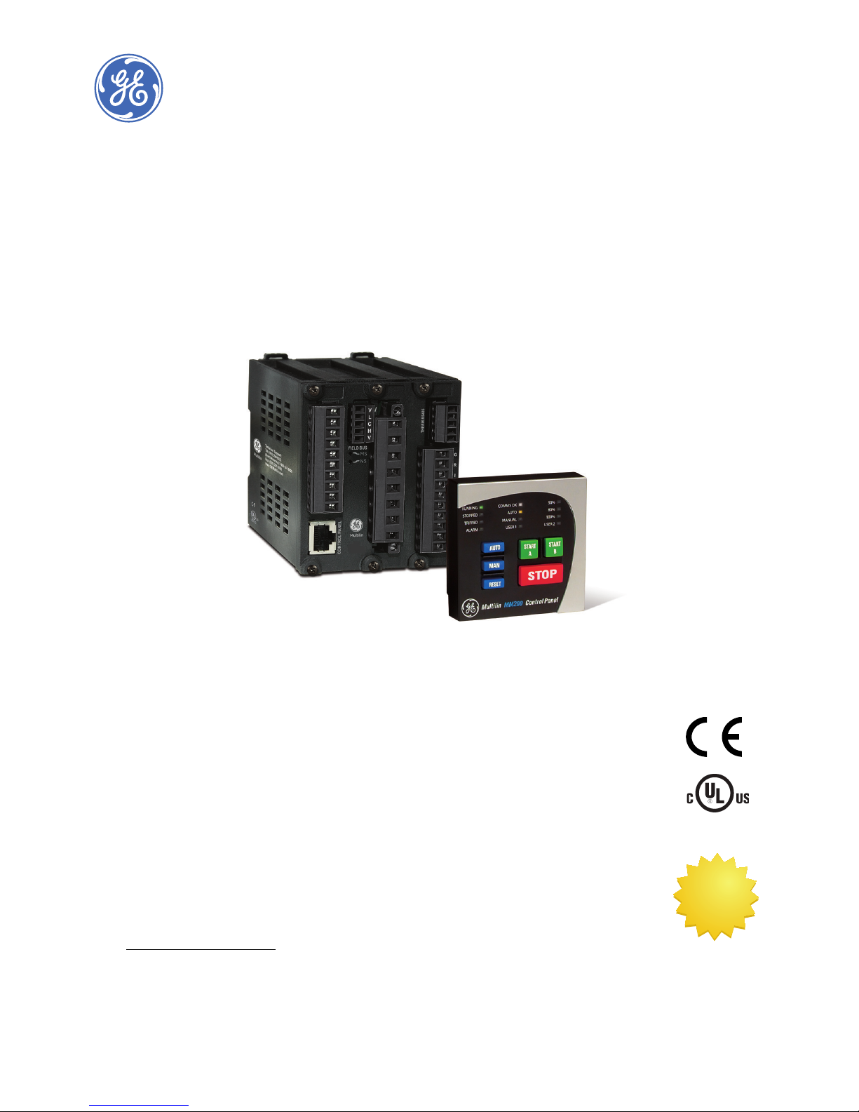
Overview ..........................................................................................................................1
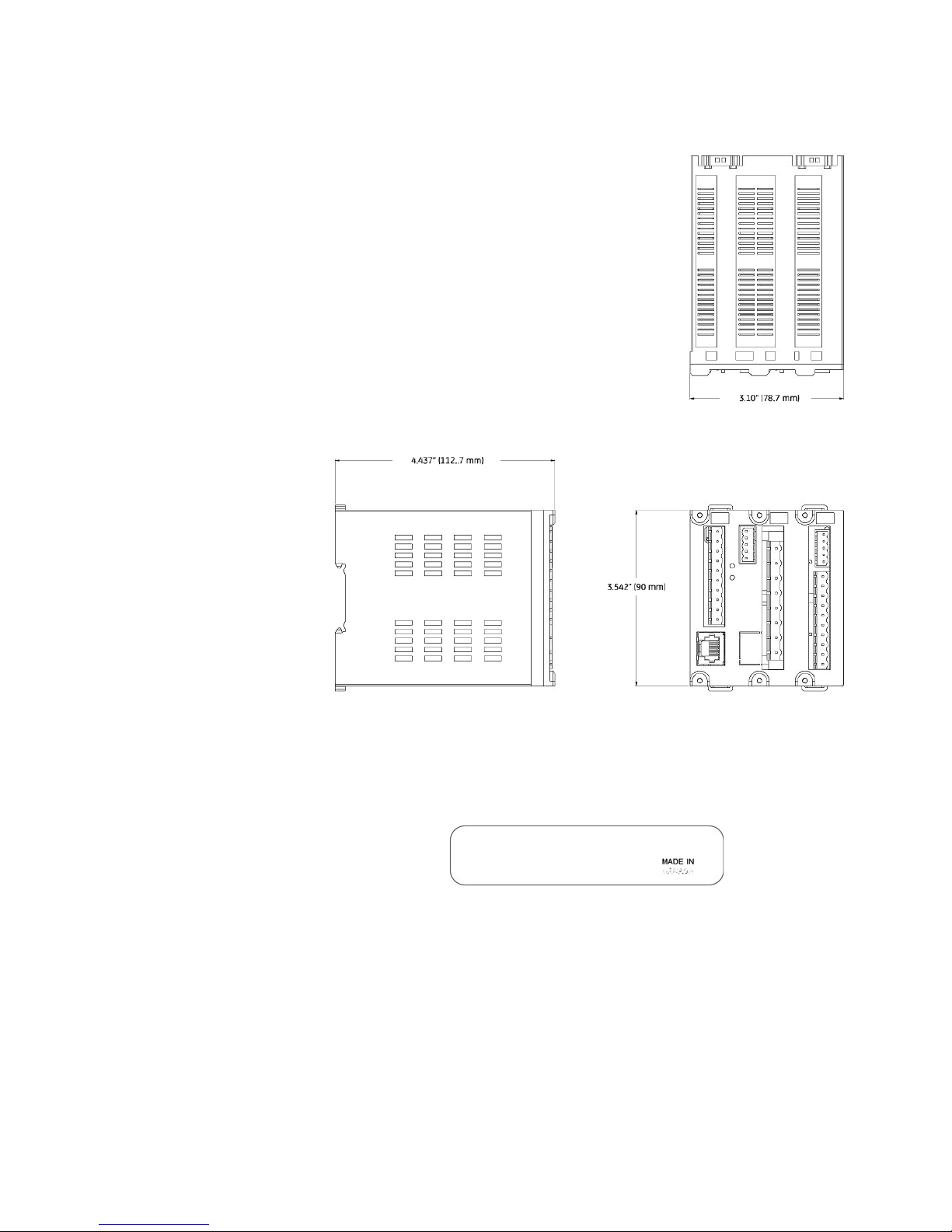
Mechanical installation..................................................................................................................................2
Dimensions ......................................................................................................................................................... 2
Product identification..................................................................................................................................... 3
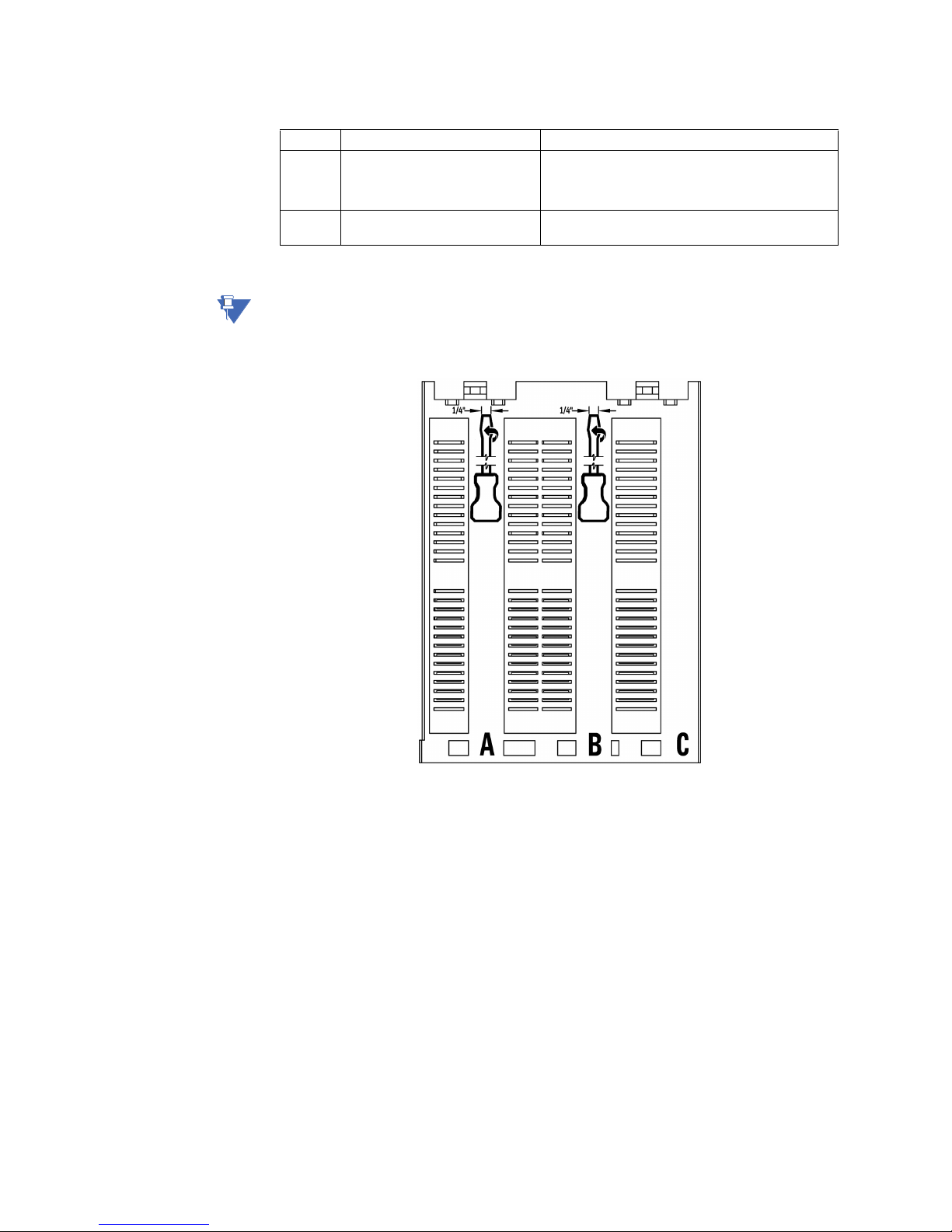
Mounting.............................................................................................................................................................. 4
Electrical installation.......................................................................................................................................5
Full-voltage non-reversing starter........................................................................................................... 9
RS485 connections .......................................................................................................................................10
Control panel...................................................................................................................................................11
Basic control panel .......................................................................................................................................11
Setpoints ........................................................................................................................13
Understanding setpoints ........................................................................................................................... 13
Configuration setpoints..............................................................................................................................13
Motor setpoints...............................................................................................................................................13
Common motor setpoints..........................................................................................................................13
Current transformers ...................................................................................................................................15
Protection elements.....................................................................................................16
Thermal protection....................................................................................................................................... 16
Overload curve................................................................................................................................................16
Communications interfaces .......................................................................................19
Specifications................................................................................................................20
Protection specifications ...........................................................................................................................20
Inputs specifications .................................................................................................................................... 21
Outputs specifications ................................................................................................................................22
Power supply specifications.....................................................................................................................22
Communications specifications.............................................................................................................22
Testing and certification ............................................................................................................................23
Physical specifications................................................................................................................................23
Environmental specifications .................................................................................................................. 24
MM200 order codes......................................................................................................25
Example of an MM200 order code........................................................................................................25
INDEX
SUMMARY OF CERTIFICATION

toc–2 MM200 MOTOR MANAGEMENT SYSTEM – QUICKSTART GUIDE
TABLE OF CONTENTS

MM200 MOTOR MANAGEMENT SYSTEM – QUICKSTART GUIDE 1
MM200 Motor Management System
QuickStart Guide
Digital Energy
Multilin
QuickStart Guide
1.1 Overview
The MM200 is a motor protection and control system designed specifically for low-voltage
motor applications. The MM200 provides the following key benefits.
• Protection, control, and communication options to suit low-voltage motor
applications.
• Small footprint designed specifically for IEC and NEMA MCC applications.
• DIN rail Mounting.
• Multiple communication protocols allows simple integration into monitoring and
control systems.
• Optional basic control panel interface provides local control and access to system
information.

2MM200 MOTOR MANAGEMENT SYSTEM – QUICKSTART GUIDE
OVERVIEW QUICKSTART GUIDE
Figure 1: Single line diagram
Table 1: MM200 protection functions
1.1.1 Mechanical installation
This section describes the mechanical installation of the MM200 system, including
dimensions for mounting.
1.1.1.1 Dimensions
The MM200 is packaged in a fixed format divided into three specific sections.
The dimensions of the MM200 are shown below. Additional dimensions for mounting are
shown in the following sections.
RS485 - Modbus RTU
Profibus/DeviceNet
52
METERING
A
51R 49 37 46
50G
MOTOR
LOAD
Temperature
Thermistor
Phase CT 3
Ground CT 1
Power Fuse
BUS
MM200
MOTOR MANAGEMENT SYSTEM
Contactor
888739A2.CDR
LO: 7 inputs and 3 outputs
HI: 6 inputs and 3 outputs
LO:24VDC
HI:84to250VDC/60to300VAC
ANSI device Description
37 Undercurrent and underpower
46 Current unbalance
49 Thermal overload
50G Ground instantaneous overcurrent
51R Locked/stalled rotor, mechanical jam

QUICKSTART GUIDE OVERVIEW
MM200 MOTOR MANAGEMENT SYSTEM – QUICKSTART GUIDE 3
Figure 2: MM200 dimensions
1.1.1.2 Product identification
The product identification label is located on the side panel of the MM200. This label
indicates the product model, serial number, firmware revision, and date of manufacture.
Figure 3: MM200 Identification label
888748A1.CDR
Model:
Serial Number:
Firmware: Mfg.Date:

4MM200 MOTOR MANAGEMENT SYSTEM – QUICKSTART GUIDE
OVERVIEW QUICKSTART GUIDE
Figure 4: MM200 ratings label
1.1.1.3 Mounting
The MM200 is DIN rail mounted.
The standard DIN rail mounting is illustrated below. The DIN rail conforms to EN 50022.
CAUTION
CAUTION: To avoid the potential for personal injury due to fire hazards, ensure the unit is
mounted in a safe location and/or within an appropriate enclosure.
Figure 5: DIN rail mounting
1.1.2 Electrical installation
This section describes the electrical installation of the MM200 system. An overview of the
MM200 terminal connections is shown below.

QUICKSTART GUIDE OVERVIEW
MM200 MOTOR MANAGEMENT SYSTEM – QUICKSTART GUIDE 5
CAUTION
CAUTION: MM200 is not to be used in any way other than described in this manual.
Figure 6: MM200 terminal connection overview
A Modbus RTU RS485 port, a thermistor input, and a 50:0.025 CBCT input are provided.
Profibus and Devicenet are provided as options.
Table 2: Slot position
Figure 7: MM200 terminal connection torque rating
CAUTION
CAUTION: Use gauge size appropriate for the voltage and current draw of the device.
Slot Type
A PSU/Inputs/Control Panel
BCPU/CTs
C Outputs/CBCT/Thermistor/RS485
Control Panel
Profibus or DeviceNet
Optional fieldbus protocols
888740A2.CDR
CTs
PSU
Inputs
RS485
Thermistor
CBCT
2 x Form A
1 x Form C
connector screw torque
CT 4.5 lb-in
IPS, output 5.0 lb-in
Fieldbus, 3.0 lb-in
Thermistor & RS485

6MM200 MOTOR MANAGEMENT SYSTEM – QUICKSTART GUIDE
OVERVIEW QUICKSTART GUIDE
Table 3: Wire Gauge Sizes
NOTE
NOTE: It is recommended that you install a circuit disconnection system for control power, near
the device, which should be easily accessible after installation of the unit. This is in case an
emergency power shut-down of the unit is required.
Figure 8: Top and Rear panel arrangement
The MM200 I/O terminals are labeled with a two-character identifier. The first character
identifies slot position and the second identifies the terminal.
Slot A PSU and Inputs 12 AWG (2.5 mm2) (5.00mm pitch terminals)1
1.Wire gauge size remains constant; increased pitch distance reflects higher voltage rating.
Slot B Fieldbus,
CT Connections
16 AWG (1.5 mm2) (3.50mm pitch terminals)12 AWG
(2.5 mm2) (7.62mm pitch terminals)1
Slot C RS485 & ThermistorOutput Relays,
CBCT 16 AWG (1.5 mm2) (3.50mm pitch terminals12 AWG
(2.5 mm2) (5.00mm pitch terminals)1

QUICKSTART GUIDE OVERVIEW
MM200 MOTOR MANAGEMENT SYSTEM – QUICKSTART GUIDE 7
CAUTION
CAUTION: Check the voltage rating of the unit before applying control power! Control power
outside of the operating range of the power supply will damage the MM200.
Figure 9: CBCT ground CT connection
HI
LO
888351A3-P2
888741A3.CDR
A
C
B
Contactor
Contactor
TO
CONTROL
PANEL
C1
C2
C4
C3
C5
C6
MM200
Motor Management System
C8
C9
C10
C7
Two form-A
contact outputs
CONTACT OUTPUT 2
One form-C
contact output
CONTACT OUTPUT 1
CONTACT OUTPUT 3
THERMISTOR
CBCT
RS485
R
I
-
+
-
+
C
B3 B4 B5 B6 B7 B8
IRIRIR
CT1 CT2 CT3
CT MODULE
RJ45
PROFIBUS OR DEVICENET
V- LHV+
MOTOR
M
M
SG
LO and HI inputs
- see below -

8MM200 MOTOR MANAGEMENT SYSTEM – QUICKSTART GUIDE
OVERVIEW QUICKSTART GUIDE
Figure 10: CBCT ground CT connection - LO and HI inputs
The exact placement of a zero-sequence CT to detect only ground fault current is shown
below. If the core balance CT is placed over shielded cable, capacitive coupling of phase
current into the cable shield during motor starts may be detected as ground current unless
the shield wire is also passed through the CT window. Twisted-pair cabling on the zero-
sequence CT is recommended.
Figure 11: Core balance ground CT installation, shielded cable
M
-
+
A1
A2
A4
A3
A5
A6
A8
A9
A10
A7
+
-
24 VDC CONTACT INPUTS
CONTROL
POWER (VDC)
CONTROL
POWER
24 VDC
FIELD STOP
FIELD START
RESET
M
N
L
A1
A2
A4
A3
A5
A6
A8
A9
A10
L
N
VAC CONTACT INPUTS
CONTROL
POWER (VAC)
CONTROL
POWER
VAC
FIELD STOP
FIELD START
RESET
NR
LO HI
888742A1.cdr
RETURN
NOTE: AC power and AC input wiring shown.
Connect NR to Neutral if DC power supply used.
POWER CABLE
TO MOTOR
TO STARTER
GROUND BUS
CABLE LUGS
TO SOURCE
TERMINATION
(TWISTED PAIR)
SPLIT-BOLT CONNECTOR
888712A1.CDR
CORE BALANCE CT
SECONDARY CONNECTION
TO MM200 IED
IMPORTANT: FOR SHIELDED
CABLE, THE GROUND WIRE
MUST PASS THROUGH THE
CT WINDOW.
50:0.025 CORE BALANCE CT
FOR GROUND SENSING
STRESS CONE
SHIELD GROUND
CONNECTION
BOTTOM OF
MOTOR STARTER
COMPARTMENT

QUICKSTART GUIDE OVERVIEW
MM200 MOTOR MANAGEMENT SYSTEM – QUICKSTART GUIDE 9
Figure 12: Core balance ground CT installation, unshielded cable
1.1.2.1 Full-voltage non-reversing starter
Figure 13: Full-voltage non-reversing starter wiring
POWER CABLE
TO MOTOR
50:0.025 CORE BALANCE CT
FOR GROUND CT SENSING
TO STARTER
GROUND BUS
CABLE LUGS TO SOURCE
TERMINATION
(TWISTED-PAIR)
888713A1.CDR
GROUND CONDUCTOR DOES
NOT PASS THROUGH CT, AS THE
CT IS NOT MOUNTED OVER
GROUND WITHIN THE CABLE
JACKET.
BOTTOM OF
MOTOR STARTER
COMPARTMENT
CORE BALANCE CT
SECONDARY CONNECTION
TO MM200 IED
888741A3.CDR
A
C
B
Contactor
Contactor
TO
CONTROL
PANEL
C1
C2
C4
C3
C5
C6
MM200
Motor Management System
C8
C9
C10
C7
Two form-A
contact outputs
CONTACT OUTPUT 2
One form-C
contact output
CONTACT OUTPUT 1
CONTACT OUTPUT 3
THERMISTOR
CBCT
RS485
R
I
-
+
-
+
C
B3 B4 B5 B6 B7 B8
IRIRIR
CT1 CT2 CT3
CT MODULE
RJ45
PROFIBUS OR DEVICENET
V- LHV+
MOTOR
M
M
SG
LO and HI inputs
- see below -

10 MM200 MOTOR MANAGEMENT SYSTEM – QUICKSTART GUIDE
OVERVIEW QUICKSTART GUIDE
Figure 14: LO and HI inputs
The full-voltage non-reversing starter type is a full voltage or across-the-line non-reversing
starter.
When a start control is received, the pre-contactor relay (if any) is picked up for the set pre-
contactor time. When the pre-contactor timer times out, relay contact output 1 closes and
seals-in, picking up contactor M, which starts the motor. When a stop control is received,
relay contact output 1 drops out, contactor M drops out, and the motor stops. The pre-
contactor is omitted on forced starts (for example, External Start).
1.1.2.2 RS485 connections
Figure 15: Typical RS485 connection
One two-wire RS485 port is provided. Up to 32 MM200 IEDs can be daisy-chained together
on a communication channel without exceeding the driver capability. For larger systems,
additional serial channels must be added. Commercially available repeaters can also be
M
-
+
A1
A2
A4
A3
A5
A6
A8
A9
A10
A7
+
-
24 VDC CONTACT INPUTS
CONTROL
POWER (VDC)
CONTROL
POWER
24 VDC
FIELD STOP
FIELD START
RESET
M
N
L
A1
A2
A4
A3
A5
A6
A8
A9
A10
L
N
VAC CONTACT INPUTS
CONTROL
POWER (VAC)
CONTROL
POWER
VAC
FIELD STOP
FIELD START
RESET
NR
LO HI
888742A1.cdr
RETURN
NOTE: AC power and AC input wiring shown.
Connect NR to Neutral if DC power supply used.
SCADA, PLC, OR
PERSONAL COMPUTER
COM
OPTOCOUPLER
DATA
MM200 IED
SHIELD
888745A1.CDR
UP TO 32 MM200
OR OTHER IEDs,
MAXIMUM CABLE
LENGTH OF
1200 m (4000 ft.)
LAST
DEVICE
(*) TERMINATING IMPEDANCE AT EACH END
(typically 120 ohms and 1 nF)
TWISTED PAIR
ZT(*)
RS485 +
RS485 -
COMMON
RS485 +
RS485 -
COMMON
IED
RS485 +
IED
RS485 -
COMMON
GROUND THE SHIELD AT THE
SCADA/PLC/COMPUTER ONLY
OR THE MM200 ONLY
DATA
OPTOCOUPLER
ZT(*)
+
-
C

QUICKSTART GUIDE OVERVIEW
MM200 MOTOR MANAGEMENT SYSTEM – QUICKSTART GUIDE 11
used to add more than 32 relays on a single channel. Suitable cable should have a
characteristic impedance of 120 ohms (for example, Belden #9841) and total wire length
should not exceed 1200 meters (4000 ft.). Commercially available repeaters will allow for
transmission distances greater than 1200 meters.
Voltage differences between remote ends of the communication link are not uncommon.
For this reason, surge protection devices are internally installed across all RS485 terminals.
Internally, an isolated power supply with an optocoupled data interface is used to prevent
noise coupling.
CAUTION
CAUTION: To ensure that all devices in a daisy-chain are at the same potential, it is imperative
that the common terminals of each RS485 port are tied together and grounded only
once, at the master or at the MM200. Failure to do so may result in intermittent or
failed communications.
The source computer/PLC/SCADA system should have similar transient protection devices
installed, either internally or externally. Ground the shield at one point only, as shown in the
figure above, to avoid ground loops.
Correct polarity is also essential. The MM200 IEDs must be wired with all the positive (+)
terminals connected together and all the negative (–) terminals connected together. Each
relay must be daisy-chained to the next one. Avoid star or stub connected configurations.
The last device at each end of the daisy-chain should be terminated with a 120 ohm
¼ watt resistor in series with a 1 nF capacitor across the positive and negative terminals.
Observing these guidelines will ensure a reliable communication system immune to
system transients.
1.1.3 Control panel
This section provides an overview of the interfacing methods available with the MM200.
For additional details on interface parameters (for example, settings, actual values, etc.),
refer to the individual chapters.
There are two methods of interfacing with the MM200 Motor Management System.
• Via the basic control panel.
• Via the EnerVista MM200 Setup software.
NOTE
NOTE: For full details on handling the EnerVista MM200 Setup software, please use the EnerVista
MM200 Setup Software Guide which accompanies this manual.
1.1.3.1 Basic control panel
The MM200 basic control panel provides the basic start and stop panel functionality, as
well as a series of LED indications. The basic control panel is illustrated below.

12 MM200 MOTOR MANAGEMENT SYSTEM – QUICKSTART GUIDE
OVERVIEW QUICKSTART GUIDE
Figure 16: Basic control panel
The following LEDs are provided:
• Two USER LEDs (USER 1 and USER 2). the user can select parameters from a list
• 50%/80%/100% - showing motor load
• RUNNING, STOPPED, TRIPPED, and ALARM
• COMMS OK
•AUTOandMANUAL
888750A1.CDR

QUICKSTART GUIDE SETPOINTS
MM200 MOTOR MANAGEMENT SYSTEM – QUICKSTART GUIDE 13
1.2 Setpoints
1.2.1 Understanding setpoints
Setpoints can be modified via RS485, using the EnerVista MM200 Setup program.
CAUTION
CAUTION: Setpoints may be changed while the motor is running; however it is not recommended
to change important protection parameters without first stopping the motor.
Setpoints will remain stored indefinitely in the internal non-volatile memory even when
control power to the unit is removed. Protection parameters are based on the entered
data. This data must be complete and accurate for the given system for reliable protection
and operation of the motor.
1.2.2 Configuration setpoints
The configuration setpoints contains data on motor configuration as well as system setup,
inputs, outputs, communications, and CTs.
• Motor (setpoints related to motor configuration).
• CT (setpoints related to CT configuration).
• Inputs (setpoints related to digital input configuration)
• Outputs (setpoints related to digital output configuration)
• Comms (setpoints related to communications configuration)
• System (setpoints related to MM200 system configuration, such as the faceplate LEDs)
• Counters (setpoints related to the digital counters)
1.2.2.1 Motor setpoints
The MM200 starter function is responsible for executing the motor startup sequence,
including the pre-contactor start warning. The MM200 provides three pre-defined starters.
• Full-voltage non-reversing
• Full-voltage reversing
• Two-speed
NOTE
NOTE: By selecting a pre-defined starter, inputs and outputs are automatically assigned.
1.2.2.2 Common motor setpoints
Several motor setpoints are dependent on the chosen starter type. The setpoints shown
below are common to all starter types.
Motor Name
Range: up to 20 alphanumeric characters
Default: Motor Name
This setpoint specifies a name for the motor. This name will appear in the actual values.
Starter Type (Mandatory setpoint)
Range: None, FV Non-Reversing, FV Reversing, Two Speed
Default: FV Non-Reversing
This setpoint selects the starter type. The relay is essentially disabled when the value is
set to “None”. Figure 1 illustrates typical starter timing beginning from the stopped state
for all starter types.

14 MM200 MOTOR MANAGEMENT SYSTEM – QUICKSTART GUIDE
SETPOINTS QUICKSTART GUIDE
Motor FLA (Mandatory setpoint)
Range: 0.5 to 1000.0 amps in steps of 0.1
Default: OFF
This setpoint must be specified for motor protection. The value may be taken from the
motor nameplate data sheets.
Supply Frequency (Mandatory setpoint)
Range: 50 Hz, 60 Hz
Default: 60 Hz
This setpoint specifies the nominal system frequency.
Motor Rating (Mandatory setpoint)
Range: 0.3 to 1100.0 kW in steps of 0.1 or OFF
Default: OFF
This setpoint specifies the motor rating (or low speed motor rating for two-speed
starters) in kWs.
The following sections provide additional information for each starter type.
Figure 17: Typical starter timing
1.2.2.3 Current transformers
The following setpoints are available to configure the current and voltage transformers.
Contactor B Relay
Contactor A Relay
Pre-contactor
Starting
Running
Start A
Start B
Start A
Stop
Motor Current
Full Voltage Non-reversing
Contactor B Relay
Contactor A Relay
Pre-contactor
Starting
Running
Motor Current
Full Voltage Reversing
Contactor B Relay
Contactor A Relay
Pre-contactor
Starting
Running
Motor Current
Two Speed Starter
P
T
P
P
T
T
P - Pre-contactor Time setting
T - Transfer Time setting
R - Ramp Down Time setting
888710A1.CDR

QUICKSTART GUIDE SETPOINTS
MM200 MOTOR MANAGEMENT SYSTEM – QUICKSTART GUIDE 15
Phase CT Type (Mandatory setpoint)
Range: None, 1 A Secondary, 5 A Secondary, Direct Connect
Default: Direct Connect
This setpoint specifies the phase CT connection type. The “Direct Connect” value
indicates that no phase CTs are used; instead, motor phase current passes directly
through the relay. The “Direct Connect” selection should never be used where full load
current is greater than 5.0 amps.
NOTE
NOTE: If Direct Connect is selected and the FLA is set >5 A, a "FLA too high" message will be
displayed on the Status page.
CT Primary Turns
Range: 1 to 10
Default: 1
For smaller motors where the drawn current is very low, the motor leads may be
wrapped through the CT Primary with several turns thereby increasing the current seen
by the MM200 and as a result increasing the accuracy of the measurement. The value of
this setting should equal the number of turns on the CT Primary to display the correct
current value. Internally the current measurement will be divided by this setting.
CT Primary (Mandatory setpoint)
Range: 5 to 1000 amps in steps of 1
Default: 5 amps
This setpoint specifies the phase CT primary current. It should never be less than the full
load current, and preferably no greater than twice than the full load current.
NOTE
NOTE: This setpoint is displayed only if the phase CT is selected to 1 A secondary or 5 A
secondary.
High Speed CT Primary
Range: 5 to 1000 amps in steps of 1
Default: 5 amps
This setpoint specifies the phase CT primary current when the motor is running at high
speed. It should never be less than the high speed full load current, and preferably no
greater than twice than the high speed full load current.
NOTE
NOTE: This setpoint is displayed only if the phase CT is selected as 1 A secondary or 5 A
secondary and the motor starter type is two-speed.

16 MM200 MOTOR MANAGEMENT SYSTEM – QUICKSTART GUIDE
PROTECTION ELEMENTS QUICKSTART GUIDE
1.3 Protection elements
1.3.1 Thermal protection
The primary protective function of the MM200 is the thermal model. The MM200 integrates
stator and rotor heating into a single model. The rate of motor heating is gauged by
measuring the terminal currents. The present value of the accumulated motor heating is
maintained in the Thermal Capacity Used actual value register. When the motor is in
overload, the motor temperature and thermal capacity used will rise. A trip occurs when
the thermal capacity used reaches 100%. When the motor is stopped and is cooling to
ambient, the thermal capacity used decays to zero. If the motor is running normally, the
motor temperature will eventually stabilize at some steady state temperature, and the
thermal capacity used increases or decreases to some corresponding intermediate value,
which accounts for the reduced amount of thermal capacity left to accommodate
transient overloads.
The thermal model consists of four key elements.
• Hot/cold biasing that accounts for normal temperature rise.
• An overload curve that accounts for the rapid heating that occurs during stall,
acceleration, and overload.
• Cooling rate that accounts for heat dissipation.
• Thermal protection reset that controls recovery from thermal trips and lockouts.
Each of these categories are described in the following sub-sections.
1.3.1.1 Overload curve
The overload curve accounts for the rapid motor heating that occurs during stall,
acceleration, and overload. Specifically, the overload curve controls the rate of increase of
Thermal Capacity Used whenever the equivalent motor heating current is greater than
1.01 times the full load current setpoint. The curve is defined by the following equation and
reflects that overload heating largely swamps the cooling, and this heating is primarily due
to resistive losses in the stator and the rotor windings (said losses being proportional to the
square of the current).
Eq. 1
Eq. 2
In the above equation,
• The trip time represents the time (in seconds) for the MM200 to trip, given the motor
starts cold and the current is constant.
• The multiplier represents the value of the Curve Multiplier setpoint. This setpoint can
be used to adjust the curve to match the thermal characteristics of the motor.
•Iav represents the equivalent motor heating current in per-unit values on a full load
current base. The value of Iav is limited in this equation to 8.0 to prevent the overload
from acting as an instantaneous element and responding to short circuits.
=IAV
Pickup FLA
´
=Curve Multiplier
timeTrip
2.2116623
0.02530337 x (Pickup - 1) + 0.05054758 x (Pickup -1)
2
Other manuals for MM200
1
Table of contents
Other GE Multilin Protection Device manuals
Popular Protection Device manuals by other brands

Smart power
Smart power Smart Cord Plus user guide

Deister electronic
Deister electronic proxSafe flexx Wiring & installation instructions

Palmer Safety
Palmer Safety C0850 User instructions

Hunter
Hunter A2 user manual

MULTISPAN
MULTISPAN MPD-19EL-M1 manual

Trend Micro
Trend Micro TippingPoint TPS TX Series Hardware Specification and Installation Guide