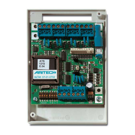
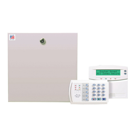
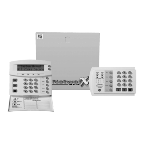
GE ATS4000 Operating instructions

ATS2000/3000/4000/4500
Control Panel
Quick Programming Guide
Version 2.0, August 2003
Intelligent Security & Fire Ltd

A
ritech is a GE Interlogix brand.
www.GE-Interlogix.com
Copyright
(c) 2003 GE Interlogix B.V.. All rights reserved. GE Interlogix B.V. grants the right to reprint this manual for internal use only. GE
Interlogix B.V. reserves the right to change information without notice.
Intelligent Security & Fire Ltd

ATS2000/3000/4000/4500 Quick Programming Guide
3
CONTENTS
Contents ............................................................................................................................................................3
1. Quick Programming Guide....................................................................................................................4
1. Defaulting the panel to factory defaults (using the ‘Kill’ jumper) ....................................................4
2. Powering up the panel ...................................................................................................................4
3. Disarming the system.....................................................................................................................4
4. Defaulting the panel to factory defaults (using Menu 14) ..............................................................4
5. Entering the ATS menu..................................................................................................................4
6. Entering the programming menu to program the system ..............................................................4
7. Changing parameters in the programming (examples) .................................................................5
Programming zones ......................................................................................................................5
Change manager code..................................................................................................................5
8. Programming sequences ...............................................................................................................5
2. Programming Map..................................................................................................................................6
Intelligent Security & Fire Ltd

ATS2000/3000/4000/4500 Quick Programming Guide
4
1. QUICK PROGRAMMING GUIDE
1. Defaulting the panel to factory
defaults (using the ‘Kill’ jumper)
When installed, the control panel needs to be defaulted
to factory defaults. This option resets all programming to
the factory default. All programming will be erased and
all options will have the standard values. (Real time
clock will be reset).
Follow the next steps:
1. Remove all power to the control panel (mains and
battery)
2. Shorten the “KILL” jumper
3. Wait 30 seconds
4. Open the “KILL” jumper
The panel is now back to factory defaults.
2. Powering up the panel
On the initial power-up:
• The ATS control panel LED’s should indicate:
L1 - Slow flashing
Comms Tx - Rapid flashing
Comms Rx - Rapid flashing (If RAS 1 connected
and functional)
• The Master LCD Arming Station (RAS 1) should
have all area LED ON and the LCD should display
the name "Aritech Systems" followed by details of
the Arming Station software version.
A LCD RAS will also prompt you to Press the [MENU*]
key.
Press the [MENU*] key followed by [ENTER]. The
normal LCD display message shown below appears:
If there is a system condition, it is displayed on the top
line.
If the Master RAS powers up with no LED ON and there
is no LCD display, then no power has been applied to
the RAS. If the Master RAS powers up with all the LED
flashing, the LCD reads "System Fault" and the control
panel conditions as described above are correct, then:
The system databus cabling must be faulty, or
The Arming Station address has been incorrectly set
(RAS 1 = All dipswitches OFF).
3. Disarming the system
You must disarm the system before you can use the
Installer Menu.
To disarm the system
Press 1 1 2 2 (Manager PIN code), [OFF] followed by 0
(select all areas) and then [ENTER].
If you are unable to disarm the system using the
Manager PIN Code and the [OFF] key, then you might
need to default the panel.
4. Defaulting the panel to factory
defaults (using Menu 14)
99-ALL – This option resets all programming to the
factory default. All programming will be erased and all
options will have the standard values. (Real time clock
will not be affected).
For other options refer to the ATS2000/3000/4000/4500
programming guide
To default the panel programming settings
1. Enter [Menu*] 1 2 7 8 and press [ENTER] to access
the ATS menu.
2. Press 19 [ENTER] to access the programming
menu. The following display appears:
3. Press * to access the Advanced Menu
4. Press 14 [ENTER] to access the Default menu
5. Press 99 [ENTER]. Panel is now defaulted.
5. Entering the ATS menu
Enter [Menu*] 1 2 7 8 and press [ENTER]. The following
display appears:
You can now enter the desired menu number.
See the programming and manager guide
6. Entering the programming menu to
program the system
To enter to the programming menu
1. Press [MENU*] 1 2 7 8 and press [ENTER] to
access the ATS menu.
2. Press 19 and [ENTER] to access the programming
menu. The following display appears:
0-Exit, ENTER-Down, *-Up
0-Exit, Menu:
Simple/Advanced Menu
* - Advanced
There Are No Alarms In This Area
Code:
E
a
r
t
hL
ug
J17-PowerSystemearth(seedetailspage4)12Vbattery.
J14-AuxiliarypowerJ13Sirens/StrobeConnectionExternal8Ohmsirenspeakerorsirene
1Kresistormustbefittedifexternalsirennotconnected.Internal8Ohmsirenspeaker12VstrobeJ3-Commsandpaneltamperwiring
SystemdatabusNormallyclosedfrontpaneltampercontactNormallyclosedrearpaneltampercontact
J9-BellJ2toJ6ZonewiringNormallyClosedAlarmContact
NormallyClosedTampercontactJ7ATS1202ZoneexpansionJ8-CLKOUT(ATS1810/1820)
+12VOutputboardJ11Computer/printerexpansionJ18Serialconnection(RS232)
J20ISDN/AudioInterfaceJ15/J19RJ45PTTconnector(notfitted)J16PSTNLineconnection
EPROM(factoryfitted)Flash/RAMorIUM(optional)ISP.Circuitprogrammingconnector,usedtoprogramtheCPLD(factoryused)
Test1UseforresettingtheMasterEngineercode.Test2FactoryuseonlyTobeusedforATS1202(onlywithATS3000)
J6
1
C
2
C
3
C
?
S+S-S+S-+-
1211
J
1
0
TH1TH3TH5TH2TH4
NEGCPOS
J5
4
C
5
C
6
C
J
4
7
C
8
C
9
C
J3
1
0
C
11
C
12
C
J
2
1
3
C
14
C
1
5
C
1
6
C
J11
J
7
R
A
M
/
I
U
M
FL
AS
HEPR
O
M
ABAXBXEA
J
1
5
J
1
9
J
1
6
J
1
8
J
2
0
TST1TST2
+12V
9
-1
6
I
S
P
KILL
12VRXTX
0
V
1413
15
J9
30
161
6
1
6
1
6
1
6
1717
1
8
1
9
2
3
24
2
5
2
6
272
8
29
3
1
3
2
33
34
2
5
2
8
J
17
J
14
J
1
3
J8
T
e
m
po
r
a
r
y
se
rvi
ce
co
nn
ect
i
o
n-
se
ri
a
lP
o
r
t
(J
1P
C
Co
nn
ec
ATS3000/4000J18DB25Db9
12VRX.............................TX23TX.............................RX32
0V..............................GND75
1011
121314
151617
181920
212223
242526
272829
303132
3334
2
345
67
1
8
9
22
Kill-F
acto
r
y
de
f
au
l
t
co
n
t
r
o
l
pa
n
e
lwh
e
n
s
h
o
r
ted
TransformerACconnection
E
a
r
t
hL
ug
J17-PowerSystemearth(seedetailspage4)12Vbattery.
J14-AuxiliarypowerJ13Sirens/StrobeConnectionExternal8Ohmsirenspeakerorsirene
1Kresistormustbefittedifexternalsirennotconnected.Internal8Ohmsirenspeaker12VstrobeJ3-Commsandpaneltamperwiring
SystemdatabusNormallyclosedfrontpaneltampercontactNormallyclosedrearpaneltampercontact
J9-BellJ2toJ6ZonewiringNormallyClosedAlarmContact
NormallyClosedTampercontactJ7ATS1202ZoneexpansionJ8-CLKOUT(ATS1810/1820)
+12VOutputboardJ11Computer/printerexpansionJ18Serialconnection(RS232)
J20ISDN/AudioInterfaceJ15/J19RJ45PTTconnector(notfitted)J16PSTNLineconnection
EPROM(factoryfitted)Flash/RAMorIUM(optional)ISP.Circuitprogrammingconnector,usedtoprogramtheCPLD(factoryused)
Test1UseforresettingtheMasterEngineercode.Test2FactoryuseonlyTobeusedforATS1202(onlywithATS3000)
J6
1
C
2
C
3
C
?
S+S-S+S-+-
1211
J
1
0
TH1TH3TH5TH2TH4
NEGCPOS
J5
4
C
5
C
6
C
J
4
7
C
8
C
9
C
J3
1
0
C
11
C
12
C
J
2
1
3
C
14
C
1
5
C
1
6
C
J11
J
7
R
A
M
/
I
U
M
FL
AS
HEPR
O
M
ABAXBXEA
J
1
5
J
1
9
J
1
6
J
1
8
J
2
0
TST1TST2
+12V
9
-1
6
I
S
P
KILL
12VRXTX
0
V
1413
15
J9
30
161
6
1
6
1
6
1
6
1717
1
8
1
9
2
3
24
2
5
2
6
272
8
29
3
1
3
2
33
34
2
5
2
8
J
17
J
14
J
1
3
J8
T
e
m
po
r
a
r
y
se
rvi
ce
co
nn
ect
i
o
n-
se
ri
a
lP
o
r
t
(J
1P
C
Co
nn
ec
ATS3000/4000J18DB25Db9
12VRX.............................TX23TX.............................RX32
0V..............................GND75
1011
121314
151617
181920
212223
242526
272829
303132
3334
2
345
67
1
8
9
22
Kill-F
acto
r
y
de
f
au
l
t
co
n
t
r
o
l
pa
n
e
lwh
e
n
s
h
o
r
ted
TransformerACconnection
Simple/Advanced Menu
* - Advanced
Intelligent Security & Fire Ltd

ATS2000/3000/4000/4500 Quick Programming Guide
5
3. Press [ENTER] to access the Simple Menu (or
press * to access the Advanced Menu) The
following display appears:
Before programming the system, for the first time, you
must default the settings.
You can now select the option you want to program.
7. Changing parameters in the
programming (examples)
Programming zones
This function is used to program information relating to
an individual zone.
This step determines how the zones will function in given
circumstances.
There are over 50 types of zones. Refer to section 1 of
the programming guide for further information.
To program the zones
1. Enter [Menu*] and the Master Engineer code. Press
[ENTER].
2. Press 19 [ENTER] to access the programming menu
3. Press [ENTER] to access the Simple Menu
4. Press 1 [ENTER] to access the Zone Database
menu
5. Press zone number [ENTER] to access details of
the zone to be programmed and press [ENTER]
again to move to the next zone database display, or
Press [ENTER] to return to the programming menu.
Notes:
ATS2000 only allows for:
- 32 zones not being programmed with zone
type 0 (not used).
- Assigning areas 1-4 to zones.
ATS3000 only allows for:
- 64 zones not being programmed with zone
type 0 (not used).
- assigning areas 1-8 to zones.
ATS4000 only allows for:
-256 zones not being programmed with zone
type 0 (not used).
- assigning areas 1-16 to zones.
Change manager code
Press [Menu*] and enter the Manager PIN code
(1122). Press [ENTER].
1. Press 14 [ENTER] for access to program users
2. Press 3 [ENTER] (Create user).
3. Press 1 [ENTER] (Create user 1).
4. Press [ENTER] three times and then press [MENU*]
to keep the same name.
5. Enter the new code (up to 10 digits) and press
[ENTER].
6. Press Clear to exit. The Manager code is now
changed.
8. Programming sequences
The following can be used as a guide for the order
in which records can be programmed when setting
up a basic system.
1. Draw the floor plan and label all zones, equipment,
areas etc. Use programming sheets to fill out all
information
2. Default the control panel, change the Master
Engineer Code and set the time and date
3. Program specific words which are not in the library
4. Program the timezones
5. Program the areas
6. Program the alarm groups
7. Program the RAS and DGP
8. Program the zones
9. Program the dialler
10. Program users
11. Program outputs.
Installer Programming
0-Exit, Menu:
Intelligent Security & Fire Ltd

6ATS2000/3000/4000/4500 Quick Programming Guide
2. PROGRAMMING MAP
1. Zone Database 1. Zone number
Zone Type
1. Zone name
2. Zone type
3. Reporting of zone
6. Report alarm to CS 3
4. Report alarm to CS 1
5. Report alarm to CS 2
7. Report alarm to CS 4
8. Enable ALI for this zone
9. Enable engineer reset for alarms
10. Enable engineer reset for tampers
13. Area / alarm group assignment
11. Disable inhibit of the zone
12. Enable Soak Test
14. Test option
15. Zone event flag
16. Internal Siren Event flag
17. External Siren Event flag
20. Trigger event flag 2, armed alarm
18. Keypad Buzzer
19. Make all events 24 hour
21. Trigger event flag 3, armed alarm
22. Trigger event flag 4, armed alarm
23. Trigger event flag 5, armed alarm
24. Trigger event flag 6, armed alarm
27. Trigger event flag 9, 24hr alarm
25. Trigger event flag 7, disarmed alarm
26. Trigger event flag 8, disarmed alarm
28. Trigger event flag 10, armed alarm
31. Trigger camera event in area DB
29. Trigger event flag 11, armed alarm
30. Trigger zone event flag when active
32. Print zone when active
Simple
/Advanced Menu
*-Advanced
Simple menus
Advanced menus
Legend
27. Technical with Report
28. Armed Alarm with reset
29. 24 Hour Alarm with reset
30. Fire door with reset
31. Latching keyswitch
32. Armed zone to event flag
33. 24 hr Alarm and Inhibit
34. Area Dis/Almgrp restr. Arm
35. Area Almgrp restr. Arm Only
36. Camera 5 count
37. Camera 6 count
38. Camera 7 count
39. Camera 8 count
40. Dis. Susp.Delay /Arm Alm
41. Entry/Exit Fire door
42. Entry/Exit Fire Door w. code
43. Disarm zone to Event Flag
44. Fire door with almgrp restr.
45. (Event flag/Arm.Alm) Almgrp.
restr.
46. Disarm Alm/Arm Gen. Alm.
47. Dis. Alm Susp./Arm Gen. Alm
48. Camera 1 film out
49. Camera 2 film out
50. Camera 3 film out
51. Camera 4 film out
52. Camera 5 film out
53. Camera 6 film out
54. Camera 7 film out
55. Camera 8 film out
56. Fire door if No TZ41
57. Technical Report And Screen
58. Technical Screen
59. 24 hr Alarm If No Tz 41
60. Exit Terminator
61. Entry/Exit hold off reporting
62. Access hold off reporting
63. Entry/Exit no arm check holdoff
reporting
64. Access no arm check holdoff
reporting
65. Engineering reset switch
66. Final door set
67. Latched detector
68. Antimask detector
69. Alarm (ACPO) zone
70. Keybox
Menu 19
0. No type programmed.
1. Disarmed alarm
2. Armed alarm
3. Entry/Exit alarm
4. Access zone
5. 24 hour alarm
6. Pulsed keyswitch
7. Camera suspicion zone
8. Disarmed delay /Arm gen. alarm
9. Reset delayed zones
10. Do Not use!
11. Disarmed delay alarm
12. Restart exit timer
13. Entry/Exit no arm check
14. Access No arm check
15. Fire door
16. 24-hour local mains fail
17. Do Not use!
18. 24-hour local comms fail
19. Comms fail led
20. Zone to Event Flag 24-hr
21. Firedoor with usercode
22. Dis. Delay reset/Arm Alm
23. Camera 1 count
24. Camera 2 count
25. Camera 3 count
26. Camera 4 count
33. Engineer walk test
Intelligent Security & Fire Ltd

ATS2000/3000/4000/4500 Quick Programming Guide
7
4. DGP Database 1. DGP to be polled
1. DGP type
0. Standard
1. Four-Door DGP
2. Four-Lift DGP
3. Wireless DGP
4. Point ID
1. Select the area to program
2. Area Database 1. Area name
2. Exit time
4. External Siren event flag
5. Internal Siren event flag
6. Area disarmed event flag
7. Area active event flag
8. Inhibited event flag
9. Armed alarm event flag
10. Disarmed alarm event flag
11. Local Alarm event flag
12. Exit timer event flag
13. Entry timer event flag
14. Warning timer event flag
15. Camera event flag
16. Pre-Alarm timer event flag
17. Anti-Mask event flag
18. Latched Reset event flag
19. Alarm-A Event Flag
20. Alarm-B Event Flag
21. Out-Of-Hours timezone
22. Area Disarm time
23. Report to Central Station 1
24. Report to Central Station 2
25. Report to Central Station 3
26. Report to Central Station 4
3. Entry time
27. Enable audio listen in
28. Enable exit faults reporting
29. A&B Alarm reporting (ACPO only)
1. Area alarm group
2. Menu alarm group
3. Door event flag
4. Output controller assigned
5. LCD arming station
6. Toggle keyboard control
7. ENTER key opens door only
8. Door event flag on alarm codes
9. Display shunting on LCD
10. Arm/disarm using one key
11. Cards auto disarm
12. Card alway arm/disarm
13. Reset from RAS without code
14. Alarm group restrictions to disarm only
15. Enable entry/exit buzzers
16. Timed lockout
17. Card Arms after 3 badges
3. RAS Database
1. RAS to be polled
2. RAS detail
Remark: 0. Standard will be default
so no DGP type will be asked after
DGP address selection!
30. Disable arming if all inputs inhibited
31. Keybox Timer
32. Area tamper event flag
18. Disable status LED's
Intelligent Security & Fire Ltd

8ATS2000/3000/4000/4500 Quick Programming Guide
5. Alarm Groups 1. Number 1. Alarm group name
8. Disable auto-uninhibit
2. Areas assigned
3. User alarm group
4. Alarm system control
5. List areas
6. Keypad duress
7. Reset system alarm
9. Arm & reset only
10. Disarm only
11. Alarm reset only
12. Auto inhibit active zones
13. Force arming if active zones
14. Prevent forced disarming
15. Modem access
16. Alarm group restriction 1
24. No arming if alarm group restriction not timed
25. Change own PIN code
26. Time zones
User menu options
1. Panel Status
13. Start Auto Disarm Test
2. Active Zones
14. Program Users
3. Zones In Alarm
15. Time & Date
4. Inhibited Zones 16. Inhibit/Uninhibit RAS/DGP
5. History
17. Enable/Disable Sevice Tech.
6. Test Report 18. Reset Cameras
7. Service Menu
19. Installer Programming
8. Film Counters
20. Door and Floor Groups
9. List Zone Names 21. Holidays
10. Inhibit Zone
22. Open Door
11. Uninhibit Zone
23. Unlock, Lock, Disable and Enable
12. Test Zone 24. Print History
17. Alarm group restriction 2
18. Alarm group restriction 3
19. Alarm group restriction 4
20. Alarm group restriction 5
21. Alarm group restriction 6
22. Alarm group restriction 7 - Emergency
23. Alarm group restriction 8 - Counter
If "SKIP"
23. Delay reporting alarms
6. Timers
1. Alm/grp restriction 1 Disarmed time
2. Alm/grp restriction 2 Disarmed time
3. Alm/grp restriction 3 Disarmed time
4. Alm/grp restriction 4 Disarmed time
5. Alm/grp restriction 5 Disarmed time
6. Alm/grp restriction 6 Disarmed time
7. Alm/grp restriction 7 Disarmed time
8. Alm/grp restriction 8 Disarmed time
9. Disarm test time
10. Arm test time
11. Warning time
12. Delayed disarmed alarm
13. Suspicion time
14. Service time available
15. Local alarm reminder
16. Individual test mode time
17. Door unlock time
18. Testing event flag time
19. External Siren Set to
20. Internal Siren Set to
21. Sirens delay Set to
22. Mains fail delay time
24. A to B alarm delay (ACPO)
If "SKIP"
27. Alternate alarm group
25. Screensaver timeout time
Intelligent Security & Fire Ltd

ATS2000/3000/4000/4500 Quick Programming Guide
9
7. System options
1. Area/s selected to total disarm
2. Film low level is set to
3. Film out level is set to
4. Test Mode
5. No. of output controllers
6. Zone event text
7. Alarm code prefix
8. LCD rotation delay
9. LCD text rotation speed
11. Automatic uninhibit
10. Dual zone enabled
12. Display zones
13. User name file
17. Disable "0 ENTER" for camera reset
15. Latching system alarms
16. Siren testing
14. System alarms set siren and strobe
18. Disable insert of alarm group restriction
19. Reserved
21. Disable flashing area LED’s
20. Disable PIN code from displaying
22. Two users before programming code
23. Display alarms instantly on LCD
27. Delayed disarmed alarm lockout
25. Financial options
26. Display user flags
24. Sirens only after report fail
28. Zone expansion fitted
32. Engineer reset on system alarms
30. Report multiple alarms in zone
31. Report multiple restores
29. Inhibit zone have tamper alarm
37. Send Arming after exit
35. User can do engineering reset
36. Engineer Entry Protect
33. Engineer reset on system tamper
34. Arming without battery
38. User offset
40. Duress mode
39. EOL code
41. Siren type
42. Inhibit alarm report on exit fault
44. Inhibit Ext. siren and strobe indisarm tamper
43. Disable tamper report in disarm
45. ATS System Code
46. Days for Soak test
49. Eng. reset on B-alarm only
47. ACPO 2002
48. EE confirm disable (ACPO 2002)
8. Auto Reset 1. Auto reset disabled time 1. Reset alarm group
1. Tecom Dialler V1 (only used in Australia)
2. DTMF Contact ID - Small
3. DTMF Contact ID - Large
4. SIA - Small
5. SIA - Large
6. X-SIA - Small
7. X-SIA - Large
8. 200 Baud FSK - 1
9. 200 Baud FSK - 2
10. 200 Baud FSK - 3
11. 200 Baud FSK - 4
12. X25 ENAI
13. Voice Reporting - Acknowledge
14. Voice Reporting - No Acknowledge
1. PABX number
3. Dial Tone Detection
4. DTMF tone dialling
5. Enable PSTN line fault monitor
6. Monitor service tones
7. 3 digit SIA codes (extensions)
8. ISDN Point to Point
9. Communication options
2. MSN number
6. Use BELL modem tones for SIA
7. Dual reporting
8. Allow audio Listen In
9. Disable reporting of inhibits
10. Reserved
1. Select the reporting format
2. Enter the 1st phone number
3. Enter the 2nd phone number
4. Enter the system account number
5. Enter the area account number
11. X-SIA Max Characters
9. Enable ISDN Line Fault monitor
10. 200 Baud Reverse Area Open/Close
11. X25 TEI Value
14. Report mains fault
13. Audio Listen In Frame Time (sec.)
12. Audio Listen In Time (sec.)
12. X25 Account Code
13. X25 Line Polling Type
50. NFA2P
52. Enable buzzer on mains / line fault
55. Enable log limitations
53. Enable "Call Central Station" display
54. Scandinavian options
56. Indicate inhibited zones
51. Installer dual code
17. Select the central station to program
16. GSM line fault
15. Report line fault
14. Connection type
15. Suppress FTC for voice reporting
18. SIA area modifier
Intelligent Security & Fire Ltd

10 ATS2000/3000/4000/4500 Quick Programming Guide
1. Output number 1. Event flag number
2. Timezone to control output
3. Active or Inactive during TZ
4. Invert output
19. Area linking
20. System code
10. Program text
11. Version number
12. Lamp test
13. Time zones
14. Defaults
15. Alarm group restrictions
16. Event to output
17. Auto Arm/disarm
18. Vaults
1. System code 1
2. Card offset 1
3. System code 2
4. Card offset 2
1. Alarm group restriction n° 1. Name
2. Timed disarm areas
3. Areas to arm/reset
4. 1st Alternate timed disarm area
1. Program text words
1. Select the device to
get information on
1. Select timezone 1. Program start time, hours.
2. Program start time, minutes
3. Program end time, hours.
4. Program end time, minutes
5. Days
1. Select default option
5. 1st alternate Areas to arm/reset
6. 2nd Alternate timed disarm area
7. 2nd alternate Areas to arm/reset
1. Auto Arm/Disarm program 1. Timezone to arm/disarm
2. Alarm group to auto arm/disarm
21. Zone shunts 1. Shunt timer number 1. Zone number to shunt
2. Output number to start shunt
3. Shunt time
4. Shunt warning time
5. Shunt event flag
6. Shunt warning event flag
7. Door open command starts shunt
8. Shunt zone when disarmed
9. Shunt zone when armed
10. Cancel Door event flag
11. Zone holds event flag for 2 seconds
12. Entry/exit shunting
13. Log door open/close
Intelligent Security & Fire Ltd

ATS2000/3000/4000/4500 Quick Programming Guide
11
25. Display last card
26. Reserved Menu
27. Reserved Menu
28. To Remote Devices
29. Computer connection
22. Timezone to follow output
23. Poll errors
24. Download to remote device 1. Select download option
1. Select the device type
2. Select the device to program
1. Enable remote Up/Download
1. Select timezone 1. Assign output to follow
1. Select device type
2. Up/Download if any area armed
3. Enable Remote Control
4. Remote Control if any Area Armed
5. Use modem init. string
6. Report alarms to computer
7. Report access events to computer
8.Computer telephone number
9. Up/Download callback number
10. Service telephone number
11. Computer address
12. Security password
13. Security attempts
14. Number of rings before answering
15. Number of calls before answering
16. Answering machine defeat
30. Printer 1. Enable real time printer
2. Print alarm events
3. Print access control events
4. Print data outside timezone.
5. Print during timezone
6. Printer options
31. Battery testing 1. Battery test frequency
2. Start battery test
3. Battery test period
1. Select battery test program
1. Manual battery test
2. Battery test report
3. Select DGP n° for battery test
1. Display download status
2. Download all
2. Select battery test
Or
17. Reserved
1. Enter 32 character modem init. string
If Yes
18. Use Bell 103 protocol
19. Connection type
Intelligent Security & Fire Ltd

12 ATS2000/3000/4000/4500 Quick Programming Guide
35. Program macro logic 1. Program number 1. Macro output function
2. Time
3. Macro output triggers event flag or zone
4. Macro inputs
34.
Program system event flags
1. Mains fail event flag
2. Low battery event flag
3. Fuse fail event flag
4. Tamper Event flag
5. Siren fail event flag
6. DGP Inhibited event flag
7. DGP offline event flag
8. RAS offline event flag
9. Duress Event Flag
10. Film out Event Flag
11. Report fail event flag
12. Test mode event flag
13. All armed event flag
14. Keypad Buzzer event flag
32. Custom LCD message
33. Program next service 1. Maintenance date
2. Maintenance message
5. Macro logic equation
36. Reserved Menu
1. Select the reporting class
37. Reserved Menu
38. Reserved Menu
39. Reserved Menu
40. Reserved Menu
41.
Direct line (reserved menu)
42. Reporting class DB 1. Select the class condition
1. Start first test call
43. Test calls
2. Test call interval
3. Extend test call
15. Not used
16. Not used
17. Dialler active event flag
18. External siren test event flag
19. All armed pulse event flag
20. Computer connection active
21. Line fault event flag
22. Battery test active
23. Engineer walk test running
24. Engineer walk test reset
Intelligent Security & Fire Ltd

ATS2000/3000/4000/4500 Quick Programming Guide
13
48. Reserved Menu
1. Inputs
44. Reserved Menu
45. Reserved Menu
46. Reserved Menu
47. Reserved Menu
49. Reserved Menu
50. Channel Mapping Input Group 1 - 16
2. Areas
3. System
Area Group 1 - 8
System Group 1 - 10
Event Channel (Default) Channel Type
1 RAS Code_Attempts 00-99 (90) A
2 Courier In 00-99 (Dis) A
3 Guard Down 00-99 (Dis) A
4 Time Changed 00-99 (Dis) A
5 Auto Test Call 00-99 (Dis) A
6 Service In/Out 00-99 (Dis) A,R
7 Request Service 00-99 (Dis) A
8 Summary RAS Offline 00-99 (91) A,R
9 Summary DGP Offline 00-99 (91) A,R
10 DGP Reset 00-99 (Dis) A
11 Summary DGP Mains Fail 00-99 (92) A,R
12 Summary DGP Low Batt 00-99 (93) A,R
13 Summary DGP Tamper 00-99 (94) A,R
14 Summary DGP Siren Tamper 00-99 (95) A,R
15 Summary Duress Code 00-99 (96) A,R
16 Summary Remote Log-In 00-99 (97) A,R
17 Summary Filmout 00-99 (Dis) A,R
18 Summary Program Mode Ent. 00-99 (98) A,R
19 Disarm After Alarm 00-99 (Dis) A
20 Input Isolated 00-99 (99) A,R
21 Input Fault 00-99 (99) A,R
22 Manual Test 00-99 (Dis) A
--
40 Not Used
51. Engineer Reset?
52. Voice Reporting
Event Voice Message
1 Burglar Alarm 0
2 Tamper Alarm 0
3Hold-UpAlarm 0
4 Panic Alarm 0
5 Fire Alarm 0
6 Medical Alarm 0
7 Technical Alarm 0
8 Mains Fail 0
9 DGP Offline 0
10 Area Disarmed 0
11 Area Armed 0
12 130 BA Burglary 0
13 131 BA Perimeter 0
14 132 BA Interior 0
15 133 BA 24 Hour 0
16 134 BA Entry/Exit 0
17 135 BA Day/Night 0
18 136 BA Outdoor 0
19 137 BA Tamper 0
20 138 BA Near Alarm 0
21 140 UA General Alarm 0
22 Low battery alarm 0
23 Low battery restore 0
24 Mains restore 0
25 Technical restore 0
53. DVMRe alarm input map - (DO NOT USE)
54. Engineer walk test
Intelligent Security & Fire Ltd

14 ATS2000/3000/4000/4500 Quick Programming Guide
Intelligent Security & Fire Ltd

ATS2000/3000/4000/4500 Quick Programming Guide
15
Intelligent Security & Fire Ltd

1045454
Intelligent Security & Fire Ltd
This manual suits for next models
3
Table of contents
Other GE Control Panel manuals

GE
GE Kilsen KFP-CF Series User manual

GE
GE Advisor MASTER ATS111 series User manual

GE
GE Multilin 889 User manual

GE
GE Allegro User manual

GE
GE Alliance AL-2017 User manual

GE
GE 45129 User manual

GE
GE NX-1308E - Caddx 8 Zone LED Keypad Installation manual

GE
GE Concord express User manual

GE
GE NetworX NX-6 Installation manual

GE
GE SIMON XT User manual

GE
GE NX-4-EUR User manual

GE
GE Interlogix ARITECH ATS1211 User manual

GE
GE Entelli-Switch 250 User manual

GE
GE 45633 User manual

GE
GE SIMON XT User manual

GE
GE NetworX NX-6V2 User manual

GE
GE NetworX NX-6V2 Installation manual

GE
GE Interlogix User manual

GE
GE SIMON XT User manual

GE
GE Zenith Controls MX150 User manual