manuals.online logo
Brands
  1. Home
  2. •
  3. Brands
  4. •
  5. GE
  6. •
  7. Control Panel
  8. •
  9. GE Interlogix User manual

GE Interlogix User manual

Videofied Upgrade
With
GE Interlogix
+
=
PRODUCT APPLICATION NOTE
Videofied Upgrade - GE Interlogix
Manufactured by RSI Video Technologies February 2013
Introduction: This document explains how to upgrade a GE Interlogix control panel with Videofied Video Verification
and interactivity. The GE Interlogix control panel upgrade requires a 12V SPDT (single pull double throw) relay. This document
covers basic relay module configuration in addition to more detailed output function configuration.
1. VIDEOFIED UPGRADE Configure GE Interlogix to Arm / Disarm Videofied
STEP 1: CONFIGURE XTENDER MODE
DATE / TIME
DISARMED LVL: 1
ACCESS LEVEL
4
RIGHT ARROW to ACCESS LEVEL and press YES, RIGHT ARROW to ACCESS
LVL:4 and press YES. When prompted with BADGE OR CODE enter you
installer code + YES
www.videofied.com
Using the RIGHT ARROW go to CONFIGURATION and press YES. CONFIGURATION
GENERAL PARAMETERS
XTENDER
Press YES on GENERAL PARAMETERS
Using the RIGHT ARROW go to XTENDER and press YES
ARMING OPTION:
FROM THE HOST
With the display showing ARMING OPTION, press YES and use the arrow
keys to change it to FROM THE HOST and press YES
ENTRY DELAY
0
RIGHT ARROW to ENTRY DELAY and press YES. Set the value to 0 using
the alphanumeric keypad and press YES.
TRANSMISSION DELAY
0
RIGHT ARROW to TRANSMISSION DELAY and press YES. Set the value to 0
using the alphanumeric keypad and press YES.
ARMING CONFIRMATION
0
RIGHT ARROW to ARMING CONFIRMATION and press YES. Set the value to
0 using the alphanumeric keypad and press YES.
MODE
SLOW
RIGHT ARROW to MODE and press YES. Set the value to SLOW using the
arrows and press YES.
Press and hold the ESC/NO key for 5 seconds to return to the main menu.
STEP 2 - Wire and configure GE Interlogix Open Collector Output
PRODUCT APPLICATION NOTEVideofied Upgrade - GE Interlogix
Connect SPDT Relay Module to the GE Interlogix Series Control Panel
Enter Installer / Programming Mode
Enter *8 then installer code
Configure Output Function: Videofied Upgrade to GE Interlogix series control panels requires
configuration of one output function for arming and disarming.
ARM FUNCTION
Enter Address of 0 (zero)
to configure output number 4 (or go to next unprogrammed output option)
Enter Location 50
Enter 21 in segment 1 (21 = armed state)
Enter 2 in Segment 2
> Refer to control panel manual for table of conditions
Press exit button twice to exit
GE Interlogix
Output 1
Output 2
Output 3
Output 4
Aux +
Aux -
4 Terminal SPDT Relay
NO
C
POS
+
NEG
-
PRODUCT APPLICATION NOTEVideofied Upgrade - GE Interlogix
Wiring Diagram - GE Interlogix to Videofied Panel
Prog. Out. Com
Prog Output 2
Prog Output 1
Ref GND
Prog Input 3
Prog Input 2
Prog Input 1
Ref +
Ref GND
Arming Input 2
Arming Input 1
Ref +
PWR (-)
PWR (+)
Videofied Panel Terminal
Strip
GE Interlogix
Output 1
Output 2
Output 3
Output 4
Aux +
Aux -
4 Terminal SPDT Relay
NO C POS
+
NEG
-
Prog. Out. Com
Prog Output 2
Prog Output 1
Ref GND
Prog Input 3
Prog Input 2
Prog Input 1
Ref +
Ref GND
Arming Input 2
Arming Input 1
Ref +
PWR (-)
PWR (+)
Videofied Panel Terminal
Strip
GE Interlogix
Output 1
Output 2
Output 3
Output 4
Aux +
Aux -
4 Terminal SPDT Relay
NO C POS
+
NEG
-
12v
Power
Source
Note: Wiring will be different depending on if the Videofied control panel is being powered by a 12v Power
Supply or directly off of the AUX -/+ built into the GE Interlogix system. Both options are shown below
Videofied Powered by GE Interlogix
Videofied Powered by 12v Power
2. TRIGGER AN INPUT ON VIDEOFIED PANEL WITH GE INTERLOGIX
PRODUCT APPLICATION NOTEVideofied Upgrade - GE Interlogix
STEP 1: CONFIGURE INPUT ON VIDEOFIED CONTROL PANEL
DATE / TIME
DISARMED LVL: 1
ACCESS LEVEL
4
RIGHT ARROW to ACCESS LEVEL and press YES, RIGHT ARROW to ACCESS
LVL:4 and press YES. When prompted with BADGE OR CODE enter you
installer code + YES
Using the RIGHT ARROW go to CONFIGURATION and press YES. CONFIGURATION
GENERAL PARAMETERS
PROGRAMMABLE INPUTS
Press YES on GENERAL PARAMETERS
Using the RIGHT ARROW go to PROGRAMMABLE INPUTS and press YES
PROGRAMMABLE INPUT
#
Using the arrow keys press YES on the PROGRAMMABLE INPUT 1
TRANSMISSION
Press YES on TRANSMISSION and choose the desired option using the
arrow keys and YES:
  •Enable-Inputislisteningallthetime
  •Disable-Inputisdisabled
  •OnlyIfArmed-Inputislisteningonlywhensystemisarmed
ALARM MODE
RIGHT ARROW to ALARM MODE and press YES. Use the arrow keys to
choose the desired option followed by YES.
  •Alarm-Eventistransmitted
  •Alarm/End-Eventandrestorearetransmitted
INPUT TYPE
CLOSED
RIGHT ARROW to INPUT TYPE and press YES. Use the arrow keys to choose
Closed and press YES
EVENT TYPE
RIGHT ARROW to EVENT TYPE and press YES. Use the arrow keys to select
the event the panel should report to the central station when the input is
triggered and press YES.
INPUT NAME
RIGHT ARROW to INPUT NAME and press YES. Use the alphanumeric
keypad to define a logical name to the input and press YES.
PRODUCT APPLICATION NOTEVideofied Upgrade - GE Interlogix
SIREN MODE
RIGHT ARROW to SIREN MODE and press YES. Use the arrow keys to
choose the desired siren option followed by YES.
Siren - Input trigger will sound all sirens
Silent - Input trigger will make no noise / feedback
Without Siren - Input trigger will beep keypad only
MAPPING
RIGHT ARROW to MAPPING and press YES. This gives you the option to
capture a video from a MotionViewer when the input is triggered. Use the
arrow keys to choose a installed MotionViewer from the list and press YES
Press and hold the ESC/NO key for 5 seconds to go back to the main screen.
STEP 2: CONFIGURE GE Interlogix OUTPUT
Enter Installer / Programming Mode
Enter *8 then installer code
Enter Address of 0 (zero)
* To configure output number 3 (or go to next unprogrammed output option)
Enter Location 49
Enter 24 in segment 1
Enter 2 in Segment 2
> Refer to control panel manual for table of conditions
Press exit button twice to exit
PRODUCT APPLICATION NOTEVideofied Upgrade - GE Interlogix
Wiring Diagram - Using a Videofied Programmable Input
Prog. Out. Com
Prog Output 2
Prog Output 1
Ref GND
Prog Input 3
Prog Input 2
Prog Input 1
Ref +
Ref GND
Arming Input 2
Arming Input 1
Ref +
PWR (-)
PWR (+)
Videofied Panel Terminal
Strip
GE Interlogix
Output 1
Output 2
Output 3
Output 4
Aux +
Aux -
EMEA SALES
23, avenue du Général Leclerc
92340 BOURG-LA-REINE
FRANCE
Hotline: +33 (0)820 846 620
Fax: +33 (0)1 82 69 80 10
© 2011 RSI VIDEO TECHNOLOGIES. VIDEOFIED®is a Registered Trademark of RSI VIDEO TECHNOLOGIES.
S2View®is a registered trademark of RSI VIDEO TECHNOLOGIES. Specications subject to change without notice.
USA SALES
1375 Willow Lake Blvd #103
Vadnais Heights, MN 55110
USA
Hotline: +1 877 206 5800
Fax: +1 651 762 4693
www.videofied.com
PRODUCT APPLICATION NOTEVideofied Upgrade - GE Interlogix
3. EXAMPLE APPLICATION FOR INPUT
OBJECTIVE: Configure any burglary condition on the GE Interlogix control panel to create a burglary condition on the
Videofied panel and to report an intrusion signal to the central station with a video from MotionViewer 1
Videofied Programmable Input Configuration -
TRANSMISSION: ENABLED
ALARM MODE: ALARM - Event only is transmitted
INPUT TYPE: OPEN
EVENT TYPE: INTRUSION
INPUT NAME: GE BURG
SIREN MODE: SIREN
MAPPING: MOTIONVIEWER 1
GE Interlogix Output Function Configuration -
Activated On: 0 - Zone Address
Zone Address: 49 -Output location (Output 3 = 49)
Segment 1: 24 - Not Ready
Segment 2: 2 - On if output should latch off if output should be timed

Other GE Control Panel manuals

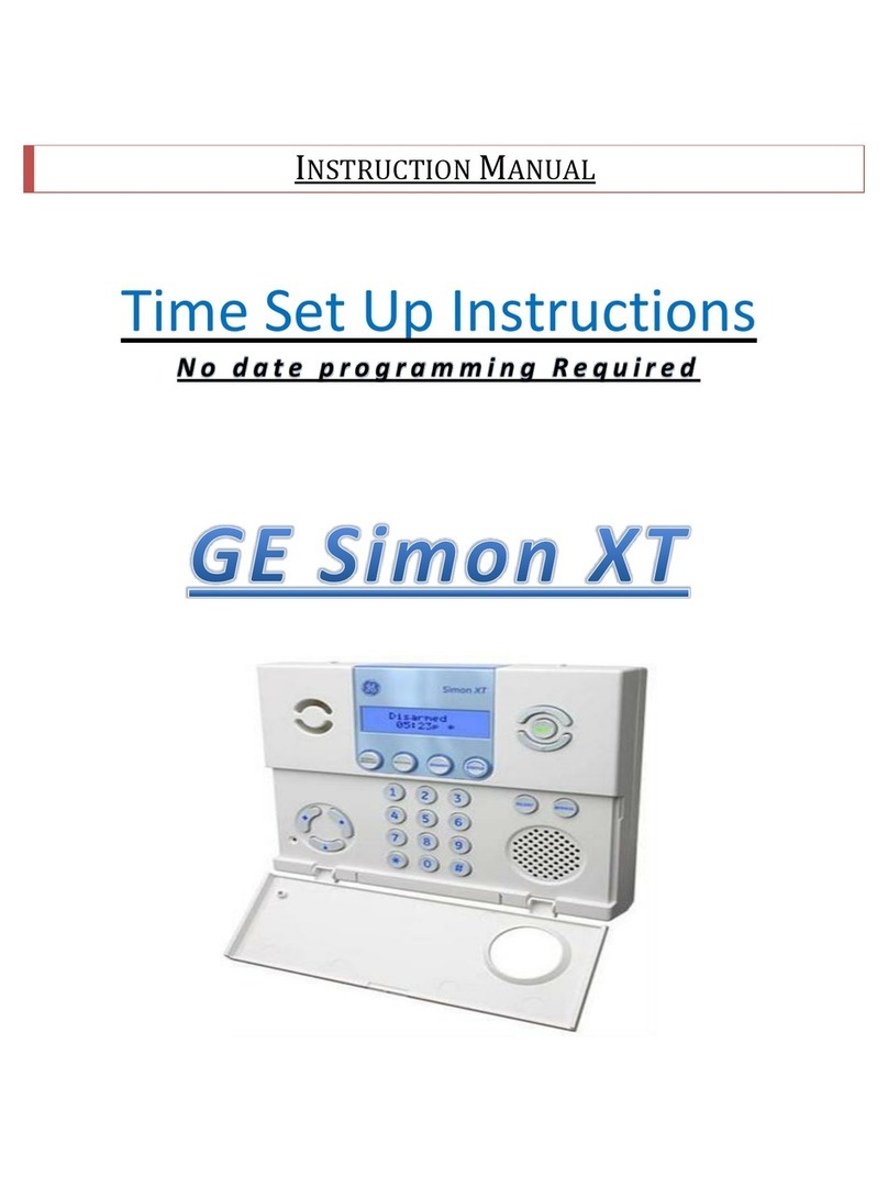
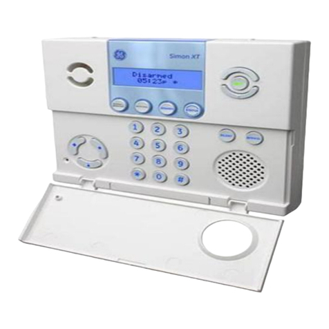
GE SIMON XT User manual

GE

GE SIMON XT User manual

GE 45129 User manual

GE

GE 45129 User manual

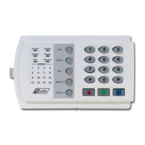
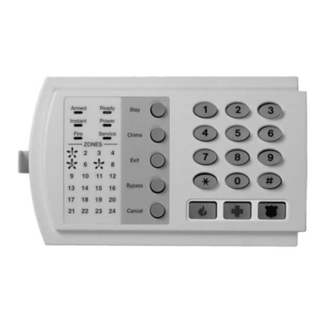
GE NX-1308E - Caddx 8 Zone LED Keypad Installation manual

GE

GE NX-1308E - Caddx 8 Zone LED Keypad Installation manual

GE NetworX NX-6V2 Installation manual

GE

GE NetworX NX-6V2 Installation manual

GE Kilsen KFP-CF2 User manual

GE

GE Kilsen KFP-CF2 User manual

GE NetworX NX-8E User manual

GE

GE NetworX NX-8E User manual

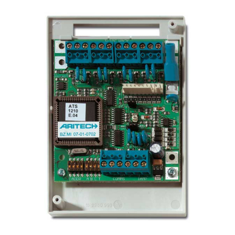
GE Interlogix ARITECH ATS1211 User manual

GE

GE Interlogix ARITECH ATS1211 User manual

GE Kilsen KFP-CF Series User manual

GE

GE Kilsen KFP-CF Series User manual

GE NetworX NX-8-EUR User manual

GE

GE NetworX NX-8-EUR User manual

GE ZITON ZP3 User manual

GE

GE ZITON ZP3 User manual

GE 45633 User manual

GE

GE 45633 User manual

GE NetworX NX-6 Installation manual

GE

GE NetworX NX-6 Installation manual

GE NetworX NX-6V2 User manual

GE

GE NetworX NX-6V2 User manual

GE SIMON XT User manual

GE

GE SIMON XT User manual

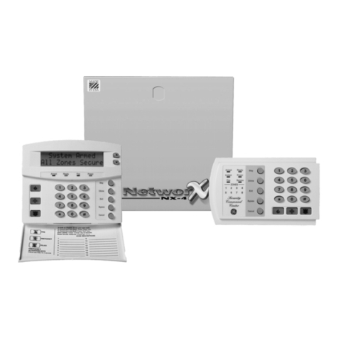
GE NetworX NX-4 Installation manual

GE

GE NetworX NX-4 Installation manual

GE SIMON XT Operating instructions

GE

GE SIMON XT Operating instructions

GE NX-4V2 Installation manual

GE

GE NX-4V2 Installation manual

GE Entelli-Switch 250 User manual

GE

GE Entelli-Switch 250 User manual

GE Alliance AL-2017 User manual

GE

GE Alliance AL-2017 User manual

GE IC754CSF15CTD Installation manual

GE

GE IC754CSF15CTD Installation manual

GE NetworX Series Installation and operation manual

GE

GE NetworX Series Installation and operation manual

GE EST iO64 Product manual

GE

GE EST iO64 Product manual

GE Allegro User manual

GE

GE Allegro User manual

GE Multilin 889 User manual

GE

GE Multilin 889 User manual

Popular Control Panel manuals by other brands

Fondital PROCIDA AWM user manual

Fondital

Fondital PROCIDA AWM user manual

IOT CPT-7 user manual

IOT

IOT CPT-7 user manual

Spirax Sarco Universal Lite Control Panel Installation and maintenance instructions

Spirax Sarco

Spirax Sarco Universal Lite Control Panel Installation and maintenance instructions

Bentel Security Omnia 8/L manual

Bentel Security

Bentel Security Omnia 8/L manual

Mircom FX-3500RCU Application guide

Mircom

Mircom FX-3500RCU Application guide

wallas 3008 manual

wallas

wallas 3008 manual

Inovance MDKE9 Series user guide

Inovance

Inovance MDKE9 Series user guide

Global Fire Equipment JUNO NET Configuration and connections

Global Fire Equipment

Global Fire Equipment JUNO NET Configuration and connections

Mitsubishi Electric E1032 installation manual

Mitsubishi Electric

Mitsubishi Electric E1032 installation manual

Networker TS2500 Operator's manual

Networker

Networker TS2500 Operator's manual

Kramer WSI-1VGA installation instructions

Kramer

Kramer WSI-1VGA installation instructions

U-Prox MP quick start guide

U-Prox

U-Prox MP quick start guide

Menvier Security TSD402 Installation & user guide

Menvier Security

Menvier Security TSD402 Installation & user guide

EuroLite BOARD 8S user manual

EuroLite

EuroLite BOARD 8S user manual

Pego ECP200 STEPPER user manual

Pego

Pego ECP200 STEPPER user manual

Cooper EASICHECK EC2001 Installation and operation manual

Cooper

Cooper EASICHECK EC2001 Installation and operation manual

Blue Giant Blue Genius Touch Control owner's manual

Blue Giant

Blue Giant Blue Genius Touch Control owner's manual

Beckhoff CP69 Series Installation and operating instructions

Beckhoff

Beckhoff CP69 Series Installation and operating instructions

manuals.online logo
manuals.online logoBrands
  • About & Mission
  • Contact us
  • Privacy Policy
  • Terms and Conditions

Copyright 2025 Manuals.Online. All Rights Reserved.