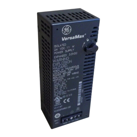
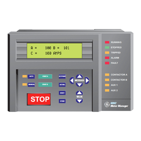
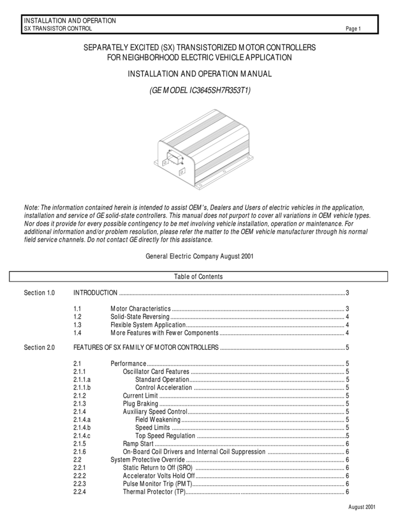
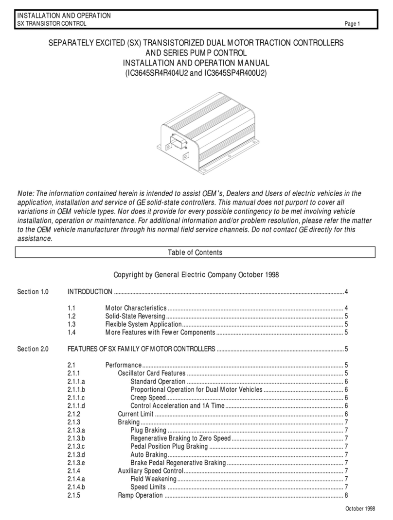
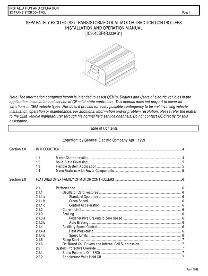
GE EV100 LX User manual

1
INSTRUCTIONS
EV100 LX/LXT SCR
CONTROLS
GEH-5714
The information contained herein is intended to assist truck users and dealers in the servicing of SCR controls furnished
by the General Electric Company. It does not purport to cover all variations in equipment nor to provide for every possible
contingency to be met ith installation, operation or maintenance.
Should further information be desired or should particular problems arise hich are not covered sufficiently for the
purchaser's purpose, the matter should be referred to the truck manufacturer through his normal service channels, not directly
to the General Electric Company.
September 1993
GE Electric Vehicle
Systems

2
EV100LX SCR CONTROL ORDERING INFORMATION
EXAMPLE-------------------------- IC3645EV 100 T1 TT 1
ARGUMENT NO. 01 02 03 04 05
ARGUMENT NO. 01 - BASIC CATALOG NUMBER
ARGUMENT NO. 02 - POWER BASE RATING
100 - EV100 POWER BASE ( APPLICATIONS LESS THAN 150 FLLR
200 - EV200 POWER BASE ( APPLICATIONS LESS THAN 200 FLLR
ARGUMENT NO. 03 - APPLICATION AND 1 REC OPTIONS
T1 - STANDARD CURRENT LIMIT TRACTION
T2 - HIGH PERFORMANCE CURRENT LIMIT TRACTION
P1 - STANDARD CURRENT LIMIT PUMP
P2 - HIGH PERFORMANCE CURRENT LIMIT PUMP
ARGUMENT NO. 04 - LOGIC CARD OPTIONS
MX - TRACTION DUAL MOTOR WITHOUT BDI
MT - TRACTION DUAL MOTOR WITH BDI
PX - PUMP CONTROL WITH TMM
TX - TRACTION WITHOUT BDI
TT - TRACTION WITH BDI
ARGUMENT NO. 0 - REVISION CODE
1 - ACTIVE

3
EV100LX COMPONENT LOCATIONS

4
EV100LX OUTLINE DRAWING

5
EV100LX WITH SPEED LIMIT AND FW
9

6
EV100LX WITH REGEN AND FW
9

7
EV100LX DUAL MOTOR CONTROL
9

8
EV100LX PUMP CONTROL
9

9
NO. PART-NUMBER DESCRIPTION QUANTITY
4 158C3100EEP1 BASE DETAIL ...........................................................01
11 171B3939G1 1REC ASSEMBLY LOW POWER ...........................01
11 171B3939G2 1REC ASSEMBLY HIGH POWER ..........................01
12 273A2523P9 THRM COND INSULATION ...................................01
14 171B3949G1 3 AND 4 REC. ASM. .................................................01
15 259A3290P1 INSULATING BUSHING ..........................................03
16 273A2523P8 THRM COND INSULATION ...................................01
18 44A717068-001 SCR, 2REC .................................................................01
19 44A717067-001 SCR, 5REC .................................................................01
20 44A723544-001 CAP. WARNING LABEL ......................................01
21 44A723543-001 EV-100 LOGO LABEL ..............................................01
22 158C3234G1 REACTOR ASSEMBLY ............................................01
24 259A9053P2 CAP MT FILM 150MF 25 .........................................01
26 IC3645LXCD1TX TRACTION WITHOUT BDI .....................................01
26 IC3645LXCD1TT TRACTION WITH BDI .............................................01
26 IC3645LXCD1MX DUAL MTR TRACTION WITHOUT BDI ...............01
26 IC3645LXCD1MT DUAL MTR TRACTION WITH BDI .......................01
26 IC3645LXCD1PX PUMP CONTROL......................................................01
28 171B3933G1 SPIDER AND WIRE ASM. .......................................01
29 44A727009-G01 THERMISTOR ASM .................................................01
30 171B3940G1 SNUBBER ASM.........................................................04
34 44A718897-001 CAPACITOR MTG. STRAP .....................................02
37 148B5620DPP1 BUS BAR ....................................................................01
38 148B5620DPP2 BUS BAR ....................................................................01
39 148B5620DPP4 BUS BAR ....................................................................01
40 148B5620DPP3 BUS BAR ....................................................................01
43 WH7138R36G1 WIRE HARNESS .......................................................01
48 L201P17B33 NUT, M8X1.25MM ....................................................02
49 L400P10B33 M8 FLAT WASHER ..................................................05
50 L401P27B33 M8 LOCK WASHER .................................................05
52 44A723274-001 M5X50MM T/R SCREW ...........................................04
53 44A723274-002 M5X26MM T/R SCREW ...........................................07
54 L14P17020B33 M8X1.25X20MM SCREW ........................................03
55 L10P14010B33 M5X0.8X10MM SCREW ..........................................05
56 L400P7B33 M5 NAR. FLAT WASHER........................................05
57 L401P25B33 M5 SPRING LOCKWASHER ...................................05
58 44A723274-401 M3.5X12MM T/R SCREW ........................................04
59 L10P11044B33 M3.5X0.6X44MM SCREW .......................................01
60 44A723274-204 M3.5X23MM T/R SCREW ........................................08
61 L400P5B33 M3.5 NAR FLAT WASHER......................................06
62 L401P23B33 M3.5 LOCK WASHER ..............................................06
63 L10P11008B33 M3.5X0.6X8MM SCREW .........................................06
64 L10P11016B33 METRIC PAN HD SCREW.......................................02
67 L14P15016B33 M6X1.0X16MM SCREW ..........................................01
69 L400P8B33 M6 FLAT WASHER ..................................................01
70 171B3954G1 SHUNT-WIRE ASM ..................................................01
73 N402P39B6 WASHER FLAT ST ...................................................03
EV100LX PART NUMBER IDENTIFICATION

10
EV100LX PART NUMBER IDENTIFICATION

11
TERMINAL CONNECTIONS FOR LX/LXT
LOGIC CARDS
TRACTION TRACTION TRACTION TRACTION
INPUT STANDARD SL/FW REGEN/FW DUAL MTR PUMP
TB1 Accel Pot Input Accel Pot Input Accel Pot Input Accel Pot Input Accel Pot Input
TB2 Start Switch Input Start Switch Input Start Switch Input Start Switch Input SL1
TB3 Seat Switch Input Seat Switch Input Seat Switch Input Seat Switch Input SL2
TB4 Key Switch Input Key Switch Input Key Switch Input Key Switch Input Key Switch Input
TB5 Forward Switch Input Forward Switch Input Forward Switch Input Forward Switch Input SL3
TB6 Reverse Switch Input Reverse Switch Input Reverse Switch Input Reverse Switch Input SL4
PA1 Plug Signal Plug Signal Plug Signal PS Coil Driver Status Code 93 Input
PA2 BDI Interrupt BDI Interrupt BDI Interrupt BDI Interrupt Status Code 93 Input
PA3 Aux Hourmeter Input Aux Hourmeter Input Aux Hourmeter Input Aux Hourmeter Input Status Code 90 Input
PA4 Not Used SL2 Sensor 2 Yellow Wire In-Board Mtr Rev Sw Status Code 94 Input
PA5 Not Used SL3 Sensor 2 Green wire Right Mtr Dropout Sw Status Code 94 Input
PA6 Not Used SL1 Mtr A2 Input Left Mtr Dropout Sw Status Code 91 Input
PB1 FW Coil Driver FW Coil Driver FW Coil Driver F Rht Mtr Coil Driver Status Code 95 Input
PB2 Not Used Not Used Regen Coil Driver F Lft Mtr Coil Driver Status Code 95 Input
PB3 SP Coil Driver SP Coil Driver SP Coil Driver R Rht Mtr Coil Driver BDI Enable Signal Input
PB4 F Coil Driver F Coil Driver F Coil Driver R Lft Mtr Coil Driver Pump (PMT Coil Driver
PB5 R Coil Driver R Coil Driver R Coil Driver 1A coil Driver 1A Coil Driver
PB6 1A Coil Driver 1A Coil Driver 1A Coil Driver D Coil Driver Status Code 92 Input
PY1 Dash Display 4 Input Dash Display 4 Input Dash Display 4 Input Dash Display 4 Input Dash Display 4 Input
PY2 Dash Display 3 Input Dash Display 3 Input Dash Display 3 Input Dash Display 3 Input Dash Display 3 Input
PY3 Dash Display 1 Input Dash Display 1 Input Dash Display 1 Input Dash Display 1 Input Dash Display 1 Input
PY4 Dash Display 2 Input Dash Display 2 Input Dash Display 2 Input Dash Display 2 Input Dash Display 2 Input
PY5 Dash Display 5 Input Dash Display 5 Input Dash Display 5 Input Dash Display 5 Input Not Used
PY6 Not Used Not Used Not Used Not Used Not Used
PY7 Im Im Im Not Used Not Used
PY8 TMMA-9 / Pump-PY12 TMMA-9 / Pump-PY12 TMMA-9 / Pump-PY12 TMMA-9 / Pump-PY12 Not Used
PY9 TMMA-7 / Pump-PY11 TMMA-7 / Pump-PY11 TMMA-7 / Pump-PY11 TMMA-7 / Pump-PY11 Not Used
PY10 TMMA-2 / Pump-PY10 TMMA-2 / Pump-PY10 TMMA-2 / Pump-PY10 TMMA-2 / Pump-PY10 Traction PY10
PY11 Not Used Not Used Not Used Not Used Traction PY9
PY12 Not Used Not Used Not Used Not Used Traction PY8
PY13 Not Used Not Used Not Used Not Used Not Used
PY14 Not Used Not Used Not Used Not Used Not Used

12
Control Features
On-Board Diagnostics
Hourmeter
Stored Status Codes
Card Type Selection
Creep Speed
Current Limit
Plugging
Pedal Position Plug
Ramp Start
Full Power Transition
Controlled Acceleration
1A Timed Pick-Up
1A Thermal Hold-Off
1A Plugging Hold-Off
Delay to First Pulse
PMT (Fault Shut Down
Thermal Protection
Static Return to Off
IC364 LXCD1T
Standard Displayed to
Handset or Dash Display
Standard Displayed to
Handset or Dash Display
Standard
Standard Enable/Disable
Features
Adjustable
2% to 15% On Time
Adjustable
See C/L Curves
Standard/High
Performance
Adjustable
200 to 930 Amps
Adjustable
100 to 930 amps
Can be Disabled
Standard
Standard with 1A Ctr
Adjustable
.1 to 22 seconds
Follows CA by .2 seconds
with Accel Volts is < .5V
or Accel Ohms is < 200
Standard at 90oC
cutback at 20% TON
Standard
Standard
Standard
Look Ahead and Reset two
count
Standard
90oC Cutback
Standard
2 Second Delay
IC364 LXCD1M
Standard Displayed to
Handset or Dash Display
Standard Displayed to
Handset or Dash Display
Standard
Standard Enable/Disable
Features
Adjustable
2% to 15% On Time
Adjustable
See C/L Curves
Standard/High
Performance
Adjustable
200 to 930 Amps
Adjustable
100 to 930 amps
Can be Disabled
Standard
Standard with 1A Ctr
Adjustable
.1 to 22 seconds
Follows CA by .2 seconds
with Accel Volts is < .5V
or Accel Ohms is < 200
Standard at 90oC
cutback at 20% TON
Standard
Standard
Standard
Look Ahead and Reset two
count
Standard
90oC Cutback
Standard
2 Second Delay
IC364 LXCD1P
Standard Displayed to
Handset or Dash Display
Standard Displayed to
Handset or Dash Display
Standard
Standard Enable/Disable
Features
Not Applicable
Adjustable
See C/L Curves
Standard/High
Performance
Not Applicable
Not Applicable
Not Applicable
Standard with 1A Ctr
Adjustable
.1 to 5.5 seconds
Follows CA by .2 seconds
with Accel Volts is < .5V
or Accel Ohms is < 200
Standard at 90oC
cutback at 20% TON
Not Applicable
Standard
Standard
Look Ahead and Reset two
count
Standard
90oC Cutback
Not Applicable
EV100LX Logic Card Specifications

13
Control Features
Voltage Range
Accelerator Input
Low Battery Operation
Reverse Battery Protection
Ambient Temperature
Approximate Weight
Coil Drivers
F/R or Line
1A
FW
Regen
D
PS
Shorted Driver Protection
Shorted 3 REC Protection
F/R and Speed Input
Switch Loading
1A switch
1A Current dropout
Dual Mtr Steering Logic
Dual Mtr Inside Wheel
Reversal
Regenerative Braking
Field Weakening
Speed Limit
Three Ranges
Creep to Full Speed
Steer pump Time Delay
IC364 LXCD1T IC364 LXCD1M IC364 LXCD1P
24-80 VDC
5000-0 Ohms
3.5-0 VDC
Standard
50% at 36-80 VDC
75% at 24 VDC
Standard
-30 to +50oC
5.5 Kg
On-Board
On-Board
On-Board
On-Board
Not Applicable
On-Board
Standard
Standard
Logic Current
Not Required
Adjustable
450 to 1260 Amps
Not Available
Not Available
Adjustable
Regen C/L - 75A to 630A
Regen Start - 15% to 96%
Adjustable
Pick-up - 52A - 466A
Drop-out - 65A to 895A
Standard
Adjustable
Input by Limit Switch
Seat - .5 to 63 sec
Neutral - .5 to 63 sec
24-80 VDC
5000-0 Ohms
3.5-0 VDC
Standard
50% at 36-80 VDC
75% at 24 VDC
Standard
-30 to +50oC
5.5 Kg
On-Board
On-Board
Not Applicable
Not Applicable
On-Board
On-Board
Standard
Standard
Logic Current
Not Required
Adjustable
450 to 1260 Amps
Standard
Standard
Not Applicable
Not Applicable
Standard
Adjustable
Two Speed Limits
Seat - .5 to 63 sec
Neutral - .5 to 63 sec
24-80 VDC
5000-0 Ohms
3.5-0 VDC
Standard
50% at 36-80 VDC
75% at 24 VDC
Standard
-30 to +50oC
5.5 Kg
On-Board
On-Board
Not Applicable
Not Applicable
Not Applicable
Not Applicable
Standard
Standard
Logic Current
Not Required
Not Applicable
Not Available
Not Available
Not Applicable
Not Applicable
Standard
Adjustable
Input by Limit Switch
Not Applicable

14
Control Features
Accelerator Volts Lockout
Accel volts > 2.5V
Battery Volts Check
Battery Discharge Indica-
tion
Full Load Level Running
Mtr Current at 50% 1A
duty
Continuous Duty Mtr
Current with 0.3oC/Watt
Heatsink at 40oC Ambient
Plug Current Limit
Min-Max @ 1 Sec
Min-Max @ 3 Sec
Average Motor C/L with
Typical Mtr Inductance
Min-Max @ 30% TON
Min-Max @ 50% TON
Min-Max @ 70% TON
Min-Max @ 30% TON
Min-Max @ 50% TON
Min-Max @ 70% TON
IC364 LXCD1T
Standard
Standard
Optional
150 Amps Plus
103 Amps Plus
330/950 Amps
330/650 Amps
405/640 Amps (STD
320/565 Amps (STD
230/495 Amps (STD
475/690 Amps (H/P
455/685 Amps (H/P
435/680 Amps (H/P
IC364 LXCD1M
Standard
Standard
Optional
150 Amps Plus
103 Amps Plus
330/950 Amps
330/650 Amps
405/640 Amps (STD
320/565 Amps (STD
230/495 Amps (STD
475/690 Amps (H/P
455/685 Amps (H/P
435/680 Amps (H/P
IC364 LXCD1P
Standard
Standard
Optional
150 Amps Plus
103 Amps Plus
Not Applicable
405/640 Amps (STD
320/565 Amps (STD
230/495 Amps (STD
475/690 Amps (H/P
455/685 Amps (H/P
435/680 Amps (H/P
EV100LX Traction and Pump H/P Curve EV100LX Traction and Pump STD Curve

15
BASICS OF CIRCUIT OPERATION
The control circuit is energized by closing the key switch, seat switch, and moving the for-
ward or reverse lever to either position, and then depressing the accelerator closing the start switch.
This applies power to the control card turning on the PMT driver , which will close the selected
directional contactor and complete the circuits to the drive motor. (See elementary drawings.
The control card then supplies a gate pulse to 2REC turning it on to a conducting state,
allowing current to flow from the battery through lC, lX, 2REC, motor field, motor armature, sensor,
and back to the battery. After lC charges, 2REC shuts off due to lack of holding current. The con-
trol card checks that lC is charged and unlocks the gate to lREC and 5REC.
The control card then supplies a gate pulse to lREC turning it on to a conducting state, allow-
ing current to flow from the battery through lREC, motor field, motor armature, sensor, and back to
the battery. 5REC turns on and allows current to flow T4-T3, lC, lREC, 5REC to T4-T3. This
current charges the bottom of lC positive with respect to the battery positive bus. This charging cycle
occurs in less than l millisecond (.00l sec. and 5REC shuts off. This charge is now stored on the
capacitor until it is time to turn off lREC.
Current continues to flow in lREC until the control card fires 2REC. When 2REC conducts,
capacitor lC discharges around the circuit composed of lC, 1X, 2REC, and lREC. This discharge
current opposes the battery current through lREC so that the resultant current is zero. With reverse
voltage across lREC, lREC is turned off. Current continues to flow in the 2REC, lC, motor and
battery loop until the capacitor (card terminal l4 is fully charged negative. This charge exceeds
battery voltage by an amount which is a function of peak motor current, and 2REC turns off. Figure l
illustrates the pulsing of current from the battery.
Figure l Figure 2
During the off time, the energy stored in the motor, by virtue of the motors inductance, will
cause current to circulate through the motor around the loop formed by 3REC. Thus, providing MD=J

16
is called flyback current. Figure 2 shows the nature of the motor current which is composed of
both battery current and the inductive flyback current. It should be noted that the average motor
current measured will be greater than the average battery current. The SCR control, in effect, con-
verts battery current at battery volts into a higher motor current and a lower motor volts.
The time for the next ON and OFF cycle to start is determined by the time that the control
card takes to oscillate. This frequency of oscillation is controlled by the potentiometer in the accel-
erator and automatic circuitry in the card. Slow speed is obtained by having maximum ohms in the
potentiometer. As the resistance in the potentiometer decreases, the speed of the motor increases.
The SCR circuit is capable of delivering approximately 95% speed. For full speed operation, the lA
contactor is closed to apply full battery voltage across the motor.
CONTROL FEATURES
OSCILLATOR - the oscillator section of the card has two adjustable features and one fixed feature.
With the accelerator potentiometer at maximum ohms, the creep speed can be adjusted by the
handset unit. Top speed is fixed by card and is
obtained with the accelerator potentiometer at
minimum ohms. The % ON time has a range of
approximately 5 to 95 percent. The center
operating condition of the oscillator is at 50
percent ON time with a nominal l.8 milliseconds
ON time and l.8 millisecond OFF time. This
corresponds to a maximum operating frequency
of about 300 hertz. At creep the ON time will
decrease to approximately 0.8 milliseconds while
OFF time will become in the order of 20 milli-
seconds. At full SCR operation, this condition
will be reversed (short OFF time, long ON time .
This variation of ON and OFF time of the
oscillator produces the optimum frequencies
through the SCR range. The frequency curve of
the oscillator is shown in Figure 3.
The rate at which the oscillator may increase its percent ON time is limited by Controlled
Acceleration. The minimum time required to go from creep speed to 80-85% on time point may be
varied by the C/A trimpot on the card, adjustable from approximately 0.1 seconds to 22.0 seconds.
CURRENT LIMIT - This circuit monitors motor current by utilizing a sensor in series with the
armature. The information detected across the sensor is fed back to the card so current may be
limited to a pre-set value. If heavy load currents are detected, this circuit overrides the oscillator and
limits the average current to a value set by function 4 of the handset. The C/L setting is based on the
maximum thermal rating of lREC and the peak voltage on the capacitor. Because of the flyback
current through 3REC, the motor current usually runs 2 to 3 times battery current. See current limit
curves for available current and adjustment range.
Figure 3

17
PLUGGING - Slow down is accomplished when reversing by providing a small amount of retarding
torque for deceleration. If the vehicle is moving and the directional lever is moved from one direction
to the other, the motor field is reversed. The plug signal is initiated by the fact that the directional
switch has moved from one direction to the other. The motor armature, driven by the inertia of the
vehicle, acts as generator. This generated current passes through 4REC and the sensor. The oscilla-
tor circuit regulates at a plug current limit level as set by the Handset this controls the pulse rate of
lREC to regulate the generated motor current and bring the truck to a smooth stop and reversal. With
the accelerator potentiometer at minimum resistance, function 5 will enable adjustment of plugging
current from max to min. current level for plug current limit.
PEDAL POSITION PLUG - This feature will allow for plugging distance based on pedal position.
Pedal position will reduce the plugging current to the current value set by this function as the accel-
erator is returned to the creep speed position. Maximum plug current is obtained with the accelerator
in the top speed position. This feature is adjustable by using function 16 on the handset.
RAMP START - This feature provides full SCR torque to restart a vehicle on an incline. The
memory for this function is the directional switch. When stopping on an incline, the directional
switch must be left in its original or neutral position to allow the control to assure full power when
restarted. The accelerator potentiometer input will modulate ramp start current.
FULL POWER TRANSITION - this built-in feature provides smooth transition from SCR to lA
bypass. This is accomplished by the SCR continuing to pulse until the lA contactor power tips close.
CONTROL ACCELERATION AND 1A TIME - This feature allows for adjustment of the rate of
time it takes for the control to accelerate to 96% applied battery voltage to the motor on hard accel-
eration. The 1A contactor will automatically close .2 seconds after the controlled acceleration stops
and the accelerator input is less than .5 volts or less than 50 ohms. C/A is adjusted by function 3 from
.1 to 22 seconds.
1A CURRENT DROP OUT - This adjustable feature can be set to open the 1A contactor if the
traction motor is subject to excessive currents. The dropout is adjustable with function 6 of the
handset. Once the control has dropped out the 1A contactor due to excess current, the directional or
accelerator switch must be returned to neutral to unlock the dropout circuit to allow the control to
pick up the 1A contactor again. Using this feature will reduce the 1A contactor tip life, thus it should
be used only where needed to protect the motor.
STATIC RETURN TO OFF - This built-in feature of the control is set up to make the driver return
the directional lever to neutral anytime he leaves the vehicle and returns. If the seat switch or key
switch is opened, the control will shut off and cannot be restarted until directional lever is returned to
neutral. A time delay of approximately .75 seconds is built into the seat switch input to allow mo-
mentary opening of the seat switch if a bump is encountered.
ACCELERATOR VOLTS HOLD-OFF This feature checks the voltage level at the accelerator
input when ever the key switch or seat switch is activated. If the voltage is less than 2.5 volts the
control will not start. This is to assure that the control is calling for low speed operation at start-up.

18
COIL DRIVER MODULES - these drivers are internal to the control card. They are the power
devices that operate F, R, lA, D, FW, RB, and PS contactor coils. These drivers open or close these
coils on command from the control card. All modules are equipped with reverse battery protection in
that if the battery is connected incorrectly, none of the contactors controlled can be closed electri-
cally.
lA THERMAL HOLD OFF - this feature prevents the lA contactor from closing when the truck is
in severe thermal cutback to avoid torque jumps. When the control goes into severe cutback, the
must pulse to time will inhibit the lA timer.
MUST PULSE TO TIME - this feature prevents the lA timer from timing if the oscillation pulse rate
has not reached a particular level of operation.
PULSE MONITOR TRIP ( PMT ) - This feature contains three features which shuts down or locks
out control operation if fault conditions exist that would allow uncontrolled ( run away speed of the
vehicle:
Look ahead
Look again
Automatic look again and reset
The PMT circuit will not allow the control to start under the following conditions:
1. If 1REC is shorted or if 1A contactor is welded, the control will not allow the F or R
contactor to close.
2. Will not allow the control to operate if F and R internal coil drivers are shorted or if
3REC diode is shorted.
The PMT circuit will shut down operation of the control ( opening of the F or R contactor under the
following conditions:
If 1REC fails to commutate ( shut off , or if 1A power tips remain closed when they should be open.
After opening the F or R contactor the PMT circuit will check for a fault and if none is found will
reclose the directional contactor. If the fault still exist, the directional contactor will open and remain
open.
If 1A closes before a second commutation failure, the look again counter will automatically reset.
This eliminates the inconvenience of resetting the PMT with the key switch if the trip is due to ran-
dom noise.
When the PMT circuit prevents F or R contactors from closing, the PMT circuit can be reset only by
opening the key switch.
THERMAL PROTECTOR - (TP - this temperature sensitive device is mounted on the lREC heat
sink. If the lREC temperature begins to exceed the design limits, the thermal protector will lower the

19
maximum current limit and not allow lREC to exceed its temperature limits. Even at a reduced
current limit, the vehicle will normally be able to reach sufficient speed for full lA operation, thereby
allowing the panel to cool. As the panel cools, the thermal protector will automatically return the
control to full power.
LOW VOLTAGE- batteries under load, particularly if undersized or more than 80 percent dis-
charged, will produce low voltages at the SCR control terminals. The EV-l00 control is designed for
use down to 50 percent of a nominal battery volts of 36-84 V, and 75 percent of a nominal battery
volts of 24 V. Lower battery volts may cause the control to not operate correctly; however the PMT
should open the F or R contactor in the event of a commutation failure.
FIELD WEAKENING - if the vehicle is supplied with a field weakening circuit, the FW PU and
FW DO (function 7 and 8 can be adjusted from the handset unit. Field weakening is a method of
attaining higher running speed for the vehicle in level operation. The normal settings for this feature
are: pickup of FW contactor from l25 to l50 percent of normal full-load running current (lA , and
dropout of FW contactor from 275 to 300 percent current. The dropout puts the motor back to the
lA range to climb ramps and inclines.
REGENERATIVE BRAKING if the vehicle is moving and the directional lever is moved from one
direction to the other, this initiates a plugging signal by reversing the motor field. During the stan-
dard motoring mode and the plugging mode, the RB contactor remains picked up. In the plugging
mode, the motor armature acts as generator. Once the generated current reaches a particular current
level, the plugging mode transitions to regenerative braking mode.
Transitioning to regenerative braking mode, opens the RB contactor, disconnecting the motor arma-
ture from battery negative and inserting 7REC and REGEN SENSOR-2 in the regen circuit. During
the lREC on time, the field and armature current is increased. During the 1REC off time, the energy
stored in the field and armature generates the regenerative current, which passes through 7REC, #2
sensor, battery, 3REC/4REC and back to motor field and armature.
The control will remain in regenerative mode as long as the regen current can maintain regenerative
current limit. When the regenerative current cannot be maintained and drops below the level set by
the regenerative current limit trimpot (RB C/L , the regenerative braking mode transitions back to
plugging mode. During the transition back to plugging mode, the RB contactor will reclose enabling
the control to function in plugging mode, regulating plugging currents to bring the vehicle to a
smooth stop and reversal. The accelerator potentiometer input will modulate plugging as well as
regenerative braking current. The major advantage of regen is longer motor life due to reduced motor
heating. This feature has two adjustable functions, regen current limit (function 9 and regen start
(function 10 .
DUAL MOTOR OPERATION - This function is used to connect the motor armatures of a dual
motor vehicle system in parallel during a plug if both motors are in operation at the time of the
plug cycle. This prevents the fields from building flux in the opposite directions and prohibits the
motors from acting as a series generator thereby causing uncontrollable plugging torques. This circuit
require the addition of an armature shorting contactor ( D contactor and an additional 4REC diode (
4REC-B . The D contactor only closes when both motors are energized during a plugging cycle.

20
DUAL MOTOR IN-BOARD WHEEL REVERSAL - This feature allows for the control of the in-
board traction motor while in a sharper turning condition. The in-board motor is controlled by inputs
from limit switches located on the rear steering wheel which connect card input points to negative.
Logic for turn switch operation is shown below:
LEFT TURN - L1 and L2 open - motor energized.
- L1 closed and L2 open - motor disabled.
- L1 and L2 closed - motor reversed from normal direction.
RIGHT TURN - R1 and R2 open - motor energized.
- R1 closed and R2 open - motor disabled.
- R1 and R2 closed - motor reversed from normal direction.
DUAL MOTOR SHARP TURN SPEED LIMIT - This handset adjustable feature allows for the
limiting of top speed when either the R1 and R2 or the L1 and L2 switches are both closed.
TOP SPEED ( MOTOR VOLTS ) LIMIT - This feature provides a means to limit motor volts to
three adjustable limits by limit switch opening between input points on the control card and negative.
The lower motor volt limit always takes priority when more than one switch input is closed. This
motor volt limit effects top speed of the SCR, but actual truck speed will vary at any set point de-
pending on the loading of the vehicle. Each speed limit is adjustable by the handset, function 11, 12,
and 13, for speed limits 1, 2, and 3.
STEER PUMP CONTACTOR TIME DELAY - This feature provides two options for SP time
delay option 1 provides a .5 to 63 second time delayed drop out of the steer pump contactor when the
Forward or Reverse directional switch is opened. This is overridden by a 1.5 second time delayed
drop-out whenever the seat switch is opened. Option 2 provides a .5 to 63 second time delayed drop
out of the SP contactor when the seat switch is opened.
CONSTANT CURRENT COIL DRIVERS AND INTERNAL COIL SUPPRESSION - This
feature allows the use of 24 volt contactor coils on through the entire voltage range of the EV100 (
24 volts to 84 volts for the F,R,1A,SP,RG,D,and FW contactors.
This feature also allows the above contactors to operate cooler due to less current being applied to
the coil after pick-up.
HOUR METER READINGS - This feature will display the recorded hours of use of the traction
control and pump control to the dash display each time the key switch is turned off.
INTERNAL RESISTANCE COMPENSATION - This feature is used when the Battery Discharge
Indicator is present. Adjustment of this function will improve the accuracy of the BDI.
TRUCK MANAGEMENT MODULE (TMM1) - is a multi-function accessory card that provides
the OEM the ability to provide status codes or operator warning codes that will be displayed on the
dash display whenever a normally open switch or sensor wire provides a negative signal to the card.
Typically the TMM1A can be used to display over temperature of motors, hydraulic systems or any
other switch that closes at the desired temperature. The TMM1A can also be used to monitor and
display motor brush wear warnings when the motor brushes require replacement.
Other manuals for EV100 LX
1
This manual suits for next models
1
Table of contents
Other GE Controllers manuals
Popular Controllers manuals by other brands

Honeywell
Honeywell MN7220 Product data

Tyco
Tyco iSTAR eX Installation and configuration guide

Centrosolar
Centrosolar Solar SR60UL user manual

Hitachi
Hitachi PC-ARFG2-M Installation & maintenance manual

KMC Controls
KMC Controls BAC-7401 Installation and operation guide

National Instruments
National Instruments NI RMC-8355 installation guide