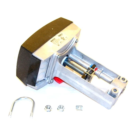
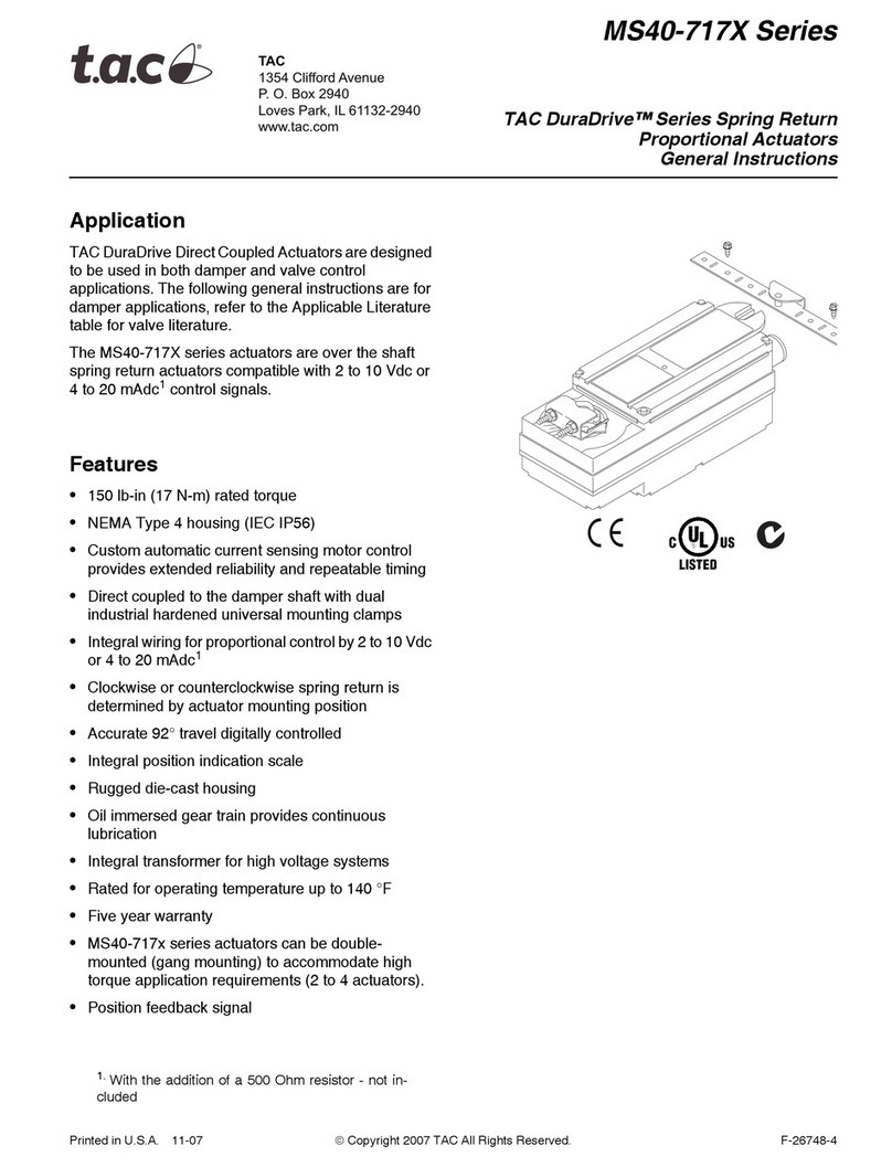
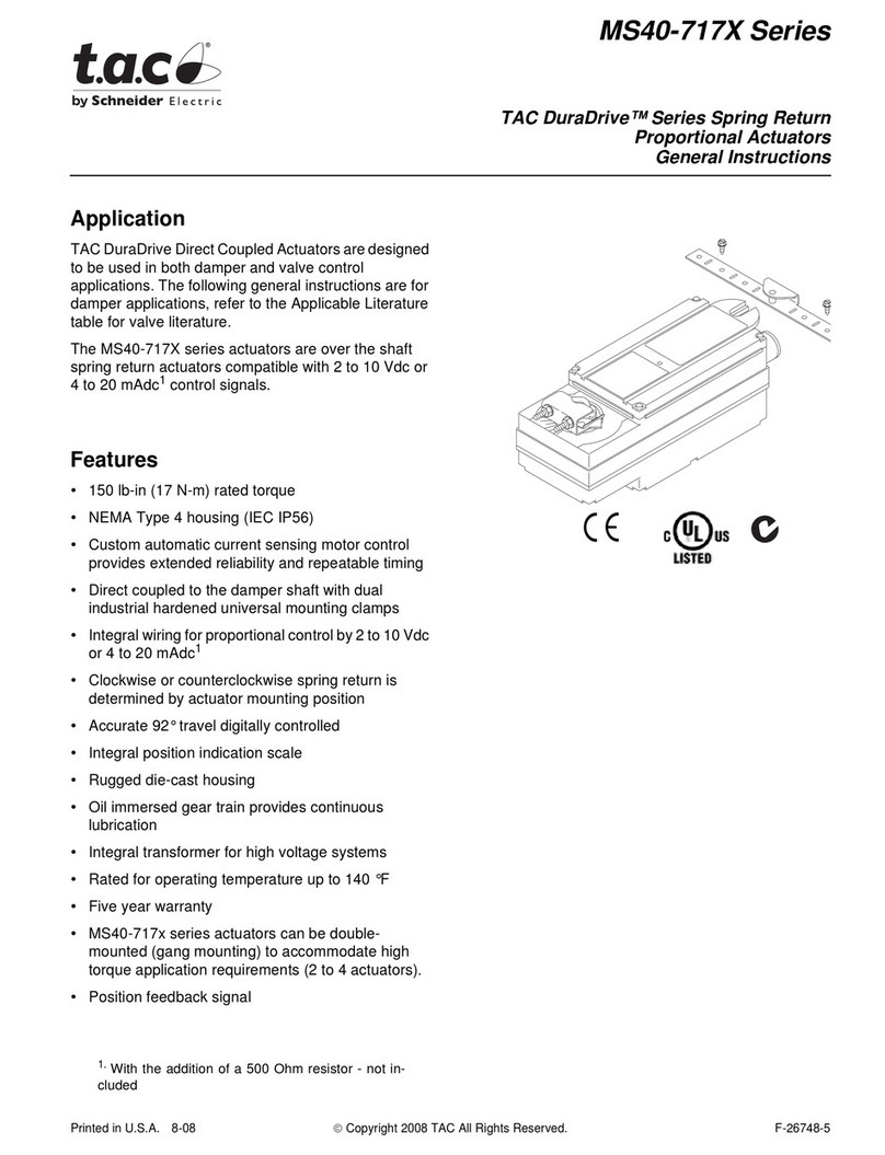
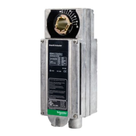
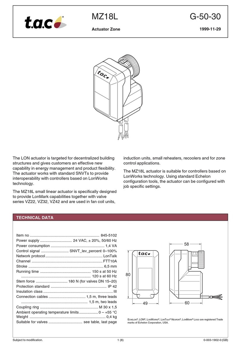
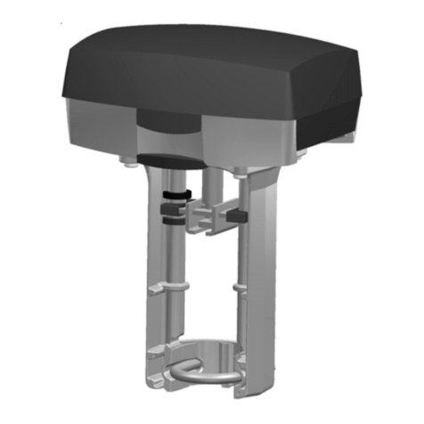
t.a.c. MS-83010 Series Instruction manual

Printed in U.S.A. 1/07 © Copyright 2006 TAC All Rights Reserved. F-19449-5
TAC
1354 Clifford Avenue
P. O. Box 2940
Loves Park, IL 61132-2940
www.tac.com
APPLICATION
For electronic positive positioning proportional control of
dampers, valves or butterfly valves which require the return
to normal position on power interruption. MS-830X0
compatible with 2 to 15 Vdc (TAC System 8000).
SPECIFICATIONS
Controller Signal: 2 to 15 Vdc from TAC System 8000
controller.
Stroke: Over a nominal 6 Vdc (fully retracted) to 9 Vdc (fully
extended) input range. See Tables 1 and 2.
Start Point: Factory set at 6 Vdc, adjustable 2 to 12 Vdc.
Input Impedance: 10,000 ohms or greater.
Spring Return: Damper linkage provides return to normal
position on power interruption.
Power Requirements: See Tables 1 and 2.
Power Supplies: 20 Vdc, 75 mA; 50mA available when
optional auxiliary switch (AM-158) is installed.
Environment:
Ambient Temperature Limits,
Operating Shipping and Storage -40 to 140°F (-40
to 60°C).
Humidity, 5 to 95% RH, non-condensing.
Locations, NEMA Type 1 indoor only.
Connections: Color coded 6" (152 mm) leads.
Case: Die cast aluminum.
Mounting: Any position for damper actuators. In any upright
position with actuator above the center of the valve body.
Dimensions:
MS-8301X, 10-1/2" high x 7-7/8" wide x 7" deep (267 mm
x 200 mm x 178 mm).
MS-8304X, 10-1/8" high x 5-15/16" wide x 15-1/2" deep
(257 mm x 151 mm x 394 mm).
MS-8305X, 8-3/8" high x 5-15/16" wide x 21-3/4" deep
(213 mm x 151 mm x 552 mm).
ACCESSORIES
AM-158 Auxiliary switch kit; 175 VA @ 120/280Vac,
35 VA @ 24 Vac
TOOL-201 Calibration kit for TAC System 8000
Damper Linkage Accessories
AM-111 Crank arm for 5/16" diameter damper shaft
AM-112 Crank arm for 3/8" diameter damper shaft
AM-113 Crank arm for 1/2" diameter damper shaft
AM-115 Crank arm for 7/16" diameter damper shaft
AM-122 Linkage connector straight type
AM-123 Damper clip
AM-125 5/16" diameter x 20" damper rod
AM-125-048 5/16" diameter x 48" damper rod
AM-132 Ball joint connector
AM-161-3 Damper linkage kit
For MS-8301X Series Only
AV-430 Valve linkage
AV-495 Valve linkage
For MS-8305X Series Only
AM-301 90 degree mounting bracket for pivot
mounting
AM-530 Crank arm for 1/2" dia. damper shaft holes
for 3-1/2" stroke
AM-532 Bolt-on frame lug and damper blade clip kit
AM-533 Actuator shaft extension
AM-534 Pivot stud for pivot mounting
AM-535 Clevis for pivot mounting
AM-536 Mounting plates for pivot mounting on ducts
or damper frame
MS-83010, MS-83040 &
MS-83050 Series
Actuators
General Instructions
Table-1 Valve Actuator Selection Specifications.
Part Number
Supply Voltage
50/60 Hz (Vac) 10
Watts
VA
Rating
Output
Description Force Valve
Timing at 70°F (21°C)
No Load Strokea
a220 Vac at 50 Hz (+1-%, - 15%) the power stroke is approximately 25% slower and the VA is 20% more.
Retract
MS-83010 120 (+10%, -15%) 47
Proportional 1"
(25 mm) stroke 150 pounds
VB-9XXX 1-1/2
thru 4"
See Table 3.
2-1/4 min.
+25 sec. 1/2 min. +10 sec.MS-83011 240 (+10%, -15%) 46
MS-83013 24 (+10%) 44

2© Copyright 2006 TAC All Rights Reserved. F-19449-5
PRE-INSTALLATION
Inspection
Inspect the package for damage. If damaged, notify the
appropriate carrier immediately. If undamaged, open the
package and inspect the device for obvious damage due to
shipping. Return damaged products.
Required Installation Items
•Wiring diagrams
•Tools (not provided):
Digital volt-ohm meter (DVM)
Appropriate drill and drill bit for mounting screws
Appropriate wrenches for adjustment of damper and
valve linkages
TOOL-209, 135 ohm slidewire and 0 to 7 mA manual
positioner
•Appropriate accessories
•Mounting screws or bolts (not provided)
•Wire nuts (not provided)
INSTALLATION
Caution:
1. Installer must be a qualified, experienced technician.
2. Disconnect power supply before installation to prevent
electrical shock and equipment damage.
3. Make all connections in accordance with electrical wiring
diagram, and in compliance with national and local codes.
Use copper conductors only.
4. Do not exceed the ratings of the device.
5. Avoid locations where excessive moisture, corrosive
fumes or vibration are present. NEMA Type 1 housings
are intended for indoor use primarily to provide a degree
of production against contact with enclosed equipment.
Mounting
The actuator can be mounted in any position in a weather
protected area. It is recommended that valve actuators be
mounted above the centerline of the valve body. When
selecting a location, allow sufficient room for accessories and
for service of the product.
MS-8301X Valve Actuators
For the correct installation of valve linkages refer to the
instruction sheets for AV-430 (F-19072) or AV-495 (F-21665)
which-ever is appropriate for the particular valve body.
Figure-1 Dimensions for MX-830XX Series.
MS-8304X 75 lb.-in. Damper Actuator
Typical Mounting
Accessories typically required for mounting per Figure 3
•Crank arm for damper shaft; AM-111, AM-112, AM-113 or
AM-115
•Ball joint; AM-122 or AM-132
•Damper rod, 5/16" dia.; AM-125 or AM-125-048
Table-2 Damper Actuator Selection Specifications (linkage provided)
Part Number
Supply Voltage
50/60 Hz (Vac)
10 Watts
VA Rating Output
Description
Application Timing at 70°F (21°C)
Proportional
Torque
Rating lb.-in.
(N-m) for
Determining
Damper Area
Proportional Control
Nominal Damper Areaa
sq. ft. (m2)NoLoad
StrokebRetract
Parallel Opposed
MS-83040 120 (+10%, -15%) 47 Proportional
2" (51 mm)
stroke
75 (8.5) 42 (3.9) 54 (5) 2-1/4 min.
+25 sec.
1/2 min.
+10 sec.
MS-83041 240 (+10%, -15%) 46
MS-83043 24 (+10%) 44
MS-83050 120 (+10%, -15%) 47 Prop. 3-1/2"
(89 mm)
stroke
190 (21.5) 106 (9.8) 137 (12.7) 4 min.
+40 sec.
1-1/2 min.
+15 sec.
MS-83051 240 (+10%, -15%) 46
MS-83053 24 (+10%) 44
aDamper ratings are nominal and based on standard (not low leakage) dampers at 1" (25.4 mm) W.C. pressure and 2000 fpm (10 m/s) velocity.
b220 Vac at 50 Hz (+1-%, - 15%) the power stroke is approximately 25% slower and the VA is 20% more.
Table-3 MS-8301X Valve Body and Linkage (order
separately).
Linkage End Fitting Size
(in.) Valve Body
AV-430 1-1/2 thru 2 VB-92X3, VB-92X4, VB-9313,
VB-9314, VB-9323
2-1/2 thru 3 VB-9323
AV-495 2-1/2 thru 4 VB-92X3, VB-9313

F-19449-5 © Copyright 2006 TAC All Rights Reserved. 3
Mounting Tips
1. Select a convenient position to mount the damper actuator
that will provide the desired normal position of the damper,
see Figure 3.
2. The damper should be linked for angular rotation of less
than 90° that will provide the required flow. This will
provide the optimum close-off and controllability.
Typically 60° rotation of the damper will provide almost
maximum flow.
3. Damper rod that is too long is not rigid enough for good
control and damper rod that is too short makes it difficult
to adjust the linkage.
4. The best position for the actuator is with the actuator
crank arm and the damper crank arm at 90° angle to the
damper push rod when actuator is in mid-stroke, see
Figure 3.
Figure-2 Dimensions for MS-8304X Series.
Mounting Instructions (Refer to Figure 3)
1. Hold the actuator up to the duct in an appropriate position
and mark the four (4) mounting hole positions.
2. With an appropriate drill or punch, pierce the mounting
holes marked in step1.
3. Using four (4) screws or bolts (not provided) mount the
actuator to the duct.
4. Attach a ball joint to the slot in the damper crank arm at a
position from the centerline of the shaft hole in the crank
arm; position equal approximately 1-1/2" (38.1 mm) for
90° damper rotation and 2" (50.8 mm) for 60° damper
rotation.
5. Rotate the damper to its normal position. Attach and
secure the damper crank arm to the damper shaft at an
angle (30° for 60° rotation damper and 45° for 90° rotation
damper) from the mid-stroke position of the crank arm
and pointing toward the actuator.
6. Slide the damper rod through the ball joint on the damper
crank arm and into the connector on the actuator. Tighten
the nut on the connector on the actuator. Cut off
excessive damper rod.
Figure-3 Typical Mounting for MS-8304X Series.
For normally open dampers
, tighten the nut on the ball
joint. When the damper is closed the actuator should be
1/16" (1.6 mm) from the extend end of stroke (verify in
step 8).
For normally closed dampers
, push the damper closed
using the crank arm and tighten the nut on the ball joint
while holding the damper closed. This adjustment should

4© Copyright 2006 TAC All Rights Reserved. F-19449-5
be made when the actuator is powered and positioned
so that it is 1/16" (1.6 mm) off its retract positioned so
that it is 1/16" (1.6 mm) off its retract position to ensure
close-off of the damper.
7. After the actuator is powered and can be controlled, refer
to the CHECKOUT section to ensure the damper is linked
correctly.
MS-8305X 190 lb.-in. Damper Actuator Typical
Damper Duct Mounting
Accessories typically required for mounting per Figure 5
•Crank arm for damper shaft; AM-111, AM-112, AM-113 or
AM-115
•Ball joint; AM-122 or AM-132
•Damper rod, 5/16" dia.; AM-125 or AM-125-048
Figure-4 Dimensions for MS-8305X Series.
Mounting Tips
1. Select a convenient position to mount the damper actuator
that will provide the desired normal position of the damper,
see Figure 5.
2. The damper should be linked for angular rotation of less
than 90° that will provide the required flow. This will
provide the optimum close-off and controllability.
Typically 60° rotation of the damper will provide almost
maximum flow.
3. A damper rod that is too long is not rigid enough for good
control and a damper rod that is too short makes it difficult
to adjust the linkage.
4. The best position for the actuator is with the damper
crank arm at a 90° angle to the damper push rod when
actuator is in mid-stroke, see Figure 5.
Figure-5 Typical Duct Mounting for MS-8305X Series.

F-19449-5 © Copyright 2006 TAC All Rights Reserved. 5
Mounting Instructions (Refer to Figure 5)
1. Hold the actuator up to the duct in an appropriate position
and mark the four (4) mounting hole positions.
2. With an appropriate drill or punch, pierce the mounting
holes marked in step 1.
3. Using four(4) screws or bolts (not provided) mount the
actuator to the duct.
4. Attach a ball joint to the slot in the damper crank arm at a
position from the centerline of the shaft hole in the crank
arm; position equal approximately 2-1/2" (88.9 mm) for
60° damper rotation.
5. Rotate the damper to its normal position. Attach and
secure the damper crank arm to the damper shaft at an
angle (30° for 60° rotation damper and 45° for 90° rotation
damper) from the mid-stroke position of the crank arm
and pointing toward the actuator.
6. Slide the damper rod through the ball joint on the damper
crank arm and into the connector on the actuator. Tighten
the nut on the connector on the actuator. Cut off
excessive damper rod.
7. For normally open dampers, tighten the nut on the ball
joint. When the damper is closed the actuator should be
1/16" (1.6 mm) from the extend end of stroke (verify in
step 8).
For normally closed dampers, push the damper closed
using the crank arm and tighten the nut on the ball joint
while holding the damper closed. This adjustment should
be made when the actuator is powered and positioned so
that it is 1/16" (1.6 mm) off its retract position to ensure
close-off of the damper.
8. After the actuator is powered and can be controlled, refer
to the CHECKOUT section to ensure the damper is linked
correctly.
MS-8305X 190 lb.-in. Damper Actuator Typical
Internal Pivot Mounting (Damper Leaf Connector)
Accessories typically required for mounting per Figures
6 through 9 and 12 through 14
•Frame bracket kit; AM-532 bolt-on
•Actuator shaft extension; AM-533
•Pivot stud for pivot mounting; AM-534
•Clevis for pivot mounting; AM-535
•Mounting plate for pivot mounting; AM-536
•Brace kit for pivot mounting (optional); AM-538
Mounting Instructions (Refer to Figures 6 through 9)
1. Prepare the damper by drilling the necessary holes, etc.
See Figures 8, 9 and 14 for bolt-on bracket.
2. Attach frame bracket and leaf connector to the damper.
3. Attach actuator mounting plate to the frame bracket (see
Figure 6, 7 and 12).
4. Install pivot stud into the correct hole in the actuator
mounting plate (see Figures 6, 7 and 12).
5. Remove the ball joint connector from the actuator.
6. Install the shaft extension onto the actuator shaft.
7. Install the clevis onto the shaft extension.
8. Install the actuator to the pivot stud.
9. Rotate the damper to its normal position.
10. For a normally open damper, adjust the clevis until the
hole in the clevis aligns with the hole in the leaf connector
and then install clevis pin and cotter pin. When the
damper is closed the actuator should be 1/16" (1.6 mm)
from the extend end of stroke (verify in step 11).
For a normally closed damper, adjust the clevis until the
hole in the clevis aligns with the hole in the leaf connector
when the damper is pushed closed and then install clevis
pin and cotter pin. This adjustment should be made when
the actuator is powered and positioned so that it is 1/16"
(1.6 mm) off its retract position to ensure close-off of the
damper.
11. After the actuator is powered and can be controlled, refer
to the CHECKOUT section to ensure the damper is linked
correctly.
Figure-6 Typical Internal Pivot Mounting for MS-8305X
Series (Damper Leaf Connector), Normally Open.
Figure-7 Typical Internal Pivot Mounting for MS-8305X
Series (Damper Leaf Connector) Normally Closed.

6© Copyright 2006 TAC All Rights Reserved. F-19449-5
Figure-8 Typical Bolt-on Bracket Mounting (AM-532).
Figure-9 Installation of Damper Leaf Connector.
Figure-10 Typical External Pivot Mounting for MS-8305X
Series (Crank Arm), Normally Closed.
MS-8305X 190 lb.-in. Damper Actuator Typical
External Pivot Mounting (Crank Arm)
Accessories typically required for mounting per Figures
10 through 13 and 15
•Crank arm; AM-530
•Actuator shaft extension; AM-533
•Pivot stud for pivot mounting; AM-534
•Clevis for pivot mounting; AM-535
•Mounting plate for pivot mounting; AM-536
•Brace kit for pivot mounting (optional); AM-538
Mounting Instructions
Refer to Figures 10 through 13 and 15.
1. Attach the mounting plate to the duct or wall with the
damper shaft protruding through the locator hole in the
mounting plate. If this is not possible, additional shaft
extensions may be used to allow locating the actuator
farther from the damper shaft. Each extension provides 4"
(101.6 mm) of extension to the actuator shaft.
2. Install pivot stud into the correct hole in the actuator
mounting plate (see Figures 10 through 12).
3. Remove the ball joint connector from the actuator.
4. Install the shaft extension onto the actuator shaft.
5. Install the clevis onto the shaft extension.
6. Install the actuator to the pivot stud.
7. Rotate the damper to its normal position.
8.
For a normally open damper
, adjust the clevis until the
hole in the clevis aligns with the correct hole in the crank
arm and then install clevis pin and cotter pin. When the
damper is closed the actuator should be 1/16" (1.6 mm)
from the extend end of stroke (verify in step 9).
For a normally closed damper
, adjust the clevis until the
hole in the clevis aligns with the correct hole in the crank
arm when the damper is pushed closed and then install
clevis pin and cotter pin. This adjustment should be made
when the actuator is powered and positioned so that it is
1/16" (1.6 mm) off its retract position to ensure close-off
of the damper.
9. After the actuator is powered and can be controlled, refer
to the CHECKOUT section to ensure the damper is linked
correctly.
Figure-11 Typical External Pivot Mounting for MS-8305X
Series (Crank Arm), Normally Open.

F-19449-5 © Copyright 2006 TAC All Rights Reserved. 7
Figure-12 AM-536 Mounting Plate.
Figure-13 AM-535 Clevis.
Figure-14 AM-532 Bolt-on Frame Bracket.
Figure-15 AM-530 Crank Arm.
AM-538 Brace Kit for Pivot Mounted MS-8305X
Actuators
The AM-538 brace kit is used with pivot mounted MS-8305X
actuators when additional support is needed to stiffen the
mounting bracket.
Figure-16 Installation of AM-538 Brace Kit.
Mounting Instructions (Refer to Figure 16)
1. Thread 5/16" - 24 hex nut and then the rod end fitting onto
the thread rod and secure rod end fitting by jamming lock
nut against the rod end fitting.
2. Insert the 3/8" hex head bolt through the rod end fitting
and then through the top hole in the leaf connector. Use
lock washer and 3/8" - 16 hex nut to loosely secure.
3. Thread a 5/16" - 24 hex nut about 7" (180 mm) down the
threaded rod.
4. Loosen the nuts on the pivot stud of the actuator.
5. Slide the threaded rod from the damper side through the
hole in the end of the pivot stud.
6. Locate the leaf connector on the edge of the damper
frame and mark the positions to drill mounting holes.
7. Drill the two (2) mount holes 7/32" (6 mm) in diameter.

8© Copyright 2006 TAC All Rights Reserved. F-19449-5
8. Mount the leaf connector to the damper frame with #10
self-tapping screws that are provided.
9. Thread a 5/16" - 24 hex nut onto the threaded rod and
tighten the two nuts on the threaded rod against the pivot
stud.
10. Tighten the pivot stud nuts to the actuator mounting
bracket and tighten the rod end bolt.
WIRING
The wiring connections are made to 6" (152 mm) color coded
leads. See Figure 17 and Tables 4 through 6 for wiring
information.
Note:
All wiring must be Class 1 circuits
Control Leads
Use 18 gage three-conductor twisted leads (Part Number
W-103) for runs up to 500 ft (157 m) between the controller
and the actuator. Use a larger size for longer runs.
Caution:
Use 18 gage shielded cable (twisted) when it is
necessary to install the signal leads in the same conduit with
power wiring, or when high RFI/EMI generating devices are
near. Terminate the shield at the controller only on the COM
(-) terminal. Never connect the shieldings to earth ground.
Power Leads
See Table 4 for selection of proper gage wire versus voltage
and length of wire run.
Figure-17 Typical Wiring MX-83000 Series.
Table-4 Power Wire Selection
Actuator Part
Number Voltage Wire Size
(AWG)
Maximum Run ft.
(m) (1 run has 2
wires)
MS-83013
MS-83043
MS-83053
24 Vac
14 125 (38)
12 196 (59)
10 310 (94)
MS-83010
MS-83040
MS-83050
120 Vac 14 2600 (792)
MS-83011
MS-83041
MS-83051
240 Vac 14 2600 (792)
Table-5 Valve Position Versus Input Signal (Figure 17).
Valve Body
Series
Normal
Position
MS-83010 (120 Vac)
MS-83011 (240 Vac)
MA-83013 (24 Vac)
Increasing Vdc
Input Signal
Normal
Position
Decreasing Vdc
VB-9213-0-4-P
VB-9213-0-5-P
VB-9214-0-4-P
VB-9253-0-4-P
VB-9273-0-4-P
Open Closes Valve Opens Valve
VB-9223-0-4-P
VB-9223-0-5-P
VB-9224-0-4-P
VB-9224-0-4-P
VB-9263-0-4-P
VB-9283-0-4-P
Closed Opens Valve Closes Valve
VB-9313-0-4-P
VB-9313-0-5-P
VB-9314-0-4-P
Flow
B to AB Flow A to AB Flow B to AB
VB-9323-0-4-P Flow
B to AB Flow B to A Flow B to AB
VB-9323-0-5-P Flow
C to L Flow C to U Flow C to L
Table-6 Damper Position Versus Input Signal (Figure 17).
Damper Normal
Position
MS-8304X or MS-8305X
Increasing Vdc
Input Signal
Normal Position
Decreasing Vdc
Normally Open Closes Damper Opens Damper
Normally Closed Opens Damper Closes Damper
Table-4 Power Wire Selection
Actuator Part
Number Voltage Wire Size
(AWG)
Maximum Run ft.
(m) (1 run has 2
wires)

F-19449-5 © Copyright 2006 TAC All Rights Reserved 9
CHECKOUT
After the entire system has been installed and actuator has
been powered up, the following checks can be made for
proper system operation.
Go No Go Test (Two-Position Operation)
1. The actuator should be powered.
2. Disconnect the control leads from the controller.
3. To make the actuator shaft extend fully, short the yellow
lead to the red lead.
4. To make the actuator shaft retract fully, short the yellow
lead to blue lead.
5. Check for proper operation of the valve or damper as the
actuator is operated.
6. Reconnect the control wiring.
Manual Positioning with TOOL-201 (Manual
Positioner)
1. The actuator should be powered.
2. Disconnect the control leads from the controller.
3. Attach the slidewire leads from TOOL-201 to the same
color leads on the actuator.
4. The actuator can be manually positioned by turning the
knob of TOOL-201; turning knob in the increase direction
will make the shaft of the actuator retract and in decrease
direction will make the shaft of the actuator extend.
5. Check for proper operation of the valve or damper as the
actuator is operated.
6. Reconnect the control wiring.
Positioning the Actuators with the Controller
If the sensed media is within the controller’s setpoint range,
the actuator can be positioned by adjusting the controller
setpoint up and down. Check for correct operation of the
actuator (valve or damper) while the actuator is being stroked.
Figure-18 AM-158 Auxiliary Switch Installation.
Auxiliary Switch Kit (AM-158) Installation (See
Figures 18 and 19)
Warning:
Risk of electrical shock - open all disconnects
before servicing.
1. Remove 4 x 4 cover from the actuator. Save cover for
reinstallation.
2. Remove single screw at mid-left-hand side of cavity (see
Figure 18). Save screw for reinstallation.
3. Press in simultaneously on the two places indicated by
“X” on Figure 18. The insulator will fold in, perpendicular
to the rest of the insulator.
4. Remove small rectangular piece of insulation in lower
left-hand corner (see Figure 18) if obstructing the four pin
receptacles on the main drive printed circuit board
(P.C.B.).
5. With insulator properly aligned on the auxiliary switch
P.C.B. (see Figure 18), align the four auxiliary switch pins
with the four receptacles on the main drive P.C.B.
6. Once the pins and receptacles are aligned and in contact,
press the auxiliary switch assembly firmly into place. The
auxiliary switch assembly should be slightly raised above
the main drive P.C.B. [approximately 1/8" (3mm)].
Warning:
Be sure no wires get pinched.
7. Reinstall screw to hold auxiliary switch assembly firmly in
place.
8. After properly wiring auxiliary switch to the device to be
controlled, rotate auxiliary switch adjustment
potentiometer fully CCW, which will disable the auxiliary
switch.
9. Apply power to actuator and adjust auxiliary switch trip
point to desired position.
10. Replace 4 x 4 cover on the actuator.
Figure-19 MS-830XX Auxiliary Switch Location.

10 © Copyright 2006 TAC All Rights Reserved F-19449-5
MAINTENANCE
Regular maintenance of the total system is recommended to
assure sustained optimum performance.
FIELD REPAIR
None. Replace with a functional actuator.

F-19449-5 © Copyright 2006 TAC All Rights Reserved 11

Copyright 2006, TAC
All brand names, trademarks and registered
trademarks are the property of their respective
owners. Information contained within this
document is subject to change without notice.
F-19449-5
www.tac.com
TAC
1354 Clifford Avenue
P.O. Box 2940
Loves Park, IL 61132-2940
This manual suits for next models
2
Table of contents
Other t.a.c. Controllers manuals

t.a.c.
t.a.c. MPC-8AI Instruction sheet

t.a.c.
t.a.c. Forta M700 User manual

t.a.c.
t.a.c. M5 User manual

t.a.c.
t.a.c. DuraDrive MS40-7171 Instruction manual

t.a.c.
t.a.c. Satchwell SVT User manual

t.a.c.
t.a.c. TAC 200 User manual

t.a.c.
t.a.c. Xenta 280 User manual

t.a.c.
t.a.c. Forta M1500A Instruction manual

t.a.c.
t.a.c. Forta M400A User manual

t.a.c.
t.a.c. MZ18L User manual