GE IC695PNC001 User manual

GE
Intelligent Platforms
Programmable Control Products
PACSystems* RX3i
PROFINET Controller Manual, GFK-2571A
December 2011

GFL-002
Warnings, Cautions, and Notes
as Used in this Publication
Warning
Warning notices are used in this publication to emphasize that hazardous voltages,
currents, temperatures, or other conditions that could cause personal injury exist in this
equipment or may be associated with its use.
In situations where inattention could cause either personal injury or damage to equipment,
a Warning notice is used.
Caution
Caution notices are used where equipment might be damaged if care is not taken.
Note: Notes merely call attention to information that is especially significant to
understanding and operating the equipment.
This document is based on information available at the time of its publication. While efforts
have been made to be accurate, the information contained herein does not purport to cover all
details or variations in hardware or software, nor to provide for every possible contingency in
connection with installation, operation, or maintenance. Features may be described herein
which are not present in all hardware and software systems. GE Intelligent Platforms assumes
no obligation of notice to holders of this document with respect to changes subsequently made.
GE Intelligent Platforms makes no representation or warranty, expressed, implied, or statutory
with respect to, and assumes no responsibility for the accuracy, completeness, sufficiency, or
usefulness of the information contained herein. No warranties of merchantability or fitness for
purpose shall apply.
* indicates a trademark of GE Intelligent Platforms, Inc. and/or its affiliates. All other
trademarks are the property of their respective owners.
©Copyright 2011 GE Intelligent Platforms, Inc.
All Rights Reserved

Contact Information
iii PACSystems* RX3i PROFINET Controller Manual–December 2011 GFK-2571A
If you purchased this product through an Authorized Channel Partner, please contact the seller
directly.
General Contact Information
Online technical support and
GlobalCare
http://support.ge-ip.com
Additional information
http://www.ge-ip.com/
Solution Provider
Technical Support
If you have technical problems that cannot be resolved with the information in this manual, please
contact us by telephone or email, or on the web at http://support.ge-ip.com
Americas
Online Technical Support
http://support.ge-ip.com
Phone
1-800-433-2682
International Americas Direct Dial
1-780-420-2010 (if toll free 800 option is unavailable)
Technical Support Email
Customer Care Email
Primary language of support
English
Europe, the Middle East, and Africa
Online Technical Support
http://support.ge-ip.com
Phone
+800-1-433-2682
EMEA Direct Dial
+352-26-722-780 (if toll free 800 option is unavailable or if
dialing from a mobile telephone)
Technical Support Email
Customer Care Email
Primary languages of support
English, French, German, Italian, Czech, Spanish
Asia Pacific
Online Technical Support
http://support.ge-ip.com
Phone
+86-400-820-8208
+86-21-3217-4826 (India, Indonesia, and Pakistan)
Technical Support Email
Customer Care Email


Contents
GFK-2571A v
Introduction....................................................................................................................1-1
PROFINET Controller Description.................................................................................... 1-2
PROFINET Controller Specifications................................................................................ 1-3
Operating Range for Surrounding Air Temperature ......................................................... 1-4
PROFINET Controller Module Controls and Indicators.................................................... 1-5
System Limits.................................................................................................................... 1-8
Machine Edition Project Maximum Limits......................................................................... 1-8
PROFINET Networks for PACSystems............................................................................ 1-9
Glossary.......................................................................................................................... 1-16
Installation......................................................................................................................2-1
Pre-Installation Check....................................................................................................... 2-2
Installation in Hazardous Areas........................................................................................ 2-2
Removing the Backplane Knockout.................................................................................. 2-3
Module Installation............................................................................................................ 2-4
Module Removal............................................................................................................... 2-4
Hot Insertion and Removal............................................................................................... 2-5
Ethernet Port Connections................................................................................................ 2-6
Powerup LED Patterns..................................................................................................... 2-9
Installing the USB Port Driver......................................................................................... 2-12
Firmware Updates........................................................................................................... 2-13
Time Synchronization with the RX3i CPU...................................................................... 2-13
Configuration.................................................................................................................3-1
Configuration Overview .................................................................................................... 3-2
Configuration Tools........................................................................................................... 3-4
Configuring an RX3i PROFINET Controller...................................................................... 3-5
Configuring PROFINET LANs ........................................................................................ 3-10
Adding a VersaMax PROFINET Scanner to a LAN........................................................ 3-13
Adding a Third-Party IO-Device to a LAN....................................................................... 3-22
Viewing / Editing IO-Device Properties........................................................................... 3-26
Assigning IO-Device Names........................................................................................... 3-28
After the Configuration is Stored to the RX3i CPU......................................................... 3-30
System Operation..........................................................................................................4-1
PROFINET Operation Overview....................................................................................... 4-2
Operations of the PROFINET Controller in the RX3i System .......................................... 4-6
I/O Scanning..................................................................................................................... 4-8
Data Coherency................................................................................................................ 4-9
Performance Factors ........................................................................................................ 4-9
PROFINET IO Update Rate Configuration..................................................................... 4-10
RX3i CPU Operations for PROFINET ............................................................................ 4-11

Contents
vi PACSystems* RX3i PROFINET Controller Manual–December 2011 GFK-2571A
Diagnostics....................................................................................................................5-1
Powerup and Reset .......................................................................................................... 5-2
Special LED Blink Patterns............................................................................................... 5-5
Status Reporting............................................................................................................... 5-6
Fault Contacts................................................................................................................... 5-7
Fault Locating References................................................................................................ 5-7
Fatal Error Reporting........................................................................................................ 5-7
PROFINET IO Alarms....................................................................................................... 5-8
The PROFINET Controller’s Local Log Table .................................................................. 5-9
PROFINET Controller Faults in the RX3i Fault Tables................................................... 5-15
Redundant Media...........................................................................................................6-1
PROFINET Media Redundancy Protocol......................................................................... 6-2
Ring Topology with One Controller................................................................................... 6-4
Ring Topology with Multiple Controllers ........................................................................... 6-5
Setting Up Media Redundancy Protocol........................................................................... 6-6
Sequence for Enabling Media Redundancy..................................................................... 6-7
Sequence for Replacing a Media Redundancy Manager................................................. 6-7
Network Management ...................................................................................................7-1
SNMP................................................................................................................................ 7-2
LLDP................................................................................................................................. 7-6
PROFINET IO Performance Examples........................................................................A-1
System Descriptions.........................................................................................................A-2

GFK-2571A 1-1
Introduction
This chapter introduces the PACSystems RX3i PROFINET system and describes the RX3i
PROFINET Controller (PNC) module. The last two pages of this chapter are a glossary that
summarizes many terms used in the manual.
Chapter 2, Installation explains how to install a PNC, how to complete port connections, and how
to update the module firmware. Chapter 2 also explains how to install the PNC’s USB port driver,
and describes how the module synchronizes its internal clock with the RX3i CPU.
Chapter 3, Configuration explains how to complete and download the PACSystems RX3i
configuration for PNCs, Scanners and third-party devices.
Chapter 4, PROFINET System Operation describes I/O scan operation and application program
function blocks for use with the RX3i PNC module. This chapter also provides an overview of
PROFINET communications between the controller and IO-Devices.
Chapter 5, Diagnostics explains the powerup and reset process, special LED blink patterns, status
reporting, and fatal error reporting. It also describes faults and corrective actions.
Chapter 6, Redundant Media explains how a PROFINET system can be set up for PROFINET
Media Redundancy Protocol (MRP), and describes ring topologies that might be used.
Chapter 7, Network Management explains the use of SNMP (Simple Network Management
Protocol) and Link Layer Discovery Protocol (LLDP) to assist network management. These features
are available in PNC firmware version 1.10 or later.
For additional information, please refer to the manuals listed below. Manuals can be downloaded
from the Support website.
PACSystems CPU Reference Manual, GFK-2222
PACSystems RX3i System Manual, GFK-2314.
PACSystems RX3i PROFINET Controller Command Line Interface Manual, GFK-2572
VersaMax PROFINET Scanner User’s Manual, GFK-2721
Chapter
1

1-2 PACSystems* RX3i PROFINET Controller Manual –December 2011 GFK-2571A
1
PROFINET Controller Description
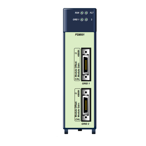
The PACSystems RX3i PROFINET Controller module,
IC695PNC001, connects a PACSystems RX3i controller to a
PROFINET network. It enables the RX3i controller to communicate
with IO-Devices on the network. The PNC provides all the functions,
services, and protocols required for certification as a PROFINET IO
Version 2.2 IO Controller, running at both 100Mbps and 1Gbps.
The PNC supports 10/100/1000Mbps Copper, 100/1000Mbps Multi-
mode Fiber, and 100/1000Mbps Single-mode Fiber. The network
can include media interfaces of more than one type. PROFINET
communications on the network require 100 and 1000 Mbps link
speed. 10Mbps cannot be used for PROFINET communications.
However, 10Mbps can be used for other types of Ethernet traffic,
such as ping, and telnet.
Features of the RX3i PNC include:
▪Full programming and configuration services for the PROFINET
Controller, VersaMax PROFINET Scanner (PNS) and third-party
IO-Devices using PROFICY Machine Edition.
▪Firmware upgrades using the WinLoader software utility.
▪Built-in Command Line Interface function that provides direct
monitoring and partial configuration via the module’s micro USB
port or using telnet.
Note: The USB port is for system setup and diagnostics only. It
is not intended for permanent connection.
▪Support for star, ring, and daisy-chain/line network topologies.
1
2
3
4
PNC001
ACTIVE
USB
OK
LAN
STATUS
CONFIG
USB
RESTART
IP ADDRESS
INTERFACE MAC
PORTS
FRONT
TO INSTALL, TORQUE TO
6 IN-LB. TO UNINSTALL,
REVERSE MOTION
3 4
1 2
!
▪Four switched Ethernet ports —two 8-conductor RJ-45 shielded twisted pair 10/100/1000 Mbps
copper interfaces and two Small Form-factor Pluggable (SFP) cages for user-supplied SFP
devices.
▪Support for media redundancy
▪Internal clock synchronized with the RX3i CPU for time-stamped diagnostics entries.
▪Restart pushbutton to manually restart the module without power cycling the system.
▪LEDs: OK, LAN, STATUS, CONFIG, ACTIVE, USB, and four Port LEDs.

GFK-2571A Chapter 1 Introduction 1-3
1
PROFINET Controller Specifications
PROFINET Support
PROFINET Version 2.2 General Class A IO-Controller
CPU Compatibility
Requires CPU315 or CPU320, with firmware version 7.0 or higher.
Power Requirements
3.3V: 0.5 A with no SFP devices installed
1.2 A maximum (2 SFP devices installed, 0.35 A per SFP device)
5V: 1.5 A maximum
Operating Temperature Range
0 to 60°C maximum surrounding air temperature without a fan.
A lower maximum temperature may be required depending on PNC
location and SFP population. Refer to ―Maximum Surrounding Air
Temperature Derating‖ on page 1-4.
Number of Port Connectors
Two RJ-45 and Two SFP Cages
(SFP devices not included, available separately.)
Micro USB Connector
One, for communication with a computer using Command Line Interface.
LAN
IEEE 802.2 Logical Link Control Class I
IEEE 802.3 CSMA/CD Medium Access Control 10/100/1000 Mbps
Maximum I/O Memory
128 Kbytes of combined input/output memory per PROFINET Controller
CPU Status Bits
32
PROFINET IO-Device Data
Update Rates on the
PROFINET Network
Configurable: 1ms, 2ms, 4ms, 8ms, 16ms, 32ms, 64ms, 128ms, 256ms
and 512ms
Number of IP addresses
One
Number of MAC Addresses
Five. One per external port and one internal.
System Maximum Limits
PROFINET Controllers per RX3i
CPU
4. Must be located in main rack. Cannot be located in a remote node.
IO-Devices per IO-Controller
64 per PROFINET Controller at maximum update interval. For limits at
shorter update intervals, refer to ―PNC Loading Limits‖ in chapter 3.
IO-Devices per Network
128 per network, spread across up to 8 IO-Controllers
IO-Devices per RX3i CPU
128 per RX3i CPU, spread across up to 4 PROFINET Controllers
IO-Controllers per network
8
Number of PROFINET Slots per
device
256
Number of PROFINET Subslots
per slot
256
Number of PROFINET
Submodules per RX3i CPU
2048
Programmer Limits
Number of IO-Controllers
128 (32 RX3i CPU targets × 4 IO-Controllers per RX3i CPU)
Number of IO-Devices
2048 (128 per network × 16 PROFINET networks)
Total number of devices
2176 (does not include backplanes, power supplies, or I/O modules)
Hot-swappable
Yes
For product standards, general operating specifications, and installation requirements, refer to the PACSystems RX3i
System Manual, GFK-2314.

1-4 PACSystems* RX3i PROFINET Controller Manual –December 2011 GFK-2571A
1
Operating Range for Surrounding Air Temperature
Baseline Installation
0 to 60°C surrounding air temperature under the following
installation:
▪12-slot panel mounted backplane
▪Two PNC modules in adjacent slots per backplane
▪1 GB Fiber SFPs
▪All four ports active
The following installation exceptions are cumulative:
Installation Exceptions
Reduces maximum operating temperature:
▪If 7 slot backplane, then reduce by 2°C
▪If air mounted (rack mount), then reduce by 2°C
▪If three or four PNCs per backplane, then reduce by 1°C
▪Either/or:
- If 100 MB Fiber SFPs installed, then reduce by 5°C
- If Copper SFPs operating at 1 GB, then reduce by 6°C
Increases maximum operating temperature to an upper limit of
60°C:
▪If only one PNC per backplane, then increase by 2°C
▪If PNC in non-adjacent slots, then increase by 1°C
▪If Copper SFP operating at 100MB, then increase by 4°C
▪If RJ45 ports unused, then increase by 0°C
▪If 16 slot backplane, then increase by 0°C
Example - Calculating Maximum Operating Temperature with Installation Exceptions
Baseline Installation 60°C
7 slot Backplane -2°C
Two PNC modules in non-adjacent slots +1°C
Copper SFPs operating at 1 GB -6°C
Maximum operating temperature after installation exceptions 53°C

GFK-2571A Chapter 1 Introduction 1-5
1
PROFINET Controller Module Controls and Indicators
The illustration below shows the front of the RX3i PROFINET Controller module and identifies its
controls and indicators.
LEDs:
1,2,3,4, OK, LAN,
STATUS, CONFIG
Heat sink screw
LEDs: USB COMM, ACTIVE
Micro USB Port
Restart Pushbutton
Labels
Ethernet Ports
1
2
3
4
PNC001
ACTIVE
USB
OK
LAN
STATUS
CONFIG
USB
RESTART
IP ADDRESS
INTERFACE MAC
PORTS
FRONT
TO INSTALL, TORQUE TO
6 IN-LB. TO UNINSTALL,
REVERSE MOTION
3 4
1 2
!
Ethernet Network Ports
The PROFINET Controller connects to a PROFINET network via one or more of its four external
switch ports. Two 8-conductor RJ-45 shielded twisted pair 10/100/1000 Mbps copper interfaces and
two Small Form-factor Pluggable (SFP) cages provide flexibility in media selection and the ability to
use redundant media for the PROFINET network. Use of redundant media must first be set up in the
module configuration. Chapter 6 provides additional information about redundant media.
The PROFINET protocol supported by the PACSystems RX3i PROFINET modules may be sent and
received over any of the four external ports.
The module is assigned five Ethernet MAC addresses: one for each of the four external Ethernet
ports and one for the internal switch.

1-6 PACSystems* RX3i PROFINET Controller Manual –December 2011 GFK-2571A
1
Port Status Indicators
Each external switch port has an associated link-up/link-down status bit that can be monitored by the
RX3i CPU to check the operating status of the port (see ―Status Reporting‖in chapter 5,
―Diagnostics,‖for information about the PROFINET Controller status bits). In addition, the four Port
LEDs on the front of the module provide a visual indication of the port status.
SFP Modules for Ethernet Ports
Each Small form-Factor Pluggable (SFP) cage on the bottom of a PROFINET Controller module is
capable of accepting a 10/100/1000 Mbps copper SFP, 100Mbps Single-Mode Fiber SFP, 100Mbps
Multi-Mode Fiber SFP, 1000Mbps Single-Mode Fiber SFP, or 1000Mbps Multi-Mode Fiber SFP
device. SFP devices can be removed/replaced during module operation. The RX3i PROFINET
Controller supports the SFP devices listed below. An SFP type other than those listed below may be
configured as a GENERIC SFP in Proficy Machine Edition. The RX3i PROFINET Controller will
attempt to operate with a generic SFP that identifies itself as an Ethernet SFP. Since SFP types
other than those listed below have not been validated, correct operation cannot be guaranteed.
SFP Type
Wavelength
(nm)
Media Type
Core Size
(μm)
Modal
Bandwidth
(MHz –Km)
Distance (m)
100BASE-FX1
1300
MMF
62.5
500
2 –2,000 (Full-
Duplex)
2 –400 (Half-
Duplex)
50
400
50
500
100BASE-LX10
1300
SMF
9
-
2 –10,000
1000BASE-SX
850
MMF
62.5
160
2 –220
200
2 –275
50
400
2 –500
500
2 –550
1000BASE-LX
1300
SMF
9
-
2 –10,000
1000BASE-ZX
1550
SMF
9
-
2 –70,000
10/100/1000BASE-T2
-
CAT5/CAT5e/CAT6
-
-
100 (maximum)
1GE Intelligent Platforms part number IC695SPF002
2GE Intelligent Platforms part number IC695SPC100

GFK-2571A Chapter 1 Introduction 1-7
1
Micro USB Port
The PROFINET Controller module has a micro USB port for connection to a computer running
Windows 2000, Windows XP, Windows Vista, or Windows 7. The USB port can be used to access
the PROFINET Controller’s Command Line Interface function using a terminal emulation application
such as HyperTerminal.
The Command Line Interface function can be used to monitor a PROFINET Controller module and
check its operation. If a problem occurs, the Command Line Interface can be used help determine
the cause.
A provided driver-install application is used to set up a computer to communicate with the USB port
(see chapter 2, Installation, for instructions).
Restart Pushbutton
The Restart pushbutton on a PROFINET Controller module can be used to manually restart the
module without cycling power. The restart operation starts when the pushbutton is released.
LEDs on the PROFINET Controller Module
The table below summarizes LED functions. More detailed information about error indications and
special blink patterns is given in chapter 2, Installation and chapter 5, Diagnostics.
OK
Indicates whether the module is able to perform normal operation.
LAN
Indicates network packets are being processed by the network interface (not just
passing through the embedded switch).
STATUS
Indicates the condition of the PROFINET Controller during normal operation. It
indicates whether an entry other than the startup event is present in the module’s
local log. STATUS can also indicate whether any of the MAC addresses are
invalid.
CONFIG
Indicates whether the module has received its configuration from the RX3i CPU.
ACTIVE
Indicates the status of PROFINET connections.
USB
Indicates activity on the USB port.
Port LEDs
Indicate link speed, link connection and link activity corresponding to the four
possible external Ethernet ports.

1-8 PACSystems* RX3i PROFINET Controller Manual –December 2011 GFK-2571A
1
System Limits
4 PROFINET Controller modules per RX3i CPU, connected to the same network or to
separate networks.
128 IO-Devices on the PROFINET network.
8 IO-Controllers per network
64 IO-Devices per PROFINET Controller
128 IO-Devices per network, spread across a maximum of 8 IO-Controllers
63/64/130 total devices per PROFINET network, depending on the topology:
oFor a network using ring topology, the maximum number of devices is 64 –consisting of
the PROFINET Controller plus up to 63 IO-Devices. If the ring uses Media Redundancy
Protocol, this means one Media Redundancy Manager and up to 63 clients.
oFor a network using star topology, the maximum number of devices is 65 –consisting of
the PROFINET Controller plus up to 64 IO-Devices.
oFor a network using line topology with two PROFINET Controllers, the maximum number
of devices is 130 (2 PROFINET Controllers plus 2 x 64 devices).
4 PROFINET Controllers per RX3i CPU node
128 IO-Devices per RX3i CPU Node, spread across up to 4 PROFINET Controllers
128 Kbytes of combined input and output memory per PROFINET Controller
Machine Edition Project Maximum Limits
With the above limits, the maximum number of PROFINET IO-Controllers and IO-Devices in a single
Proficy Machine Edition project is:
16 PROFINET IO Networks in a Proficy Machine Edition project
32 Proficy Machine Edition targets per Proficy Machine Edition project
128 IO-Controllers (32 RX3i CPU targets × 4 IO-Controllers per RX3i CPU Node)
2048 IO-Devices (16 PROFINET IO networks × 128 IO-Devices per network)
Total: 2176 Devices (not including backplanes, power supplies, IO modules, etc).

GFK-2571A Chapter 1 Introduction 1-9
1
PROFINET Networks for PACSystems
PROFINET is an open standard for industrial automation that is based on Industrial Ethernet. The
PROFINET IO framework allows the creation of I/O data exchanges between controllers and
distributed devices. It also allows configuration, parameterization, and diagnostics communication
between controllers and devices.
Note: The PROFINET Controller operates only in autonegotiate mode. All PROFINET bus
devices and switches that are connected to the PROFINET Controller should be
configured to use autonegotiation.
Basic System: One RX3i CPU and One PROFINET Controller using a
single port
Components of the RX3i PROFINET network consist of a PACSystems RX3i PNC module in the
RX3i main rack communicating with IO Devices on the PROFINET bus. The main RX3i rack can
include up to four PNCs, each communicating with its own high-speed network. IO Devices on the
network can include VersaMax PNS modules and a wide range of third-party devices. For example,
the illustration below shows a basic system with one PACSystems RX3i CPU node having one PNC,
and one PROFINET network with three VersaMax Scanners and one third-party IO-Device. Up to 64
IO-Devices can be installed on an RX3i PROFINET network. The VersaMax PNS and many types of
third-party IO-Devices interface multiple devices such as I/O modules to the PROFINET network.
IO-Device 1
IO-Device 2
IO-Device 64
3
rd
Party
IO-Device 3
RX3i CPU Node with
PROFINET Controller
PROFINET IO LAN
. . .
.

1-10 PACSystems* RX3i PROFINET Controller Manual –December 2011 GFK-2571A
1
Basic System: One RX3i CPU and One PROFINET Controller using
multiple ports
The illustration below shows a basic system with one PACSystems RX3i CPU node that has one
RX3i PROFINET Controller module controlling one PROFINET network. The network can connect
up to 64 compatible IO-Devices, including any combination of VersaMax PROFINET Scanners and
third-party IO-Devices.
This example shows one RX3i PROFINET Controller that is directly connected to four separate
IO-Devices in a Star topology. Although each IO-Device is connected to a separate Ethernet port on
the PNC, they are all on the same network segment (IO LAN 1). The IO-Devices in this example are
all VersaMax PROFINET Scanners, but third-party IO-Devices can also be used.
IO-Device
IO LAN 1
IO LAN 1
IO LAN 1
IO LAN 1
RX3i CPU Node
w/ one PNC
IO-Device
IO-Device
IO-Device

GFK-2571A Chapter 1 Introduction 1-11
1
Basic System: Third-Party Devices and PME Programmer
Third-party IO Devices can be used with the RX3i PROFINET Controller if their manufacturer
provides a GSDML file that can be imported into Proficy Machine Edition (PME). The GSDML file
defines the characteristics of the IO-Device and its I/O modules. Importing a third-party IO-Device
GSDML file and configuring third-party IO-Devices are described in chapter 3, and in the Proficy
Machine Edition online help.
After receiving a third-party device’s configuration, the RX3i PROFINET Controller connects to the
third-party IO-Device if the device is available, transfers the configuration to the device, and starts
exchanging I/O and alarm data with the device.
The next illustration shows a programmer connection (for configuration, user logic programming, and
monitoring), the concept of GSDML import, an optional external Ethernet switch, and the ability to
connect field buses to a PROFINET IO-Device. Third-party IO-Devices that have only one Ethernet
port may require the use of an external switch.
RX3i CPU Node
with PROFINET Controller
Import
Prog/Config Connection
Ethernet
(Optional)
Serial
3rd Party
GSDML File
Programmer (PME)
IO-Device
IO-Device
3rd Party
PROFINET
IO-Device
PROFINET IO LAN
Fieldbus Network
Industrial
Ethernet Switch
(Optional)

1-12 PACSystems* RX3i PROFINET Controller Manual –December 2011 GFK-2571A
1
Systems with One RX3i CPU and Two PROFINET Controllers
Both examples in this section show systems with one RX3i CPU that has two PROFINET Controller
modules. The PROFINET network can serve up to 63 IO-Devices (ring topology) or 64 IO-Devices
(in star topology).
Note that multiple PNCs in the same rack are not synchronized such that all PNCs are guaranteed to
power up at the same time. PNC configuration differences (SFPs, etc.) can cause variations in PNC
power up times.
If two (or more) PNCs are in a main rack and devices owned by one PNC are routed thru the switch
on a different PNC in the same rack, devices may show a Loss of Device fault followed by an
Addition of Device fault during RX3i powerup because the first PNC can power up before the second
PNC has enabled its Ethernet switch, causing the Loss of Device. Then when the second PNC
powers up, the device will show a Addition of Device fault. Devices will function normally once
added.
In the following example, both PROFINET Controllers are connected to the same network.
IO LAN 1
RX3i CPU Node with
2 PROFINET Controllers
IO-Device 1
IO-Device 2
IO-Device 3
IO-Device 4
IO LAN 1
IO LAN 1
NOTE:
Daisy-chain shown for clarity.
A star or ring topology
is preferred.

GFK-2571A Chapter 1 Introduction 1-13
1
In the following example, the two PROFINET Controllers are connected to separate networks. The
maximum number of IO-Devices with multiple PROFINET Controllers in the same RX3i controller
is 128.
IO LAN 1
RX3i CPU Node
w/ two PNCs
IO-Device
IO-Device
IO-Device
IO-Device
IO LAN 2
NOTE:
Daisy-chain shown for clarity.
A star or ring topology
is preferred.

1-14 PACSystems* RX3i PROFINET Controller Manual –December 2011 GFK-2571A
1
One RX3i CPU with Four Controllers on Separate Networks
This example shows a system with one RX3i CPU node containing the maximum of four RX3i
PROFINET Controllers, with each PROFINET Controller connected to a different network. In this
architecture, up to 128 IO-Devices are allowed, spread across the four networks. Up to 64 IO-
Devices can be controlled by any given PROFINET Controller.
Note that multiple PNCs in the same rack are not synchronized such that all PNCs are guaranteed to
power up at the same time. PNC configuration differences (SFPs, etc.) can cause variations in PNC
power up times.
If two (or more) PNCs are in a main rack and devices owned by one PNC are routed thru the
switch on a different PNC in the same rack, devices may show a Loss of Device fault followed by
an Addition of Device fault during RX3i powerup because the first PNC can power up before the
second PNC has enabled its Ethernet switch,causing the Loss of Device. Then when the second
PNC powers up, the device will show a Addition of Device fault.Devices will function normally
once added.
IO-Device
IO LAN 1
IO LAN 2
IO LAN 3
IO LAN 4
RX3i CPU Node
w/ four PNCs
IO-Device
IO-Device
IO-Device
IO-Device
IO-Device
IO-Device
IO-Device
NOTE:
Daisy-chain shown for clarity.
A star or ring topology is
preferred.
As in the other examples, third-party IO-Devices could be substituted for the VersaMax PROFINET
Scanners.
Table of contents
Other GE Controllers manuals

GE
GE ASTAT XL User manual

GE
GE C30 User manual

GE
GE Masoneilan 4700E User manual

GE
GE AF-600 FP Series User manual

GE
GE AF-650 GP Series User manual

GE
GE Multilin GEK-113000T User manual

GE
GE ARITECH FP400 Series User manual

GE
GE IC3645SR7A353E1 User manual

GE
GE PACSystems* RX3i User manual

GE
GE Multilin F650 User manual
Popular Controllers manuals by other brands

Estate Swing
Estate Swing E-S 1000D Series instruction manual

Sunricher
Sunricher SR-2808 user manual

ATESS
ATESS PBD250 user manual

Chziri
Chziri ZJR1 Series user manual

Mitsubishi Electric
Mitsubishi Electric MELSEC-F FX-USB-AW user manual

Johnson Controls
Johnson Controls TEC-2647-4 Installation & operation manual