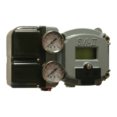
GE SVI II AP User manual

GE Oil & Gas
Masoneilan*
SVI* II AP Digital Positioner
Quick Start Guide (Rev. N)
GE Data Classification: Public

© 2015 General Electric Company. All rights reserved.
2 | =GE Oil & Gas
About this Guide
This Quick Start Guide applies to the following instruments and supported software:
SVI II AP and SVI II AP / AD with
Firmware version 3.1.1, 3.1.3, 3.2.1 and 4.1.1
ValVue suite version 2.40.0 or greater (including PRM Plug-In & AMS SNAP-ON)
DTM version 1.01.0 or greater
A handheld communicator with DD published for SVI II AP
The information contained in this manual, in whole or part, shall not be transcribed or copied without
GE’s written permission. In no case does this manual guarantee the merchantability of the positioner
or the software or its adaptability to a specific client needs.
Please report any errors or questions about the information in this manual to your local supplier or visit
www.geoilandgas.com/valves.
DISCLAIMER
THESE INSTRUCTIONS PROVIDE THE CUSTOMER/OPERATOR WITH IMPORTANT PROJECT-SPECIFIC
REFERENCE INFORMATION IN ADDITION TO THE CUSTOMER/OPERATOR’S NORMAL OPERATION
AND MAINTENANCE PROCEDURES. SINCE OPERATION AND MAINTENANCE PHILOSOPHIES VARY, GE
(GENERAL ELECTRIC COMPANY AND ITS SUBSIDIARIES AND AFFILIATES) DOES NOT ATTEMPT TO
DICTATE SPECIFIC PROCEDURES, BUT TO PROVIDE BASIC LIMITATIONS AND REQUIREMENTS CREAT-
ED BY THE TYPE OF EQUIPMENT PROVIDED.
THESE INSTRUCTIONS ASSUME THAT OPERATORS ALREADY HAVE A GENERAL UNDERSTANDING OF
THE REQUIREMENTS FOR SAFE OPERATION OF MECHANICAL AND ELECTRICAL EQUIPMENT IN PO-
TENTIALLY HAZARDOUS ENVIRONMENTS. THEREFORE, THESE INSTRUCTIONS SHOULD BE INTER-
PRETED AND APPLIED IN CONJUNCTION WITH THE SAFETY RULES AND REGULATIONS APPLICABLE
AT THE SITE AND THE PARTICULAR REQUIREMENTS FOR OPERATION OF OTHER EQUIPMENT AT THE
SITE.
THESE INSTRUCTIONS DO NOT PURPORT TO COVER ALL DETAILS OR VARIATIONS IN EQUIPMENT
NOR TO PROVIDE FOR EVERY POSSIBLE CONTINGENCY TO BE MET IN CONNECTION WITH INSTAL-
LATION, OPERATION OR MAINTENANCE. SHOULD FURTHER INFORMATION BE DESIRED OR SHOULD
PARTICULAR PROBLEMS ARISE WHICH ARE NOT COVERED SUFFICIENTLY FOR THE CUSTOMER/OP-
ERATOR'S PURPOSES THE MATTER SHOULD BE REFERRED TO GE.
THE RIGHTS, OBLIGATIONS AND LIABILITIES OF GE AND THE CUSTOMER/OPERATOR ARE STRICTLY
LIMITED TO THOSE EXPRESSLY PROVIDED IN THE CONTRACT RELATING TO THE SUPPLY OF THE
EQUIPMENT. NO ADDITIONAL REPRESENTATIONS OR WARRANTIES BY GE REGARDING THE EQUIP-
MENT OR ITS USE ARE GIVEN OR IMPLIED BY THE ISSUE OF THESE INSTRUCTIONS.
THESE INSTRUCTIONS ARE FURNISHED TO THE CUSTOMER/OPERATOR SOLELY TO ASSIST IN THE IN-
STALLATION, TESTING, OPERATION, AND/OR MAINTENANCE OF THE EQUIPMENT DESCRIBED. THIS
DOCUMENT SHALL NOT BE REPRODUCED IN WHOLE OR IN PART TO ANY THIRD PARTY WITHOUT
THE WRITTEN APPROVAL OF GE.
Copyright
All information contained herein is believed to be accurate at the time of publication and is subject to
change without notice.
Copyright 2015 by General Electric Company. All rights reserved. PN 055201-167 REV N

© 2015 General Electric Company. All rights reserved.Masoneilan SVI II AP Digital Positioner Quick Start Guide | 3
Contents
Safety Information ................................................................................... 7
Safety Symbols ............................................................................................................................7
SVI II AP Product Safety............................................................................................................................ 8
Installation and Set Up ............................................................................ 11
Introduction ...................................................................................................................................11
Using the Quick Start Guide................................................................................................................... 13
Single Acting Positioner............................................................................................................................ 14
Double Acting Positioner ......................................................................................................................... 15
Pushbuttons and Local Display............................................................................................................ 16
Pushbuttons ................................................................................................................................................. 16
ValVue* Software........................................................................................................................................ 20
ValVue Lite .................................................................................................................................................... 20
System Requirements .............................................................................................................................. 20
ValVue Full Trial Version .......................................................................................................................... 20
Mounting the SVI II AP............................................................................................................................... 21
Necessary Precautions ........................................................................................................................... 21
Mounting the SVI II AP on Rotary Valves ......................................................................................... 22
Travel Sensor Alignment ......................................................................................................................... 24
Mounting the SVI II AP on Reciprocating Valves ......................................................................... 25
Checking the Magnet ............................................................................................................................... 29
Installing the SVI II AP for Double- Acting Operation ................................................................. 30
Connecting the Tubing and Air Supply ............................................................................................. 33
Connecting the Air Supply ..................................................................................................................... 34
Wiring the SVI II AP..................................................................................................................................... 34
Connecting to the Control Loop .......................................................................................................... 35
Wiring Guidelines ....................................................................................................................................... 35
SVI II AP Setups ........................................................................................................................................... 36
Grounding Practices ................................................................................................................................. 36
Compliance Voltage in Single Drop Current Mode ..................................................................... 37
Verify Wiring and Connections ............................................................................................................ 37
Check Out, Configuration and Calibration .......................................... 39
Overview .........................................................................................................................................39
Check Out Procedures.............................................................................................................................. 39

© 2015 General Electric Company. All rights reserved.
4 | GE Oil & Gas
Inspecting Actuator, Linkages, or Rotary Adapter ......................................................................40
Verifying Mounting and Linkage Adjustment ...............................................................................40
Checking the Magnet ...............................................................................................................................40
Checking the Air Supply ..........................................................................................................................42
Checking the Electronic Module Connections ..............................................................................42
Operational Checkout...............................................................................................................................44
Connecting to the Current Source .....................................................................................................44
Powering Up the SVI II AP .......................................................................................................................44
Configuration ................................................................................................................................................46
Configuration with Pushbuttons .........................................................................................................46
Viewing Status Messages .......................................................................................................................48
VIEW DATA Settings ..................................................................................................................................48
Calibration ......................................................................................................................................................49
Check-out with a HART® Handheld Communicator .................................................................53
Maintenance .............................................................................................. 55
SVI II AP Maintenance ...............................................................................................................................55
Repair ...............................................................................................................................................................55
Tools Needed for Cover Replacement ..............................................................................................55
Display Cover Removal and Installation .........................................................................................56
Specifications and References ............................................................... 59
Physical and Operational Specifications.......................................................................... 59
Hazardous Location Installation..........................................................................................................66
Spare Parts.....................................................................................................................................................83
Optional Switch Load Limits ................................................................... 87
General Configuration Notes.................................................................................................................87
Checking Switch Operation....................................................................................................................89
ValVue Commands ....................................................................................................................................89

Document Changes
Version/Date Changes
H/12-2010 Changes ES-699 doc to Rev N. See Appendix A
J/3-11 Changes ES-699 doc to Rev P. See Appendix A
K/12-2011 Added description and procedures relevant to introduction of the high
throughput version. ES-699 updated.
L/10-2012 Changed the specifications to reflect single acting supply pressure of up
to 100 and double-acting up to 150 psi.
Entered edits from Sandro Esposito and Stephane Leledy.
M/09-2013 Added the Load Limits sections and a cross reference to it from the wiring
installation.
Updated ES-699 to Rev. Y.
N/10-2015 Updated the Load Limits section.
Updated ES-699 to Rev. AA.
Updated Disclaimer statement.
Added information on position retransmit switches.
Removed Remote Positioner Installation.
© 2015 General Electric Company. All rights reserved.Masoneilan SVI II AP Digital Positioner Quick Start Guide | 5

Page Left Blank Intentionally

Masoneilan SVI II AP Digital Positioner Quick Start Guide =| 7
© 2015 General Electric Company. All rights reserved.
This section provides safety information and defines the documentation symbols.
Safety Symbols
Indicates a potentially hazardous situation, which if
not avoided could result in serious injury or death.
Indicates a potentially hazardous situation, which if
not avoided could result in instrument or property
damage, or data loss.
Indicates important facts and conditions.
WARNING
CAUTION
NOTE
1. Safety Information

© 2015 General Electric Company. All rights reserved.
8 | =GE Oil & Gas
SVI II AP Product Safety
The SVI II AP digital valve positioner is intended for use with industrial compressed air or, natural
gas systems only.
NOTE See “Hazardous Location Installation” on page 66 for natural gas
safety information.
Ensure that an adequate pressure relief provision is installed when the application of system
supply pressure could cause peripheral equipment to malfunction. Installation must be in accor-
dance with local and national compressed air and instrumentation codes.
General installation, maintenance or replacement
Products must be installed in compliance with all local and national codes
and standards by qualified personnel using safe site work practices.
Personal Protective Equipment (PPE) must be used per safe site work
practices.
Ensure proper use of fall protection when working at heights, per safe site
work practices. Use appropriate safety equipment and practices to prevent
the dropping of tools or equipment during installation.
Under normal operation, compressed supply gas is vented from the SVI II AP
to the surrounding area, and may require additional precautions or
specialized installations.
Intrinsically Safe Installation
Products certified as explosion proof or flame proof equipment or for use in intrinsically safe in-
stallations MUST BE:
Installed, put into service, used and maintained in compliance with national
and local regulations and in accordance with the recommendations
contained in the relevant standards concerning potentially explosive
atmospheres.
Used only in situations that comply with the certification conditions shown
in this document and after verification of their compatibility with the zone of
intended use and the permitted maximum ambient temperature
Installed, put into service and maintained by qualified and competent
professionals who have undergone suitable training for instrumentation
used in areas with potentially explosive atmospheres.
WARNING Before using these products with fluids/compressed gases other
than air or for non-industrial applications, consult the factory.
This product is not intended for use in life support systems.

Masoneilan SVI II AP Digital Positioner Quick Start Guide =| 9
© 2015 General Electric Company. All rights reserved.
WARNING Under certain operating conditions, the use of damaged
instruments could cause a degradation of the performance of the
system which may lead to personal injury or death.
Under certain operating conditions the SVI II AP High Flow unit
can produce noise levels greater than 85 dBA. Perform proper site
monitoring and testing to verify the need for engineering or
administrative controls to eliminate or reduce hazardous noise
levels.
Installation in poorly ventilated confined areas, with any potential
of gases other than oxygen being present, can lead to a risk of
personnel asphyxiation.
Use only genuine replacement parts which are provided by the manufacturer, to guarantee that
the products comply with the essential safety requirements of the European Directives.
Changes to specifications, structure, and components used may not lead to the revision of this
manual unless such changes affect the function and performance of the product.

This page intentionally left blank.

Masoneilan SVI II AP Digital Positioner Quick Start Guide =| 11
© 2015 General Electric Company. All rights reserved.
Introduction
The SVI II AP provides for reliable operations of control valves with utmost simplicity in setup and
commissioning. It is uniquely equipped with a non-contact travel sensor allowing for accurate
positioning and maintenance free operations. The pneumatic train of the SVI II AP is a dual-stage
amplification system with stainless steel wetted parts for durability. Intrinsically Safe, Flameproof
and Explosion proof designs are offered as standard. The High Flow version is capable of 2.2 Cv
air throughput. Some of the SVI II AP options include marine grade construction, local indicating
LCD with push buttons for local calibration, position transmitter, discrete outputs, double-acting
(not available for the High Flow version) and a remote mount position-sensing mechanism. Using
HART®eDDL and FDT-DTM technologies, the Masoneilan SVI II AP digital valve positioner pro-
vides interoperability with leading control systems suppliers.
Figure 1 SVI II AP
2. Installation and Set Up

© 2015 General Electric Company. All rights reserved.
12 | =GE Oil & Gas
Figure 2 SVI II AP Components
Figure 3 SVI II AP High Flow Components
SVI II AP Cover SVI II AP Assembled
Electronics
Module
Pneumatic Train and
Cover (I/P Module, Relay)
Manifold
Pneumatic Relay
I/P
SVI II AP Cover
Electronics
Module
Cover
Relay
I/P
Manifold
(I/P Module)

Masoneilan SVI II AP Digital Positioner Quick Start Guide =| 13
© 2015 General Electric Company. All rights reserved.
Using the Quick Start Guide
The SVI II AP Quick Start Guide is intended to help an experienced field engineer install, setup, and
calibrate an SVI II AP in an efficient manner. This document provides basic installation and setup
instructions and is not intended to replace the in-depth information contained in the SVI II AP In-
struction Manual. If you experience problems that are not documented in this guide refer to the
SVI II AP Instruction Manual, call your local representative, or go to www.ge-energy.com/valves.
Sales offices are listed on the last page of this document
The steps necessary to complete the SVI II AP installation and software setup are outlined in
Table 1.
Table 1: SVI II AP Installation Steps
Step No. Procedure Reference
1Attach mounting bracket to the actu-
ator.
See page 21 for rotary valve and
reciprocating valve instructions.
2Install the SVI II AP magnetic assem-
bly (rotary valves only).
See page 21 for instructions.
3Assemble the SVI II AP on the bracket
that is mounted to the valve actuator.
See page 21 for rotary valve and
reciprocating valve instructions.
4
Install the Remote Position Sensor, if
necessary.
See Masoneilan Valve Solutions
Remote Position Sensor Quick
Start Guide (GEA31195 or P/N
011525100-888-0000) for
instructions. Use GEA or P/N
when searching on the download
website).
5Connect the pneumatic tubing to the
SVI II AP.
See page 33 for instructions.
6Connect the air supply to the SVI II AP. See page 34 for instructions.
7
Connect the positioner to the HART®
Control Loop segment by installing
the SVI II AP wiring.
See page 35 for instructions.
8
Configure/calibrate using ValVue*. See page 46 and page 49 for
instructions.
Configure/calibrate using a HART®
Hand Held Communicator.
See page 53 for instructions.

© 2015 General Electric Company. All rights reserved.
14 | =GE Oil & Gas
WARNING Failure to adhere to the requirements listed in this manual may
cause loss of life and property.
Before installing, using, or carrying out any maintenance tasks
associated with this instrument, READ THE INSTRUCTIONS
CAREFULLY. Refer to “Hazardous Location Installation” on page A-
66 of this guide for detailed instructions.
Single Acting Positioner
The supply and output connections for the SVI II AP, located on bottom of the pneumatic block,
are tapped 1⁄4" NPT. The output port 1 is toward the front while the supply is toward the back.
Two pressure gauges, output on top, supply port on bottom, are located on the front of the pneu-
matic block.
The supply and output connections for the SVI II AP High Flow (Figure 5 on page 15), located on
bottom and leftside of the pneumatic block, are tapped 1⁄2" NPT.
Maximum allowable air supply pressure to the SVI II AP varies according to actuator, valve size,
and valve type. Refer to the serial plate of the valve to know the specified supply pressure; it must
never be less than the maximum spring pressure +5 psi.
Figure 4 Air Ports on Single Acting Positioner
Output
Supply

Masoneilan SVI II AP Digital Positioner Quick Start Guide =| 15
© 2015 General Electric Company. All rights reserved.
Figure 5 SVI II AP High Flow Air Ports on Single Acting Positioner
Double Acting Positioner
Connect Output 1, labeled(I) to the inlet port of the actuator and Output 2, labeled (II) to
the opposing actuator port (see Figure 6).
Figure 6 Air Ports on Double Acting Positioner
Output
Supply
Output I
Supply
Output II

© 2015 General Electric Company. All rights reserved.
16 | =GE Oil & Gas
Pushbuttons and Local Display
This section covers the optional local interface consisting of the LCD alphanumeric display and
pushbuttons. Operation of the SVI II AP Digital Valve Positioner as a local device is controlled
through the optional device-mounted pushbuttons and digital display, shown in Figure 7 on
page 17. Using the display you can read the input signal, valve position, and actuator pressure.
The display sequences from one variable to the next every 1.5 seconds.
Using the pushbuttons you can exit from operating mode at any time and step through a menu
structure to perform a wide range of manual operation, calibration, configuration, and monitor-
ing functions that are described later in this section. ValVue is used to perform all diagnostics
functions. The pushbuttons do not support diagnostics functions.
The SVI II AP has two operational modes: Normal Operating Mode and Manual Mode and two set-
up modes, Configuration and Calibration. The SVI II AP also has two modes for handling of faults
and power-up: Reset and Failsafe. When commissioning or checking a control valve with SVI II
AP fully installed the following steps are recommended:
Change mode to Manual mode
Examine and adjust all CONFIGuration items
Enter Calibration mode
Run STOPS to automatically calibrate stroke
Run autoTUNE to set dynamic response
Examine the device STATUS
Introduce manual set point changes to verify dynamic performance
Pushbuttons
The local pushbuttons are located behind a hinged cover, directly below the display window. To
open the cover loosen the screw and swing the cover down. Always re-fasten the cover after use
to protect the pushbuttons from environmental contamination.
The three pushbuttons perform the following functions:
Left Button - Marked with *,permits you to select or accept the value or
parameter option currently displayed.
Middle Button - Marked –,permits you to move back through the menu
structure to the previous item in the menu or decrement the value currently
shown in the digital display. When used to decrease a displayed value,
holding the button down causes the value to decrease at a faster rate.

Masoneilan SVI II AP Digital Positioner Quick Start Guide =| 17
© 2015 General Electric Company. All rights reserved.
Right Button - Marked +, permits you to move forward through the menu
structure to the next item in the menu, or to increment the value currently
shown in the digital display. When used to increase a displayed value
holding this button down causes the value to increase at a faster rate.
NOTE When an exclamation point (!) appears in the SVI II AP display
window, it indicates that there is instrument status available.
Figure 7 SVI II AP Display Pushbuttons
*+
-
(Select) (Forward)
(Back)

© 2015 General Electric Company. All rights reserved.
18 | =GE Oil & Gas
Pushbutton Locks and Configuration-Lock Jumper
Before performing any of these functions with the local display you must first ensure that the
pushbuttons are placed in the unlocked mode using ValVue Lite. The positioner is provided in the
unlocked mode. See ValVue documentation for more details.
The SVI II AP offers several levels of accessibility. It may be desirable, after initial setup, to lock the
pushbuttons so that the SVI II AP parameters cannot be inadvertently changed by the buttons.
Several levels of pushbutton locks are provided.
Table 2: Pushbutton Lock Security Level
Level Access
Security Level 3 Allow Local Buttons: Buttons on the SVI II AP are fully enabled.
Security Level 2 Lock Out Local Calibration and Configuration: Use the buttons to per-
form operations in normal operating mode and manual mode. Do not
go to configure or calibrate mode.
Security Level 1 Lock Out Local Manual: Examine variables in normal operating mode
but do not put the valve in manual operating mode. Access to cali-
brate or configure modes is not available.
Security Level 0 Lock Out All Buttons: The buttons are disabled (level 0).

Masoneilan SVI II AP Digital Positioner Quick Start Guide =| 19
© 2015 General Electric Company. All rights reserved.
Hardware Configuration Lock
Additional security is achieved using the hardware configuration-lock jumper shown in Figure 8.
When set to the secure position, shorting the two-pin header, configuration and calibration are
not permitted by the local interface or by remote communications. Pushbuttons, ValVue and
handheld are locked out, except to examine configuration, calibration, and position. This is sim-
ilar to Security Level 1 shown in the Pushbutton Lock Security Level table.
Figure 8 Connections to Electronics Module (via Terminal Board)
Display
Remote
Process Variable
Position Retransmit
Position
Input
Configuration Lock
Jumper
4- 20 mA
Input Signal
Solid State Switch SW #1
Solid State Switch SW #2
Sensor

© 2015 General Electric Company. All rights reserved.
20 | =GE Oil & Gas
ValVue* Software
The SVI II AP is shipped with a free version of ValVue Lite and a trial version of ValVue.
ValVue Lite
ValVue Lite software is shipped with each SVI II for positioner calibration and configuration. Val-
Vue Lite software is offered without registration. It provides sufficient functionality to fully com-
mission, configure, and start up a positioner on a control valve.
System Requirements
ValVue Lite runs on IBM compatible computers. Minimum requirements for all versions of ValVue
software are Windows®XP SP3, Windows®Server 2003 SP2, Windows®Server 2008, Windows®
7, 64 MB RAM, a serial or USB port connected to a HART®modem, and a CD-ROM drive.
ValVue Full Trial Version
The SVI II AP comes with a copy of ValVue Trial Version software that can be used for sixty days
without a license. After the 60-day trial period, ValVue must be registered. ValVue, full version,
provides advanced diagnostic, maintenance capabilities and basic calibration and configura-
tion for the SVI II AP. SVI II AP performs valve diagnostics and displays stroking speed, step re-
sponse, cumulative travel, cycles, and operation in near-closed position. The software stores test
results for comparison with future results for predictive maintenance. Password protected ac-
cess to remote instruments is set up with administration features. The fully licensed ValVue soft-
ware is available as an upgrade.
Table of contents
Other GE Controllers manuals
Popular Controllers manuals by other brands

BTF LIGHTING
BTF LIGHTING SP107E instructions

Watlow
Watlow EZ-ZONE PM Express user manual

Venmar
Venmar 40455 Installation and owner's guide

Carel
Carel WB000S series quick start guide

Vacon
Vacon 100X series Installation and maintenance manual

Mitsubishi Electric
Mitsubishi Electric MELSEC Q Series user manual