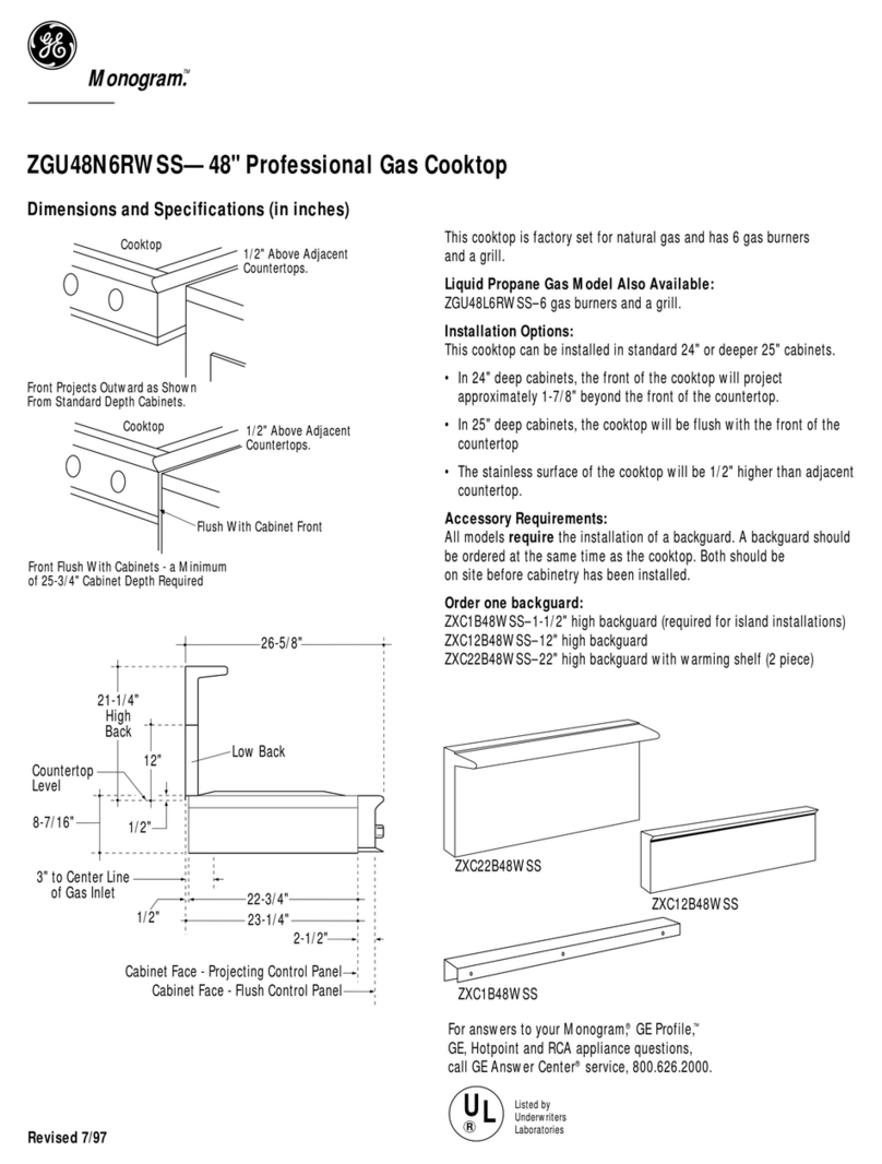
GE ZGU484LGP6SS User manual

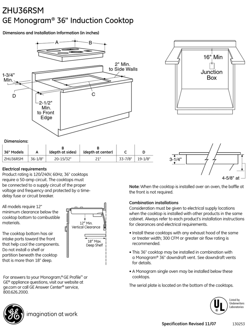
Installation
Instructions
36" and 48"
Professional Rangetops
Tables de cuisson
professionnelles de 36" (91 cm)
et de 48" (122 cm)
Instructions d'installation
La section fran_aise commence 6 la page 18
Estufas profesionales
de 36" (91 cm) g 48" (122 cm)
Instrucciones de instalaci6n
La secci6n en espa_ol empieza en la p6gina 34
131-i0691-21
06-09JR

Safetg Information
BEFORE YOU BEGIN
Read these instructions completely and carefully.
•IMPORTANT- soretheseinstructionsfor
Iocol inspector's use.
•IM PORTANT- Observeoligoverning
codes ond ordinonces.
• Note to Installer- Be sure to leove these
instructions with the Consumer.
• Note to Consumer- Keep these instructions
with LlOUrOwner's Monuol for future reference.
• Completion Time - I to :3hours.
• Proper instollotion is the responsibility of the
instoller. Product foilure due to improper
instollotion is not covered under the worrontLl.
See Owner's Monuol for worrontLl informotion.
WARNING
This opplionce must be properlLl grounded.
See "Electric SupplLl."
For Monogrom Iocol service in LlOUroreo,
1.800.444.1845.
For Monogrom Service in Conodo, coil
1.800.561.:3344.
For Monogrom Ports ond Accessories, coil
1.800.626.2002.
If LlOUreceived o domoged rongetop, LlOUshould
contoct LlOUrdeoler.
In the Commonwealth of Massachusetts:
• This product must be instolled bLl olicensed
plumber or gos fitter.
• When using boll tLlpe gos shut off volves, theLl
sholl be T-hondle type.
• A flexible gos connector, when used, must not
exceed :3feet.
If sold outside the U.S.and Canada:
.AWARNING: ifyouwishtouse this
product with Liquefied Petroleum (LP) gas
containing greater than 10% butane, gou
must purchase the butane conversion kit
#WB28K10589. To order, please call
1.888.664.8403 or 1.787.276.4051.
Vent hood Combinations:
It is recommended thot these rongetops be installed
in conjunction with u suitable overhead vent hood.
• Install u hood with at least 1200 CFM above u 48"
wide rangetop.
• Install u hood with at least 600 CFM above u :36"
rongetop.
Due to the high heat cupucitg of this unit, particular
attention should be paid to the hood and ductwork
installation to assure it meets local building codes.
WARNING:
Cleoronces to horizontol surfoces obove the
rongetop, meosured to the cooking surfoce:
• Instollotions without o hood require 48" minimum
to combustibles.
• A custom hood instollotion with exposed
horizontol combustibles surfoces must hove
on Auto-On feoture.
• For other instollotions with o hood, refer to hood
instollotion instructions for specific hood
cleoronces.
- CAUTION:
These rongetops ore extremely heovLl. Due to the
weight ond size of the rongetop ond to reduce the
risk of personol injurLl or domoge to the product:
TWO PEOPLEARE REQUIRED FOR PROPER
INSTALLATION.
Instollotion must conform with Iocol codes. In the
obsence of Iocol codes, the rongetop must complg
with the Notionol Fuel Gos Code, ANSIZ223.1/
NFPA 54, Iotest edition ond Notionol Electricol Code
ANSI/NFPA 70 Iotest oddition. In Conodo, instollotion
must conform with the current Noturol Gos
Instollotion Code, CAN/CGA-B149.1 or the current
Propone Instollotion Code, CAN/CGA-B149.2, ond
with Iocol codes where opplicoble. This rongetop hos
been design-certified bg CSA Internotionol occording
to ANSI Z21.1, Iotest edition ond Conodion Gos
Associotion occording to CAN/CGA-I.1 Iotest edition.
Leok testing of the opplionce sholl be conducted
occording to the monufocturer's instructions.

Design Information
CONTENTS
Design Information
Models Available ......................................................................3
Backsplash Accessories ......................................................3
Product Dimensions and Clearances
for 48" Wide Models ..............................................................4
Product Dimensions and Clearances
for 36" Wide Models ..............................................................5
Installation Options ..............................................................6
Installation Preparation
Tools and Materials Required ..........................................7
Power Supply Locations ....................................................7
Remove Packaging ................................................................8
Installation Instructions
Step 1, Cut the Countertop Opening ..............................9
Step 2, Install the Rangetop ............................................10
Step 3, Connect Rangetop to Gas ................................10
Step 4, Connect Electrical ..................................................
Step 5, Check Burners ........................................................
Finalize Installation ................................................................
Installation Checklist ............................................................
Install the Rangetop Backsplash Accessory ..........12
Install the AdJustable
Backsplash Accessory ................................................13, 14
Gas Conversion .............................................................. 15117
MODELS AVAILABLE
Monogram rangetops are factory set for natural
gas or LPgas. Order the model for your installation
situation.
48" Natural Gas Models:
ZGU484NG - 4 gas burners, grill and griddle
ZGU486NR- 6 gas burners and grill
ZGU486ND - 6 gas burners and griddle
48" LP Gas Models:
ZGU484LG - 4 gas burners, grill and griddle
ZGU486LR - 6 gas burners and grill
ZGU486LD - 6 gas burners and griddle
36" Natural Gas Models:
ZGU364ND - 4 gas burners and griddle
ZGU364NR- 4 gas burners and grill
ZGU366N - 6 gas burners
36" LP Gas Models:
ZGU364LD - 4 gas burners and griddle
ZGU364LR - 4 gas burners and grill
ZGU366L- 6 gas burners
BACKSPLASH ACCESSORIES
All models require 12" minimum clearance
to a vertical combustible surface at the rear.
If clearance is less than 12", the entire surface
of the back wall above the countertop and the full
width of the rangetop must be protected bLl a
backsplash. The backsplash must be constructed
of non-combustible material, such as metal,
ceramic tile, brick, marble or other stone.
Two Backsplash Accessories Available:
• The 12" high stainless steel backsplash accessory
is available. Use this backsplash in combination
with a custom, non-combustible backsplash built
beyond the 12" height. The combined height
of the backsplash accessory and the custom
backsplash must reach the bottom of a hood,
or when there is no hood, to 48" above
the cooking surface.
• An adjustable 30" to 36" high backsplash with shelf
is also available. This backsplash fills in the space
between the top of the rangetop and the bottom
of the hood. The shelf is positioned so that
heat lamps from the bottom of a Monogram
professional hood are directed towards the shelf.
12"HighBacksplash
ZX12B48PSS,for 48"wide ranget0ps
ZX12B36PSS,for 36"wide ranget0ps
30"to36"AdjustableHeightBacksplash
With Shelf
ZXADJB48PSS,for48"wideranget0ps
ZXADJB36PSS,for36"wideranget0ps
Design Information
PRODUCT DIMENSIONS AND CLEARANCES FOR 48" MODELS
......._ 27-1/2"to
...... Frontof
4 ...........................47-7/8"__ gu nose
8-1/2"
Height
Locategas
inlet onback
wall or on
floor2" from
backwall.
UniversalUtility Locations
2"
17"_
16"
-AWARNING:
Installations without a hood
require 48" minimum to combustibles
above the rangetop. A custom hood
installation with exposed horizontal
combustible surfaces must have
an Auto-On feature. Refer to hood
installation instructions for specific
hood clearances.
The surface of the entire back wall
above the countertop and below
the hood must be covered with
a non-combustible material such
as metal, ceramic tile, brick, marble
or other stone.
13"Max.
i
18"Min.
t
48" Minimum
to Combustibles
........46-1/4"
o
i
material
22-3/4"Min.
\\\\12"Minimumto
AdjacentWall
\
12"Minimum
-- EachSide 7/8" f 2-1/2"
J
*The opening between a 4" high backsplash must be 48"
to allow the rangetop to slide back against the wall.
ADDITIONAL CLEARANCES:
Allow 12" minimum clearance to an adjacent wall on
each side.
Working areas adjacent to the rangetop should have
18" minimum clearance between countertop and the
bottom of the wall cabinet.
12"Minimumto
Combustiblesor0" to
non-combustiblematerial
abovethecookingsurface
48" Min. to
Combustibles
0" l
Clearance
4

Design Information
PRODUCT DIMENSIONS AND CLEARANCES FOR 36" MODELS
i
35-7/8"Width ........._ 27-1/2"to
Frontof
4........................... "" Bullnose /
8-1/2"
Height
Locategas
inleton back
wall or on
floor2" from
backwall.
Universal Utility Locations
-&WARNING:
Instollotions without o hood
require 48" minimum to combustibles
obove the rongetop. A custom hood
instollotion with exposed horizontol
combustible surfoces must hove
on Auto-On feoture. Refer to hood
instollotion instructions for specific
hood cleoronces.
The surfoce of the entire bock woll
obove the countertop ond below
the hood must be covered with
o non-combustible moteriol such
os metol, ceromic tile, brick, morble
or other stone.
18"Min.
1
48" Minimum
to Combustibles
.......35"22-3/4" Min.
I'"'"i2" Minimumto
AdjacentWall
12"Minimum
EachSide
*The opening between o 4" high bocksplosh must be 36"
to ollow the rongetop to slide bock ogoinst the woll.
ADDITIONAL CLEARANCES:
Allow 12" minimum cleoronce to on odjocent woll on
eoch side.
Working oreos odjocent to the rongetop should hove
18" minimum deoronce between countertop ond the
bottom of the woll cobinet.
12"Minimumto
Combustiblesor0" to
non-combustiblematerial
abovethe cookingsurface
48" Min. to
Combustibles
0" l
Clearance

Design Information
INSTALLATION OPTIONS
8"
Countertop 8-1/2"
Level Height
Backedge
of chamfer
-,4............................................................................................................................................28-13/16" ..................................................................................................................................
ToFrontof Control Knobs
27-1/2" ...............................................................................................................................................................
ToFrontof £ullnose
* Hinimum cabinet cutout depth from
the back of the rear trim to the back
finished edge ofthe control panel-
typically, the minimum cabinet depth
(front to back). Haximum cabinet cutout
depth is 26" minus the countertop
overhang.
Finishedback edge
of control panel
I
6-1/2" _i_
U ....
5-1/4" !_
7-1/4"
....................* 23-1/2" ........................................................................................................................................._-
26-3/4" _-
TOFrontof Control Panel
t Includethe overhangofthe reartrim when countertop continuesbehindthe product.
Theoverhangisdecorativeonlg.Theweight oftherangetop isfullgsupported bgthesidetrims.
1/2"
?Countertop
Level
t 3/32"
1-3/1B"
........1-1/32"
ToPipeStub
Center
** Haximum countertop cutout depth
from the back ofthe rear trim
to the back edge of chamfer at the
sides of the control panel - tgpicallg,
the maximum countertop cutout depth
(front to back).Hinimum countertop
cutout depth is 25-1/4".
Rangetop
1/2" AboveAdjacent
Countertops
Rangetop
1/2" AboveAdjacent
Countertops
Control panel projects forwards from
standard depth cabinets. Front of deep cabinets can align with control
panel beveled edge.

Installation Preparation
TOOLS REQUIRED
SaberSaw
MeasuringTape
Carpenter'sSquare
SafetyGlasses
Phillips#2 Screwdriver
Level
Drilland
AppropriateBits
AdjustableWrench
1/4"DriverorWrench
HandTruck
MATERIALS PROVIDED
Hold-Down Regulator
Strap
MATERIALS REQUIRED (not provided)
Shut-OffValve
Joint PipeFittings
Sealant
5-foot maximum length, 5/8" O.D.CSA-approved
flexible metal gassupply
(3-foot maximum length in Massachusetts only)
NOTE: Purchasenew flexible line; do not use
previously usedflexible gas line.
POWER SUPPLY LOCATIONS
Gas Supplg:
• The natural gas models are designed to operate at 5"
water column pressure. For proper operation, the
pressure of the natural gas supplied to the regulator
must be between 7" and 13" water column.
• The LP models are designed to operate at 10" water
column pressure. For proper operation, the pressure
of the LPgas supplied to the regulator must be between
11" and 13"water column.
• Locate the pipe stub on the back wall or floor
(see"Product Dimensions and Clearances"). Use 5-foot
maximum length, 5/8" O.D.flexible gas supply line
(3-foot in Massachusetts).
• Install a manual shut-off valve in the gas line
(not provided), in an easily accessible location. Make sure
the homeowner knows where and how to shut off the gas
supply to the rangetop.
Electric Supplg:
These rangetops must be supplied with 120 volt, 60 Hz.,
and connected to a dedicated, properly grounded branch
circuit protected by a 15 amp circuit breaker or time
delay fuse.
The power cord of this appliance is equipped with a
three-prong (grounding) plug which mates with a standard
three-prong grounding wall receptacle to minimize the
possibility of shock hazard from this appliance.
If the electrical service provided does not meet the above
specifications, it is recommended that a licensed electrician
install an approved outlet.
DO NOT,UNDERANY
CIRCUMSTANCES,CUT
ORREMOVETHETHIRD
(GROUND)PRONGFROM
THE POWERCORD.
DO NOTUSEAN EXTENSION
CORDWITH THISAPPLIANCE.
• Locate the electric supply
Recep[acleBoxCoverPlate
ThreeProngPlug
\\
_Three ProngReceptacle
within the area shown or within reach of the rangetop's
four-foot power cord.
• To avoid tangling cord with items stored in the cabinet,
locate the receptacle on rear wall, inside the cabinet.

Installation Preparation
REMOVE PACKAGING
- CAUTION
Stand clear. The ends of the cut metal banding mag
snap toward gou.
• Cut the metal banding.
• Remove packaging tape and foam.
Dispose of packaging materials properlg.
• Remove grill/griddle covers, grill grate and burner
grates.
• Lift out cast-iron griddle flue cover, grease
troughs and pads.
• Cut the ties holding the grill grate to the grill frame.
GriddleFlueCover
Ties _eTroughs
• Lift off burner caps and remove foam pad,
then lift off burner heads and remove foam pad.
RemoveFoamPads

Installation
STEP 1
Allow Additional
Clearance Below
the Rangetop Burner
Box for the Regulator
and Gas Connections
CUT THE COUNTERTOP OPENING
vai abe
A lash ..............._ to36"
BackSP 12"
48"widemodelsare designedto fit in48"or wider basecabinets
Measure carefullu when cutting the countertop.
Hake sure sides of the opening are parallel.
• Allow 8" free space below the top surface of the countertop.
• Allow additional clearances below the burner box
to install the regulator and make house supplu
connections. Use a 90° elbow to route the gas
connections and limit interference with drawers
or other cabinetru features.
•These rangetops are designed to hang from
the countertop bu their side flanges.
• Smooth anu rough edges on the countertop before
installing the rangetop.
- Formica countertop edges must be finished.
The countertop must be strong enough to support
the weight of the rangetop.
Allow Additional
ClearanceBelow
[he RangetopBurner
Boxfor the Regulator
andGasConnections
..............:'_' _ 3o"
V8 au
Alash ................_' to36"
8-I/2"
z1/2" 2-1/2"
36"widemodelsaredesignedtofit in36"orwiderbasecabinets
Cutout Opening with False Bottom
Dimensions
A (Dia.) B C D
36" Rangetop 7-3/8" 1-1/2" 7-1/2" 11-1/8"
48" Rangetop 8-1/4" 1-1/2" 7-1/2" 11-1/8"
• You con construct the cutout with a false bottom to
conceol the bottom of the rangetop.
- Build the folse bottom using o solid moteriol; cut o
7-1/2" x 11-1/8" hole in the left reor corner for the gos
inlet ond power cord cleoronces.

Installation
STEP 2 INSTALL RANGETOP
• Slide the rangetop into the opening. Make sure
the rangetop is evenly seated and supported.
• A hold-down strap with screws is provided to
secure the rangetop to the rear or side cabinet
walls.
• Remove the hold-down strap from the back
of the rangetop. Attach one end of the strap
to the back of the rangetop.
• Secure the other end of the strap as high as
possible to the cabinet back wall or adjacent
cabinet. Keep the strap as short as possible for
better security.
BackWall
H01d-D0wn
Strap
Locationand
Attachment
STEP 3 CONNECT RANGETOP TO GAS
-AWARNING
Do not use a flame to check for gas leaks.
A manual shut-off valve must be installed where
it will be accessible.
Assure that gas is turned off at the shut-off
valve.
• Install the supplied pressure regulator onto the end
of the gas inlet.
• You can install a 90 ° elbow (not provided) onto the
gas inlet and route the gas connections to avoid
interference with drawers or other cabinetry
features. However, it is not recommended because
it will result in a drop in gas pressure.
• Make sure the regulator is installed in the right
direction. See arrow on the underside of the
regulator.
NOTE: Instead of using solid piping to connect
to pressure regulator, an approved flexible metal
appliance connector may be used between the pipe
stub and the shut-off valve to the pressure regulator,
if local codes permit.
•Turn on gas and check for leaks:
-Use a liquid leak detector at all joints and
connections in the system.
RangetopBurnerBox
_/2" N.RT.
GasInlet
_ _ Regulator
l (Supplied)
I_ Solid Piping
or Flexible
Connector
Shut-Off
Valve
--_ PipeStubFrom
HouseGasSupply
IMPORTANT: Disconnect the rangetop and the
individual shut-off valve from the gas supply piping
system during any pressure testing of that system
at test pressures greater than 1/2 psig. Isolate
the rangetop from the gas supply piping system
by closing the individual manual shut-off valve
to the rangetop during any pressure testing
of the gas supply piping system at test pressures
equal to or less than 1/2 psig.
10

Installation
STEP 4CONNECT ELECTRICAL
• Plug power cord into properly grounded
receptacle.
• Press the button on the left side of the control
panel. The lights above the knobs should
illuminate.
STEP5 CHECK BURNERS
Check to be sure that burner heads and caps
are securely seated.
J
BurnerCapProperlySeated
BurnerCapNotProperlySeated
• Check for proper ignition:
- Push in one control knob and turn to LITE
position.
- The igniter will spark and the burner will light;
the igniter will cease sparking when the burner
is lit.
- First test may require some time, while air
is flushed out of the gas line.
- Turn knob to OFF.
- Repeat the procedure for each burner.
IMPORTANT: If the igniter electrodes continue
to spark after the burners are lit, check that
each burner component is assembled properly.
Refer to the Owner's Manual.
• Burner flames should be blue and stable with no
yellow tips, excessive noise or lifting of the flame
from the burner. If any of these conditions exist,
check that the burner ports are not blocked.
If one of these conditions continues, call for
service.
FINALIZE INSTALLATION
Place the burner grates over the burners.
The grates should be seated and should not rock.
The griddle is secured with screws. It is designed
to be stationary and should not be removed.
The griddle has two leveling screws beneath
the rear flue cover that can be used to adjust
to the desired slope.
GriddleFlueCover
fLeveling Screws
The two inner screws are clamping screws for
securing the griddle in place. Loosen these two
screws before leveling. Do not remove these two
screws.
The two outer screws are leveling screws. Do not
remove these two screws. They can be turned to
level the griddle or to provide a forward slope to
help grease and oils to drain away from the food
being cooked.
After leveling the griddle, hand-tighten
the clamping screws; do not over-tighten.
11
INSTALLATION CHECKLIST
IZl Make sure oil controls ore left in the OFF
position.
IZl Make sure the flow of combustion and
ventilation air to the rangetop is unobstructed.
IZl The serial plate for your rongetop is located
on the bottom of the rangetop. In addition
to the model and serial numbers, it tells you
the ratings of the burners and the type of fuel
and pressure the rongetop was adjusted
for when it left the factory.
GlRecheck Steps:
Double checkto make sureevergthing
inthismanual has been completed.Rechecking
stepswillensuresafeuse ofthe rangetop.

ZX12B30PSS, ZX12B36PSS, ZX12B48PSS Accessorg Installation
OPTIONAL ACCESSORIES--12" HIGH BACKSPLASH
AWARNING:
To prevent ignition of combustible materials,
the entire back wall above the range must
be protected bg a backsplash constructed
of non-combustible material.
This stainless steel backsplash accessorg
must be installed in combination with a custom,
non-combustible backsplash built begond
the 12" height of the backsplash.
BEFOREYOU BEGIN
Read these instructions completelg
end cerefullg.
IMPORTANT: Seve these instructions for Iocel
inspector's use.
IMPORTANT: OBSERVE ALL GOVERNING CODES
AND ORDINANCES.
NOTE TO INSTALLER: Be sure to leave these
instructions with the Consumer.
NOTE TO CONSUMER: Keep these instructions
with sour Owner's Menuel for future reference.
This kit provides for the instelletion of e 12" high
becksplesh for 30", 36" or 48" Monogrem
Professionel Renges end Rengetops.
TOOLS AND MATERIALS REQUIRED
• Gloves to protect against sharp edges
• T-15 and #2 Phillips screwdrivers Wall Support
• Drill with :3/32" and 9/64" bits Panel
/
•Safetg glasses
• Level
• Pencil
This Kit Includes
•Wall support panel
•Cover panel
• Hardware package with
- 5 Stainless Steel Torx 15 #8
self-tapping screws
- 5 Phillips #2 pan head wood
#10 screws
Hardware
Package
INSTALL 12" BACKSPLASH
_AWA RNING:Thisbacksplash must
be securelg fastened to the wall. Failure to do
so could result in damage or personal injurg.
• Install and level the range or rangetop and the
range hood according to the installation
instructions.
• Remove the backsplash packaging and
protective film.
• Use a level to pencil a horizontal line on the wall,
1/8" above the range or rangetop. The 1/8" gap
allows the cover panel to overlap the wall support
panel.
• Locate wall studs on each side. Where studs are not
available, plan to use wall anchors (not provided).
• Align the wall support panel on the marked
horizontal line and centered left to right.
• The wall support panel must be secured to the wall
at all/4 corners. Use wood screws (provided) or wall
anchors (not provided) to secure the support panel
to the wall.
Place the cover panel over the wall support
panel and secure with Torx screws (provided).
Install 2 screws on each side.
Install4 Wood
Screws Wall Support
Panel
Wall
Support
Panel
CoverPanel _ InstallT-15
Screws
12

?_XADJB30PSS,ZXADJB36PSS,ZXADJB48PSSAccessorg Installation
ACCESSORIES--30" TO 36" ADJUSTABLE BACKSPLASH (not included)
- WARNING:
To prevent ignition of combustible materials,
the entire back wall above the range must
be protected by a backsplash constructed
of non-combustible material.
BEFORE YOU BEGIN
Read these instructions completely
and carefully.
IMPORTANT: Save these instructions for local
inspector's use.
IMPORTANT: OBSERVEALL GOVERNING CODES
AND ORDINANCES.
NOTETO INSTALLER:Be sure to leave these
instructions with the Consumer.
NOTETO CONSUMER: Keep these instructions
with your Owner's Manual for future reference.
•This backsplash adjusts to fit the space between
the top ofthe range and the bottom of the hood,
from 30" Min. to 36" Max. height.
• Maximum shelf load-bearing weight is40 Ibs.
TOOLS AND MATERIALS REQUIRED
• Gloves to protect against sharp edges
• T-1S and #2 Phillips screwdrivers
• Drill with 3/32" and 9/64" bits
• Safety glasses
• Level TopCover
• Pencil with Shelf
TopWall
Support
This Kit Includes
• Top wall support
• Bottom wall support
• Top cover with shelf
• Bottom cover
• Hardware package with BottomWall Support
-9 Stainless Steel Torx 15 #8
self-tapping screws
- 9 Phillips #2 pan head wood #10 screws
- 3 Stainless Steel #2 truss head
#10 screws (for alternate
installation method)
Hardware
Package
INSTALL THE WALL SUPPORT PANELS
WARNING:The wall support panels
must be securely fastened to the wall. Failure to
do so could result in damage or personal injury.
IMPORTANT:Thisbacksplosh isdesignedto cover the wall
between the bottom of the hood and the top of the range.
The vent hood should be installedover the rongetop or
range before installing this backsplash.
• Installand levelthe Range/Rangetop according
to the product installation instructions.
• Removebocksplash packaging and protective film.
• Locatewall studson each side.Where studsare not
available, plan to usewall anchors (notprovided).
• Usea levelto pencil2 horizontal lineson the wall,
one 3_/8"below the vent hood and the other 1/8" above
the Range/Rangetop.This1/8" space allows the cover
panels to overlap the wall supports.
• Securethe top wall support panel to the wall with 4 wood
screws,through the outermost studs.
• Use4 wood screwsto securethe bottom wall support
panel.Thecenter slot should be positioned at the top.
The gap between the top and bottom support panels
will be covered bg the top cover with shelf.
Securethetop
paneltothewall
with 4 wood
screws
Wood
Screws Secure
the bottompanel
to thewall with
4 woodscrews
13

ZXADJB30PSS,?_.XADJB36PSS,?_.XADJB48PSSAccessory Installation
INSTALL COVER PANELS
See alternate method if side access is blocked.
• Hold the bottom cover over the bottom support
while driving one screw (provided)into each side.
• Place the top cover with shelf over the top wall
support. If you have access to the sides, secure
the panel with two screws on each side.
• Secure the top cover with shelf to the top
support with screws through the front of the panel,
(It the top corners. Use one screw on each side.
Install
Install
Screw
InstallCornerScrews
INSTALL COVER PANELS (cont.)
ALTERNATE METHOD: When side access is blocked
• Install bottom cover over the bottom support while
driving one screw into each side.
• Hold top cover in place while marking screw
locations,just below shelf support and onto bottom
cover.
• Remove the shelf and drill (] 9/64" diameter
hole in the pencil-marked locations.
• Mount the top cover over the top support
and secure the front cover with screws through
the drilled holes on each side.
Install screws through each top corner.
MarkScrewLocations
for AlternateMethod
InstallScrewinTopCorneronEachSide
14

JIlnstallat.ionnstructlons jConvert Natural Gas to LP Gas Operation
Convert LP Gas to Natural Gas Operation
-AWARNING:Thisconversionmust
be performed by a qualified installer or gas supplier
in accordancewith the manufacturer's instructions
and all codes and requirements of the authority having
jurisdiction. Failure to follow instructions could result
in serious injury or property damage. Thequalified
agency performing this work assumes responsibility
for the conversion.
-AWARNING:The rangetop, as shipped from
the factorg, is set for usewith its intended gas. If gou
wish to use gour rangetop with the alternate gas, gou
must first replace the orifices and convert the pressure
regulator.
-AWARNING:Thefollowing adjustments
must
be made before turning on the burner. Failure to do so
could result in serious injurg. Besure pressure regulator
has been converted asdescribed in Step 2.
TOOLS YOU NEEDED FOR CONVERSION
CrescentWrench
SafetyGlasses
1/2" Deepwell
SocketWrench
1/4" and7mmNutdrivers
SmallFlat-HeadScrewdriver
(2 to2.4mmor3/32" tip size,
60mmlong)
Philips
SmallPliers Screwdriver
Griddle
ORIFICE HOLDER Orifice Grill
Orifice
Therange orifice holder
islocated behindthe front
access panel at the bottom
of the range.
Therangetop orifice holder BurnerOrifices
islocated insidethe range insulation cover.
Additional orificesmay be present. Useonly the orifices
specifiedin the instructions for your range or rangetop.
CONVERT THE REGULATOR
Disconnect all electrical power at the main circuit
breaker or fuse box.
A. Removethe rearvent RangeRegulator
trim (on rangesonly)
to accessthe
regulator.The
Rancletop.regulator is
on the left bottom
corner.
B. Shutoffthe gassupplgby closingthe manual shut-off
valve inthe unit or at the wall.
C. Convertthe pressureregulator:
• Unscrewthe capwith plunger.
• Placeyour thumb against flat sideofthe plunger and
pressdown to snapthe plunger out ot the cap.
• Carefullylookat the plunger to locate the NAT
or LPposition.
• Turnthe plunger over Cap G,asket
sothat the desired @_/%
gas isshowing near
t]qebottom. _/ _ /_/Plunger
• Snapthe plunger _--o .... ,:_
back into the cap. NAT./_ LPPosition
• Screwthe cap back Positiononto the regulator. PressureRegulator
_-I CHANGE BURNER ORIFICES
INSTALLATIONTIP:Firstremoveall BurnerCap
orificesand then start replacingthem.
Thiswill helpto prevent the possibility
that some may not be replaced. Burner
A. Removethe burner grates, Head
burner caps and burner heads.
B. Loosenthe top burner Spark __;---_ ....
orificesusing a 7 mm Igniter (,_%_J)
nut driver.Usesmall -.___
pliersto carefully lift out the orifices. BurnerBase
Themain orifice islocated
low in the center of the
burner,while the simmer
orifice islocated higher
besidethe center
of the burner.
Orifice
Orifice
15

Installation Instructions for Gas Conversion
CHANGE BURNER ORIFICES (cont.)
IMPORTANT: Find gour model number below. Read
each orifice label to identifg and install them in the
exact locations shown.
ZDP304 SIMMER ORIFICES
A 34SL or 51SN orifice
will be used on all burners.
ZDP304 MAIN ORIFICES
will be used
on these three
burners.
Use Cl108XL
or 190XN orifice
for the right
front burner.
ZDP364, ZDP366, ZDP484, ZDP486
ORIFICES
J
A 34SL or 51SN orifice
will be used on all
burners.
MAIN LP Nat Use 108XL or
ORIFICES [__ 190XNorifices
for all burners.
A. Return the unused orifices to the holder. Reattach
the holder and the instruction sheet with screw
in the original storage location.
B. Replace the burner heads, caps and top grates.
On range models,replace rearvent trim.
CHANGE GRILL ORIFICE (ifpresent)
Locatethe 1-1/2" long Grillorifice.
Selectfor gour gastgpe.LP--.047 NAT--.067
A. Removethe grill cover,
grates and grate frame. Lift
the radiant baffle straight
up and off.
B. Removethe 2 hex
head screws from
the top of the igniter.
• Removeone screw
from eachsideof
the burner surround.
• Liftout the surround.
C°
D°
Carefullypushthe
igniter asideand
under
the burner.
Donot pull or pinch
the wire.
Remove/4burner
attachment screws,
2 at the front and 2
at the back.Slidethe
burner assembly
toward the back and
out of the gas inlet.
Usea 1/2" deep well
socket to remove
and replacethe orifice.
Reversethese
stepsto re-assemble
the grill.Besureto
placethe unused
orifice in the holder
for possiblefuture use.
Burner
Surround Igniter
Burner
Assembly
Frontof Range
000000
i 00000
00000
0I oo
16

Installation Instructions for Gas Conversion
CHANGE GRIDDLE ORIFICE lifpresent)
Locatethe3/4" long griddleorifice.
Selectfor gour gastgpe. LP--.047, NAT--.076
A. Lift off the
B°
C°
D°
E°
griddle flue
cover. Remove
the 2 inside
clamping
screws.
Lift out the
cast-iron
grease trough.
Slide the
griddle toward
the rear and
out of the
hold-down
tabs along the
bottom.
Carefully lift and hold
the griddle while pulling
additional length of the
capillary from the entry
hole. Stand the griddle on
end in the grease sump.
Remove the 2 hold-down
screws at the rear of the
burner.
Pull the burner straight
back toward the rear and
out of the gas inlet.
Use a 1/2" deepwell
socket to remove and
replace the orifice.
GriddleFlueCover
A
B
•NOTE:Remove
screws
on
only.
Donot remove
the outermost
screws--they
arefor leveling.
Capillary
D Backof Range E Frontof Range
Reverse these steps to reassemble the griddle.
Push excess capillory buck into the entry hole.
Place the unused orifice in the holder for possible
future use.
_-1 ADJUST BURNER FLAMES
Normallg, burners do not need further adjustment.
Make adjustments onlg when necessarg.
A. Turn on the gas. Plug in electrical cord.
B. Turn all burners on highest setting and check
the flames. They should be blue in color. When
using LPgas, the flames may hove some yellow
tipping at the ends of the flame. Foreign particles
in the gas line may cause on orange flame at first,
but this will soon disappear.
C. Turn the burner knob to "LO"while observing the
flame.
Adjust the setting of the upper row of flames using
the valve bgpass screw as follows:
Adjustments must be made with two other burners
in operation on a medium setting. This prevents
the upper row of flames from being set too low,
resulting in the flame being extinguished when
other burners are turned on.
D. Toadjusttheflame,remove theknobs.Inserta small
flat-bladescrewdriverintotheholeinthecenter
ofthevalvestemtoengage screw.
• Ifthe flames are too small or flutter,
turn the screw counterclockwise.
c
• Ifthe flames are too large, turn the screw
clockwise.
E. Make the adjustment by slowly turning the screw
until flame appearance is correct.
I ncethe conversion iscomplete ond checked,fill out the conversion Iobeland offix the Iobelnear the rating label.Forranges,
place the bbel beneath the control panel.Forrangetops,pbce the label onthe bottom of the unit. I
17

Consignes de s curit
AVANT DE COMMENCER
Lisezattentivement I'ensembledes consignes.
•IMPORTANT-Conservezcesconsignese,espeuvent
vous_treutilespourtouteinspectiondevotreinstallation.
•IMPORTANT-Respecteztouteslesnormesainsique
lesrecommandationspr_conis@sparlesautorit_scomp_tentes.
• Remarque _]I'attention de I'installateur- Apr_s
intervention,assurez-vousd'avoirremiscesinstructionsc_
I'utilisateur.
• Remarque _]I'attention de I'utilisateur- Conservezces
instructionsaveclemanueldeI'utilisateurpourtouteconsultation
ult_rieure.
• Temps d'installation - 1 (_3 heures.
•IIincombec_I'installateurdeveiller6 labonneinstallation.Toute
ddaillanceduproduitduec_uneinstallationnonconformene
pourra_trecouverteparlagarantie.Pourtout compl_ment
d'information,reportez-vousaumanueldeI'utilisateur.
AAVERTISSEMENT
Cet appareil dolt @trecorrectement mis 6 la terre.
Reportez-vous6 la section "Alimentation @lectrique"
Pourcontacter le service de d@annage Monogram le plus proche
de chezvous, veuillezt@l@honerau num@rosuivant :
1.800.444.1845.
Pourcontacterleserviceded@annageMonogramdu Canada,
veuillezappelerlenum#rosuivant'1.800.561.3344.
Pourcontacter le centre d'accessoireset de pi_cesd#tach#es
Monogram, veuillezt#l@honer au num#ro suivant :
1.800.626.2002.
Sivousrecevezunetabledecuissonddaillante,veuillezcontacter
votrerevendeur.
DansleCommonwealthofMassachusetts(Communaut_
du Massachusetts):
°Ceproduitdolt_treinstall_parunplombierouuntechnicien
degazdomestiqueagree.
• Sivousutilisezdesrobinetsdegaz,ceux-cidoivent_tredetype
1//4detour.
• Sivousutilisezunraccordc_gazflexible,celui-cinedoispas
mesurerplusde 3pieds(100cm).
Si I'article est vendu 6 I'ext_rieur des I_.-U.
ou du Canada"
.4,AVERTISSEMENT:Si vous souhaitez utiliser
ce produit avec un gaz de p_trole liqu_fi_ (GPL)qui contient plus
de 10 % de butane, vous devez acheter un n_cessaire de
conversion au butane noWB28K10589. Pour commander,
veuillez composer le 1.888.664.8403ou le 1.787.276.4051.
Dispositions de hotte
d'extraction
IIestrecommand_d'installernostablesdecuissonsousunehotte
d'extractionadapt@.
• Installezunehottedisposantd'unecapacit_d'_vacuationd'au
moins1200CFMc_unedistancede/48"(122cm)delatablede
cuisson.
• Installezune hotte disposant d'une capacit@d'@vacuation
d'au moins 600 CFMau dessusd'une table de cuisson detype
36" (91cm),
Cetappareil produit une importante quantit# de chaleur et
de cefait, vous devezporter une attention toute particuli_re 6
l'installation de la hotte ainsi qu'c_celle de la conduite d'a#ration
din de vous assurer qu'elle r@ond aux normes de construction
evigueur dans votre r#gion.
-&AVERTISSEMENT:
voustrouverezci-dessouslesespacesquidoivent_trerespect_s
entrelasurfacedelatabledecuissonet leplafondouencoretoute
surfacehorizontalesetrouvantau-dessusde latabledecuisson'
° Pour lesinstallations d@ourvues de hotte, pr#voyez un espace
minimum de/48" (122cm) entre I'appareil et tout #l#ment
inflammable situ# au-dessus de celui-ci.
° IIestpossibled'installerunehottesp@ciale6 proximit@d'@l@ments
horizontauxinflammablesdanslamesureo_ celle-cidispose
d'unefonctiondemiseenmarcheautomatique.
• Pourobtenirlessp@cificationsrelativesauxespacesd'autres
installationspourvuesd'unehotte,veuillezvousreporteraux
instructionsfourniesaveccelle-ci.
-&ATTENTION:
nostablesdecuissonsontextr_mementIourdes.Afind'_vitertout
risquedeblessureoud'endommagementde I'appareilettenant
encomptelepoidsainsiquelatailledelacuisini_re:
DEUXPERSONNESSONTNECESSAIRESPOURUNEINSTALLATION
ADt_QUATEDEL'APPAREIL
L'installationdoltrespecterlesnormes@abliesdansvotrer_gion.
EnI'absencedecelles-ci,latabledecuissondolt_treinstall@
suivantladerni_re_ditiondu NationalFuelGasCode,
ANSIZ223.1/NFPA5/4,et laderni_remisec_jour du National
ElectricalCodeANSI/NFPA70.AuCanada,I'installationdolt
respecterlaIoienvigueursp_cifi@parle NaturalGasInstallation
Code,CAN/CGA-B1I49.1oulePropaneInstallationCode,CAN/
CGA-B1I49.2envigueur,etsesloisquientrentdanssondomaine
d'application.Cettecuisini_rea _t_conc_ueetcertifi@parCSA
Internationaletdanslerespectdeladerni_re_ditiondelanorme
ANSIZ21.1,ainsiqueleCanadianGasAssociation(Association
canadiennedu gaz)etdanslerespectde laderni_re_dition
delanormeCAN/CGA-I.1.
Veuillezvousreporterauxconsignesdufabricantpourv_rifier
lapresencedefuites.
18

Caract ristiques
TABLE DES MATII_RES
Caract_ristiques
[Vlodeles disponibles ............................................................19
Accessoires du dosseret ....................................................19
Dimensions du produit et espaces requis pour les
modeles d'une largeur de 48" (122 cm) ....................20
Dimensions du produit et espaces requis pour les
modeles d'une largeur de 36" (91 cm) ........................21
Options d'installation ........................................................22
Preparation de I'installation
Outils et materiel requis ..................................................23
Emplacement des alimentations ................................23
Sortez I'appareil de son emballage ..............................24
Consignes d'installation
t_tape 1, D#coupez rouverture sur leplan de travail ........25
t_tape 2, Installez la table de cuisson ........................26
t_tape 3, Raccorder la table de cuisson (_I'alimentation
en gaz ........................................................................................26
t_tape 4, Branchez (_la prise #lectrique ....................27
t_tape 5, V#rifiez les brOleurs ..........................................27
Terminez I'installation ........................................................27
Liste de v#rification pour I'installation ......................27
Installez le dosseret de la table de cuisson ............28
Installation d'accessoires ..........................................29, 30
Conversion de gaz ........................................................31-33
MODI_LES DISPONIBLES
Les tables de cuisson Monogram sont tongues en
usine pour le gaz naturel ou pour le gaz propane.
Commandez le modele correspondant (_votre
installation domestique.
Mod61es6 gaz 48" (122cm) :
ZGU484NG - 4 br01eurs (_gaz, grill et plaque
chauffante
ZGU486NR - 6 br01eurs (_gaz et grill
ZGU486ND - 6 br01eurs (_gaz et plaque chauffante
Mod61es 6 gaz GPL 48" (122 cm) :
ZGU484LG - 4 brQleurs (_gaz, grill et plaque
chauffante
ZGU486LR - 6 br01eurs (_gaz et grill
ZGU486LD - 6 br01eurs (_gaz et plaque chauffante
Mod61es 6 gaz naturel 36" (91 cm):
ZGU364ND - 4 br01eurs (_gaz et plaque chauffante
ZGU364NR - 4 br01eurs (_gaz et grill
ZGU366N - 6 br01eurs (_gaz
36" LP Gas Models:
ZGU364LD - 4 br01eurs (_gaz et plaque chauffante
ZGU364LR - 4 br01eurs (_gaz et grill
ZGU366L - 6 br01eurs(_goz
DOSSERET
Tousles modeles requierent au minimum 12"
(30 cm) d'espace de s@paration arriere avec toute
surface inflammable. Si cet espoce est inf@rieur
12" (30 cm), Io totolit@ de Io surface du mur
se trouvont ou-dessus du plan de travail et Io table
de cuisson dons route sa largeur doivent @tre
rot@g@espar un dosseret. Le dosseret dolt @tre
abriqu@ (_I'aide d'une matiere ignifuge comme
le m@tol, Io tulle en c@romique, Io brique, le morbre
ou tout autre pierre.
Deux dosserets sont disponibles :
• II existe un dosseret de 12" (30 cm) en ocier
inoxLldable. Utilisez ce dosseret coupl@ (_ un
dosseret sp@cial et ignifuge mont@ au-dessus du
premier. La hauteur des deux dosserets combin@s
dolt atteindre la partie inf@rieure de la hotte, ou en
I'obsence de hotte, Io hauteur totole (_portir de Io
surface de cuisson dolt otteindre les 48" (122 cm).
• IIexist un dosseret adjustable de 30" (76cm) - 36"
(9:1cm).Ce dosseret comble I'espace entre
le dessus de la cuisiniere et la partie inf#rieure
de la hotte. L'#tagere est congue pour que les
ampoules d'une hotte professionnelle Monogram
soient orient#es vers elle.
D0sseretde12"(30cm)dehauteur
ZX12B48PSS,pourlescuisinieresde48"(122cm)
ZX12B36PSS,pourlescuisinieresde36"(91cm)
D0sseretavecetaggrede30"(76cm)_36"(91cm)
reglableenhauteur
ZXADJB48PSS,pourlescuisinieresde48"(122cm)
ZXADJB36PSS,pourlescuisinieresde36"(91cm)
19

Caract ristiques
DIMENSIONS DU PRODUIT ET ESPACES DE SI_PARATION
DE 48" (122 CM)
27-1/2"
47-7/8"(117cm)..............i --- _7_,*_Ho
................. delarg__. _r'ofon"_eur
-7/16" (19cm)
dehauteur
PlacezI'arriv6ede
gazsur le panneau
arri6reousurla base,
2" (5cm)du
panneauarri6re.
POUR LES MODI_LES
Emplacementsde racc0rd universels
-4,AVERTISEMENT :
Pour les installations d_pourvues
de hotte, pr_voyez au minimum un
espace de 48" (122 cm) entre I'appareil
et toute mati_re inflammable. II est
possible d'installer une hotte sp_ciale
6 proximit_ d'_l_ments horizontaux
inflammables dans la mesure oQcelle-ci
dispose d'une fonction de mise en marche
automatique. Pour obtenir les
specifications d'espace pour d'autres
installations pourvues d'une hotte, veuillez
vous reporter aux instructions fournies
avec celle-ci.
13"(33cm)
Max.
18"(46cm)Min.
La totalit_ de la surface du mur arri_re
ainsi que la surface se trouvant au-dessus
de la table de cuisson dolt _tre faite d'une
mati_re ignifuge comme
le m_tal, la tulle en c_ramique,
la brique, le marbre ou tout autre pierre.
A48" (122cm)de
toutemat6riau
inflammable
- ignifuge
22-3/4"
(54cm)Min.
48"
(122cm)
o
\\\\\\ A 12"(30,4cm)dumur
adjacent
Mat6riauignifuge
Minimum12"(30,4cm)
dechaquecOt_
i
i
7/8" 22-1/2"
* L'espace pr_vu pour le dosseret de/4 cm de hauteur doit
_tre de 48" (122 cm) afin de pouvoir coulisser la table de
cuisson contre lemur.
ESPACES DE SI_PARATION SUPPLI_MENTAIRES :
Pr_voyez au moins 12" (30,/4cm) d'espace de s_paration
et de chaque c6t_ d'un mur adjacent.
Leszones de travail adjacentes 6 la table de cuisson
doivent disposer de 18" (/45.7cm) d'espace de s_paration
entre la table de cuisson et la partie inf_rieure du placard
mural.
unedistanceminimum
de 12"(30,5cm)des
mat6riauxinflammables
oude 0" desmat6riaux
ignifugesau-dessus
dela surfacedecuisson
S@arationmin.
de48" (122cm)
detoutemati_re
inflammable.
4
0" (0cm!dell
s6paratmnII
2O
This manual suits for next models
18
Table of contents
Languages:
Other GE Cooktop manuals

GE
GE JGP633 User manual

GE
GE Profile JP930SC User manual

GE
GE Monogram ZHU30 User manual

GE
GE Profile PGP9830DJ Manual

GE
GE Monogram ZGU36K User manual

GE
GE Profile JGP656 Series How to use

GE
GE Monogram ZGU384LSMSS User manual

GE
GE PP975SMSS Manual

GE
GE Monogram ZGU385L User manual

GE
GE JGP628BEC User manual

GE
GE Profile PGP976SETSS Manual

GE
GE Profile PP945 How to use

GE
GE Thermostat Gas Ranges User manual

GE
GE JP355 User manual

GE
GE Monogram ZEU36K User manual

GE
GE Profile PGP990DENBB Original instructions

GE
GE JP256WM2WW Operating instructions

GE
GE JP356WMWW User manual

GE
GE Profile PHP960SMSS User manual

GE
GE JCP350 User manual