GE GDWT668V How to use

GE Appliances
General Electric Company
Louisville, Kentucky 40225
31-9221
Top-Control Stainless
Steel Tub Dishwashers
Technical Service Guide
September 2011
GE Appliances
GDWT668V
GDWT768V
PDWT180V
PDWT380V
PDWT560V
PDWT565V
CDWT280V
CDWT980V
ZBD6920V
ZBD7920V
ZBD8920V

– 2 –
IMPORTANT SAFETY NOTICE
The information in this service guide is intended for use by
individuals possessing adequate backgrounds of electrical,
electronic, and mechanical experience. Any attempt to repair a
major appliance may result in personal injury and property
damage. The manufacturer or seller cannot be responsible for the
interpretation of this information, nor can it assume any liability in
connection with its use.
WARNING
To avoid personal injury, disconnect power before servicing
this product. If electrical power is required for diagnosis or test
purposes, disconnect the power immediately after performing the
necessary checks.
RECONNECT ALL GROUNDING DEVICES
If grounding wires, screws, straps, clips, nuts, or washers used to
complete a path to ground are removed for service, they must be
returned to their original position and properly fastened.
GE Appliances
Copyright © 2011
All rights reserved. This service guide may not be reproduced in whole or in part
in any form without written permission from the General Electric Company.

– 3 –
Table of Contents
Active Vent...........................................................................................................................................................................26
Bottom Door Seal..............................................................................................................................................................27
Center Wash Arm.............................................................................................................................................................28
Coarse Filter........................................................................................................................................................................30
Component Locator Views...........................................................................................................................................13
Control Board......................................................................................................................................................................22
Control Board Connector Locator View.................................................................................................................16
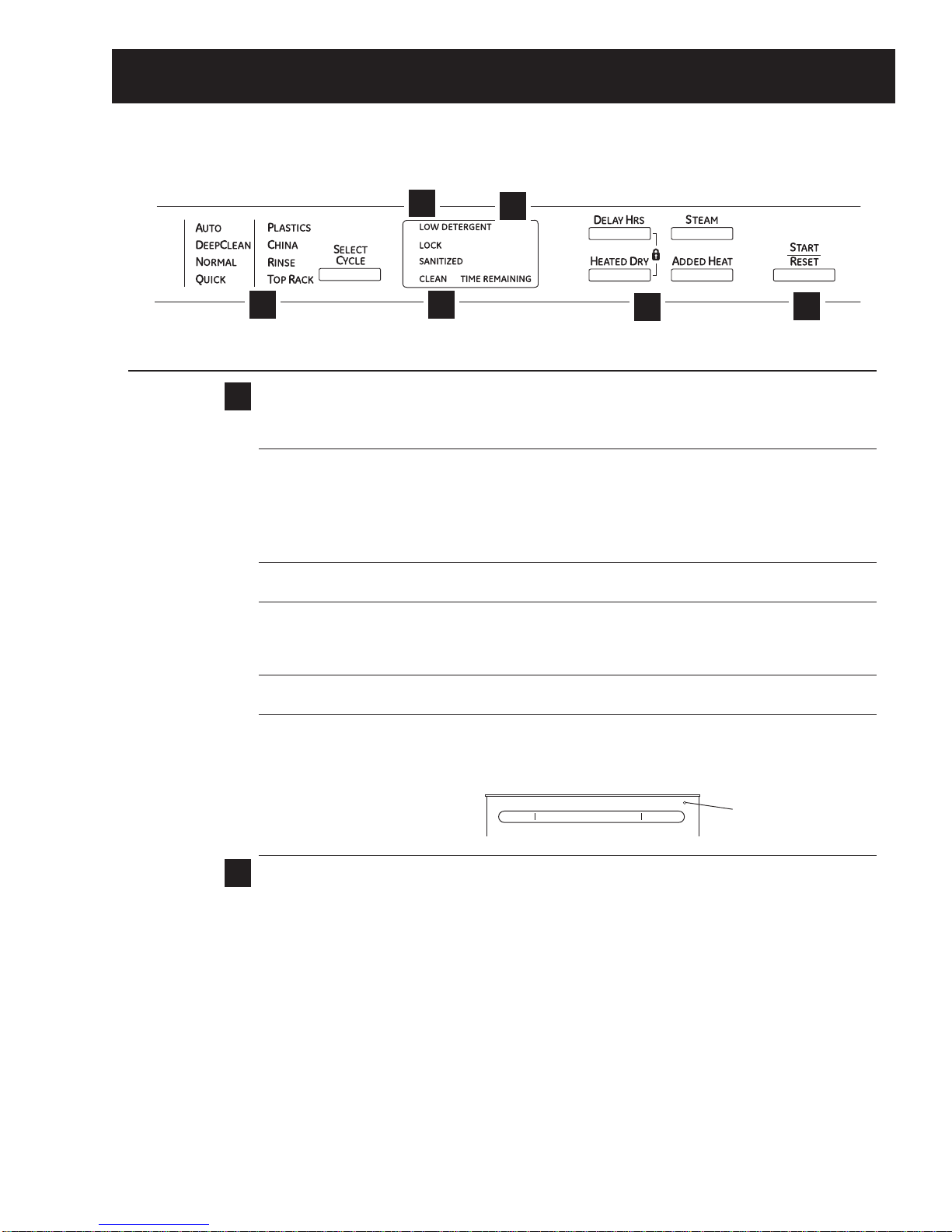
Control Features................................................................................................................................................................ 7
Control Thermal Cutout (TCO)......................................................................................................................................22
Consumer Purge of the Bulk Dispenser Tank......................................................................................................21
Cycle Chart..........................................................................................................................................................................12
Cycles.....................................................................................................................................................................................11
Detergent/Rinse Module................................................................................................................................................24
Dishwasher Components..............................................................................................................................................17
Door Handle........................................................................................................................................................................24
Door Switch Assembly...................................................................................................................................................24
Drain Pump Assembly....................................................................................................................................................35
Factory Test Mode............................................................................................................................................................39
Fill Funnel..............................................................................................................................................................................33
Fine Filter..............................................................................................................................................................................29
Float Switch.........................................................................................................................................................................31
Heating Element................................................................................................................................................................32
Inner Door Panel...............................................................................................................................................................26
Introduction......................................................................................................................................................................... 6
Lens.........................................................................................................................................................................................23
Lower Wash Arm..............................................................................................................................................................28
Motor Pump Assembly...................................................................................................................................................35
Nomenclature.................................................................................................................................................................... 5
Outer Door Panel..............................................................................................................................................................17
Schematics and Wiring Diagrams............................................................................................................................40
Service Mode......................................................................................................................................................................37
(Continued next page)

– 4 –
SmartDispenseTM...............................................................................................................................................................18
Sump Filter...........................................................................................................................................................................29
Tactile Switch......................................................................................................................................................................23
Troubleshooting ...............................................................................................................................................................37
Tub Gasket...........................................................................................................................................................................27
Tub Thermal Cutout (TCO).............................................................................................................................................36
Turbidity Sensor................................................................................................................................................................31
Upper Wash Arm..............................................................................................................................................................28
Vent Fan................................................................................................................................................................................25
Warranty..............................................................................................................................................................................41
Water Hardness Test and Calibration.....................................................................................................................17
Water Inlet Valve...............................................................................................................................................................33

– 5 –
Feature Pack
G D W T 6 6 8 V B B
Product Type
GDW = GE Long Door
PDW = Profile
CDW = GE Café
Exterior Color
BB = Black
CC = Bisque
SS = Stainless Steel
WW = White
Model Year Designator
Model Number
The nomenclature plate is located on
the left side of the tub wall, inside the
door jamb.
The mini-manual is located behind
the access panel.
Nomenclature
Nomenclature
Handle/Control Location
0 = Latch/Front Control
6 = Recessed/Top Control
8 = Towel Bar/Top Control
Door
8 = Stainless Door
Top Control
T = Top Control
Serial Number
The first two characters of the serial number
identify the month and year of manufacture.
Example: VV123456S = November, 2011
V- NOV
Z - DEC
A - JAN
B - FEB
F - MAR
G - APR
H - MAY
L - JUN
M - JUL
R - AUG
S - SEP
T - OCT
2011 - V
2010 - T
2009 - S
2008 - R
2007 - M
2006 - L
2005 - H
2004 - G
2003 - F
2002 - D
2001 - A
2000 - Z
The letter designating
the year repeats every
12 years.
Example:
V - 2011
V - 1999
V - 1987
Access Panel

– 6 –
New Features and Benefits
• Five-stage filtration with Piranha™ hard food disposer
• Dedicated silverware jets
• Steam PreWash
• Fan assist dry with heated option and ActiveVent
• Fifty-two dBA sound level
• ENERGY STAR® qualified and CEE Tier II rated
• SmartDispense™ (only on models GDWT7XX, PDWT3XX, PDWT5XX, CDWT980, and ZBD89XX)
Weights and Dimensions
Approximate Shipping Weight.........................................................................................................................................115 lb
Net Weight.................................................................................................................................................................................110 lb
Overall Height..........................................................................................................................................................................34 in.
Height with Legs Extended................................................................................................................................................35 in.
Overall Depth...........................................................................................................................................................................243/4in.
Overall Width............................................................................................................................................................................24 in.
Introduction

– 7 –
Throughout this manual, features and appearance may vary from your model.
Control Features
(Continued next page)
6
Control Settings
Status Indicator Lights (Indicators vary by models)
The Status display tells you what is happening while the dishwasher is in operation and may flash, indicating
a malfunction. The lights will come ON indicating the sequence of the dishwasher operation.
LOW DETERGENT Displayed when the SmartDispenseTM needs to be refilled with liquid or gel automatic
dishwasher detergent.
NOTE: If you are not using SmartDispenseTM and you want to turn the LOW DETERGENT
LED light off, press the ADDED HEAT button 5 times within 3 seconds. You will hear 3
beeps; then the light will go off. You can turn the light back on by pressing theADDED
HEAT button 5 times within 3 seconds.
SENSING Displayed while the Clean SensorTM is measuring the amount of soil and temperature
of water. The dishwasher will adjust the selected cycle to achieve optimal performance.
SANITIZED Displayed at the end of the cycle when SANITIZE has been selected and the dishwasher
has met the requirements for sanitization. See SANITIZE, below, for complete cycle
description. Opening the door or pressing any key while the door is closed and latched
will turn off the light.
CLEAN Displayed when a wash cycle is complete. Refer to Item 6, page 9, for further
explanation of clean light operation
CYCLE STATUS The cycle status indicator light is located on the right side of the dishwasher, above the
INDICATOR handle. This light comes on as amber while the selected cycle is running. The light turns
to green when the selected cycle is complete. The light stays ON as green as a reminder
that the dishes are clean until the door is opened or until another cycle is selected.
Time Remaining Display (on some models)
During operation, the display shows the minutes remaining until the cycle is complete. The display may
adjust the remaining time while the Sensing light is on. The time displayed at the start of each cycle may
change from the factory setting as the unit customizes itself to home use. During a delay start, the display
will show hours of time remaining until the cycle starts.
NOTE: This dishwasher is equipped with CleanSensorTM with automatic temperature control; therefore,
cycle length and time may vary depending on soil and water temperature conditions.
2
1
Top-Control Dishwashers
5
6
2
4
3
1
Cycle Status Indicator Light

– 8 – (Continued next page)

– 9 – (Continued next page)
The STEAM option will use the heater to
increase the temperature of the water. The circulation pump will turn off
periodicall , allowing water to drip onto the hot calrod which will create steam.

– 10 –
Start
5

– 11 –
Cycles
Auto Hot Start:
Auto Hot Start is initiated by the control board when it senses water temperature is below 80°F. If the water
is below 80°F after prewash, the unit circulates for 1 to 5 minutes (depending on the cycle selected) and then
drains for 75 seconds. This procedure repeats up to 4 times or until the water reaches 80°F.
Added Heat:
The added heat option differs for the various cycles. Some cycles will not be modified, some cycles will
increase the calrod time, and some cycles will get additional segments added (e.g., AUTO has 6 segments
without added heat and 9 segments with added heat).
Heated Dry:
During HEATED DRY, the heater cycles at a rate of 60 seconds on and 51 seconds off.
Cycle Explanations and Exceptions:
• Turbidity Response is used during the SANITIZED, NORMAL, and AUTO cycles only.
• Timed cycles can change depending on the water temperature. If the minimum temperature is not met,
an extended time is added until the temperature is met or the time expires.
• Partial Drain and Fill Algorithm is used during NORMAL and AUTO cycles only.
• Auto Hot Start may cause the first prewash to repeat up to 4 times.
• Disabling STEAM will shorten the cycle time.
• If STEAM is selected during NORMAL or AUTO cycles, turbidity response is ignored, and cycle defaults to
the heavy soil algorithm.
• HEATED DRY takes 34 minutes for the NORMAL cycle while the other cycles vary to as long as 60
minutes for PLASTICS. There is no HEATED DRY for the RINSE cycle.
• Drain Overlap is a short period when both the wash and drain pumps run simultaneously as the
circulation cycle ends and draining begins.
• Drain Pause is a short period between the circulation cycle ending and the drain starting.
• Extend Times enables both the circulation pump and heater to operate simultaneously.
Turbidity Response
The turbidity response is measured in DC volts. Four to 5 VDC registers light soil and a shorter wash cycle,
while 0 to 2 VDC registers heavy soil and a longer wash cycle. SANITIZED wash measures the turbidity
response during the third prewash cycle and adjusts the time based on these measurements. NORMAL wash
measures the turbidity response during the first prewash and the prewash before the main wash. If a clean
response is measured during the first prewash, the cycle advances directly to the main wash with no drain or
fill. If a clean response is measured during the prewash before the main wash, the control shortens the active
heater time.

– 12 –
NormalCycle PW1* PW2 PW3 PW4 PW5 MW** PR 1 PR2 FR Dry
Cool-
Down
Fan
Turb DOE [Vdc] 3.1 - 5.0 5.0 - -
Turb MIN [Vdc] 2.1 - 5.0 5.0 - -
Turb MED [Vdc] 2.1 - 5.0 5.0 - -
Turb MAX [Vdc] 1.0 - 0.1 0.1 - -
Time DOE [min] 5 - - 10 - -
Time MIN [min] 5 - - 10 - -
Time MED [min] 5 - - 10 - -
Time MAX [min] 1 - 3 10 - -
MW DOE Circulate Time [min] - - 30 -
MW DOE Heater Time [min] - - 28 -
MW MIN Circulate Time [min] - - 30 -
MW MIN Heater Time [min] - - 27 -
MW MED Circulate Time [min] - - 30 -
MW MED Heater Time [min] - - 27 -
MW MAX Circulate Time [min] - - 30 -
MW MAX Heater Time [min] - - 30 -
Pre-Rinse 1 (PR 1) [min] - - 7 -
Pre-Rinse 2 (PR 2) [min] - - -
Final Rinse (FR) [min] - - - 6
Heater On Time [min] 0 - 0 10 - y** 0 - 5
Dry Time (Total Time) w/ HD [min] - - - 34
HD - Initial ON Time [min[ - - - 4
HD - Pulse OFF Time [sec] - - - 105
HD - Pulse ON Time [sec] - - - 75
Dry Time (Total Time) w/o HD [min] - - - 0
Cool-Down Time [min] - - - 14
Fan Time w/ Heated Dry [min] - - - 48
W/ Out Heated Dry [min] - - - 14
Pause time (circ to drain) [sec] 0 - 15 0 - 15 0 - 15
Fill Time (low flow water valve) [sec] 62 - 16 62 - 21 62 - 23
Fill Time (high flow water valve) [sec] 46 - 13 46 - 15 46 - 17
Drain Time [sec] 7 - 75 10 - 75 11 - 105
Max Temp Limit [F] - - - 158 - 158 - - 158
Min Temp Limit [F] -----120 - -120
Extend Time [min] 0 - 0 0 - 5 0 - 5
Total Primitive [min] 6.15 - 4.52 11.20 - 31.25 8.22 - 8.13 34.00 14.00
31.60 13.13
Shortest Cycle [min] 67.63 36.60
Longest Cycle [min] 93.82
ART (Max) [min] 69.82
ART (Med) [min] 69.82
AH-MW [min] NA
HTD [min] 34.00
CD [min] 14.00
* IF on PW1 the turbidity is greater than the DOE response the cycle will skip the drain portion of PW1, completely skip PW3, PW4, and skip the fill into MW…effectively merging PW1 and MW circ
* IF on PW1 the turbidity is less than the DOE response but greater than the MIN response the cycle will skip PW3, PW4.
** Circulation and Heater ON times for Main Wash are determined by the turb valies in PW1
*** Detergent/Rinse Aid relay will be activated in FR
NOTE: ****PW2, PW5, PR2 intentionally left blank due to separating the added heat functionality into its own cycle definition table. See Norm_Auto+AH cycle table.***
Cycle Chart

– 13 –
Front View
Component Locator Views
Control Panel View
Insulation
Access Panel
(Continued next page)
Door Latch
Control Panel
Door Panel
Control Assembly

– 14 –
Interior View (Without Racks)
Detergent/Rinse Module Compartment View
Detergent/Rinse Module
Detergent Compartment
Compartment Lid
Rinse Agent Cap
Rinse Agent Outlet
(Continued next page)
Indicator Window
Vent

– 15 –
Interior View of Basin (With Racks Removed) Left Side View (Insulation Removed)
Bottom View (Looking Up)
Spray Arm
Heating Element
Fill Hose
Fill Funnel
Front
Back Drain Pump
Tub TCO
Coarse Filter
Float Dome
Fine Filter
Hub Nut
Door Spring
Sump
Water Valve
Motor Pump Assembly
Turbidity Sensor
Heater
Overfill Switch

– 16 –
Control Board Connector Locator View
J5
J7
J3
J2
J1
J5 - Active Vent
J7 - Keypad
J1 - Power Supply
J2 - Power Switching
J3 - Turbidity/Temperature Sensor

– 17 –
Dishwasher Components
Outer Door Panel
The outer door panel must be removed to access
the control board, detergent/rinse module, control
TCO, tactile switch, door switch, vent, and lens.
To remove the outer door panel:
1. Remove the two 1/4-in. hex-head screws from
the bottom of the front door panel (one on each
side).
3. Remove the single Phillips-head screw from the
control cover.
2. Remove the ten T-15 torx screws from the outer
door panel.
Caution: Carefully remove the outer door from the
inner door frame.
4. Disconnect the wire harness from the tactile
switch.
Disconnect
Water Hardness Test and Calibration
Test Water Hardness
The automatic liquid dishwasher detergent
dispenser (SmartDispenseTM) dispenses the optimum
amount of detergent to clean the dishes. The
amount of detergent introduced during each cycle
is based on the soil level of the dishes and the
hardness of the water. Therefore, the correct water
hardness setting is very important for both optimum
cleaning of dishes and detergent usage.
(Continued next page)

– 18 –
Prior to its first use, the dishwasher must be
calibrated for water hardness. This process requires
the use of a water hardness test strip (Part #
WD01X10295).
Test water hardness following the instructions on
the test strip package shown above.
The 4 light green stripes on the test strip change
color depending on the water hardness. The harder
the water, the more stripes change from green to
red.
Note: If all stripes remain green after the test, the
outcome is "0 RED." The value to be entered into the
dishwasher is "1."
Convert the test reading according to the table
below.
Water Hardness Test Strip Indication
Red Stripes on Strip Value to Enter into Dishwasher
01
12
23
34
45
Note: 1 grain per gallon = 17.1 parts per million.
To enter water hardness value (on some models):
Note: Dishwasher must be in standby mode. Press
the SELECT CYCLE button to activate the tactile
switch and illuminate the lights on the control panel.
1. Press the SELECT CYCLE and DELAY HRS
buttons simultaneously and hold for 3 seconds.
2. The current hardness setting is shown on the
TIME REMAINING display.
3. Enter the value from the test strip using the
STEAM button to increase the value or the
SELECT CYCLE button to decrease the value.
4. Press the START/RESET button to return the
dishwasher to normal operation. The last
displayed value is saved as the water hardness
value.
SmartDispenseTM
SmartDispense is a bulk liquid detergent dispenser
assembly consisting of the following components:
• Detergent Reservoir – Mounted within the inner
door panel.
• Detergent Level Sensor – Connected to a LOW
DETERGENT LED on the control panel.
• Positive Displacement Pump – Injects
the optimal amount of detergent into the
dishwasher during each cycle.
Detergent Reservoir
Note: The SmartDispense system can only be used
with liquid or gel automatic dishwasher detergent.
To access the reservoir, push down on the cap
covering the reservoir to engage the ratchet, then
turn it counterclockwise to open.
(Continued next page)

– 19 –
Position the door at a 30- to 45-degree angle. Fill
the reservoir with a liquid automatic dishwasher
detergent until the detergent reaches the threads
of the reservoir access. The dispenser tank holds
approximately 45 ounces of liquid dishwasher
detergent (about 1 to 2 months' supply).
Place the cap on the reservoir access threads, push
down, and then turn clockwise until the cap is tight.
To remove the detergent reservoir:
Note: Removing the reservoir access collar causes
structural damage to the collar. It must be replaced
with a new part (Part # WD35X10059).
Remove the outer door panel. (See Outer Door
Panel.) Insert a small, flat blade screwdriver into the
slot in the side of the retaining collar and push the
screwdriver handle counterclockwise while turning
the reservoir access collar counterclockwise a
quarter turn. Remove the retaining collar. Unplug the
tube from the reservoir outlet and disconnect the
sensor from the control module.
Detergent Level Sensor
The SmartDispense detergent level sensor consists
of a single-level detection continuity sensor and
includes the following components:
• A grommet seal
• A LOW DETERGENT LED indicator light
• A wire harness
When the detergent in the reservoir drops below
the continuity sensor, a signal is sent to the control
board, and the LOW DETERGENT LED indicator light
is turned on. The light indicates 3 to 7 wash cycles
are left before the detergent reservoir is completely
empty.
Note: The LOW DETERGENT LED may look like it
is illuminated when in fact it is not. An illuminated
indicator shines bright red.
Note: If the SmartDispense system is not being
used, the LOW DETERGENT light can be turned off
(or on) by pressing the ADDED HEATbutton 5 times
within 3 seconds. There are 3 audible beeps when
the light goes off.
The sensor is similar to the type used in several
automotive applications, such as the windshield
wiper fluid reservoir.
LOW DETERGENT
SmartDispense
S
ENSING
W
ASHING
D
RYING
S
ANITIZED
C
LEAN
Light will
turn on
when time
to refill
The control takes a reading of the detergent level at
power-up (when power is restored from an outage)
and each time the door is closed and latched.
The control outputs a pulsing 5-VDC analog signal
to the sensor and monitors the return voltage.
Changes in the quantity of detergent in the tank
change the amount of current drawn by the sensor.
Note: The dispenser tank comes as an assembly.
It includes the sensor with wire harness, gasket,
and retaining collar. The complete assembly part
number is WD35X10058.
(Continued next page)

– 20 –
The routing of the DC wiring from the tank is very
important. The 3 tape points on the tank keep the
DC wiring perpendicular to the AC harness wiring
running down across the front of the tank.
Tank
Sensor and Gasket
Tape Point
Tape Point
Tape Point
Note: The dispenser tank, sensor with wire harness,
and gasket are only available as a complete
assembly (Part # WD35X10058). They are shipped
with a new dispenser tank retaining collar.
Detergent Level Sensor Strip Circuit
BRN/YELLOW RED
DETERGENT
SENSOR
J4-3
J4-1
The dispenser pump operates on 120 VAC. During
each prewash cycle, the pump is energized for 5
seconds, dispensing 4 ml of detergent.
The electronic control uses two inputs to determine
the total amount of detergent dispensed during the
main wash cycle:
• Soil level determined by the turbidity sensor
• Water hardness as calibrated for the location
A water hardness selection mode permits the
calibration of the water hardness for the location
at installation. (See Water Hardness Test and
Calibration.)
To determine the amount of detergent to dispense
during the main wash, the electronic control uses
the following formula:
4 ml x Number of Prewashes
+ 25 ml + Additional Quantity for Hardness
The additional quantity is a predefined quantity
of detergent based on the water hardness level
programmed into the control.
Positive Displacement Pump
The SmartDispense positive displacement pump
consists of a continuous flexible tube running from
the detergent reservoir to the inner door detergent
outlet. The tube runs around the inside edge of the
pump housing. A 3-roller impeller fits tightly into
the center of the pump housing, with each of the
3 rollers squeezing the sidewall of the tube. As the
impeller is driven counterclockwise by the motor, it
squeezes out a predetermined amount of detergent
for each 1/3 revolution of the impeller.
Approximate Detergent Use
From
Detergent
Reservoir
To Detergent
Outlet
Pump
Housing
Impeller
(Continued next page)
123 4
133414957
2 35.4 43.4 51.4 59.4
3 37.8 45.8 53.8 61.8
4 40.2 48.2 56.2 64.2
5 42.6 50.6 58.6 66.6
Smart Dispense Bottle Duration
123 4
1 10.3 8.3 6.9 5.9
2 9.6 7.8 6.6 5.7
3 9.0 7.4 6.3 5.5
4 8.4 7.0 6.0 5.3
5 8.0 6.7 5.8 5.1
Dosage (ml)
Hardness
Soil Level
Hardness
Bottle Duration (wks)
Soil Level
Smart Dispense Dosage Amount
SmartDispense Dosage Amount
SmartDispense Bottle Duration
Other manuals for GDWT668V
1
This manual suits for next models
10
Table of contents
Other GE Dishwasher manuals