GE Monogram ZBD6400 Series How to use

C
C
PUB # 31-9087 12/01
MODEL SERIES:
ZBD6400
ZBD6500
ZBD6600
ZBD6700
ZBD6900
ZBD7000
ZBD7100
TECHNICAL SERVICE GUIDE
GE Consumer Home ServicesTraining
Monogram Dishwasher

IMPORTANT SAFETY NOTICE
The information in this service guide is intended for use by
individuals possessing adequate backgrounds of electrical,
electronic, and mechanical experience. Any attempt to repair a
major appliance may result in personal injury and property
damage. The manufacturer or seller cannot be responsible for the
interpretation of this information, nor can it assume any liability in
connection with its use.
WARNING
To avoid personal injury, disconnect power before servicing this
product. If electrical power is required for diagnosis or test
purposes, disconnect the power immediately after performing the
necessary checks.
RECONNECT ALL GROUNDING DEVICES
If grounding wires, screws, straps, clips, nuts, or washers used
to complete a path to ground are removed for service, they must
be returned to their original position and properly fastened.
!
GE Consumer Home Services Training
Technical Service Guide
Copyright © 2001
All rights reserved. This service guide may not be reproduced in whole or in part
in any form without written permission from the General Electric Company.

6000 & 7000 Series DISHWASHERS
PAGE 1
1.0 PRODUCT INFORMATION Page 2
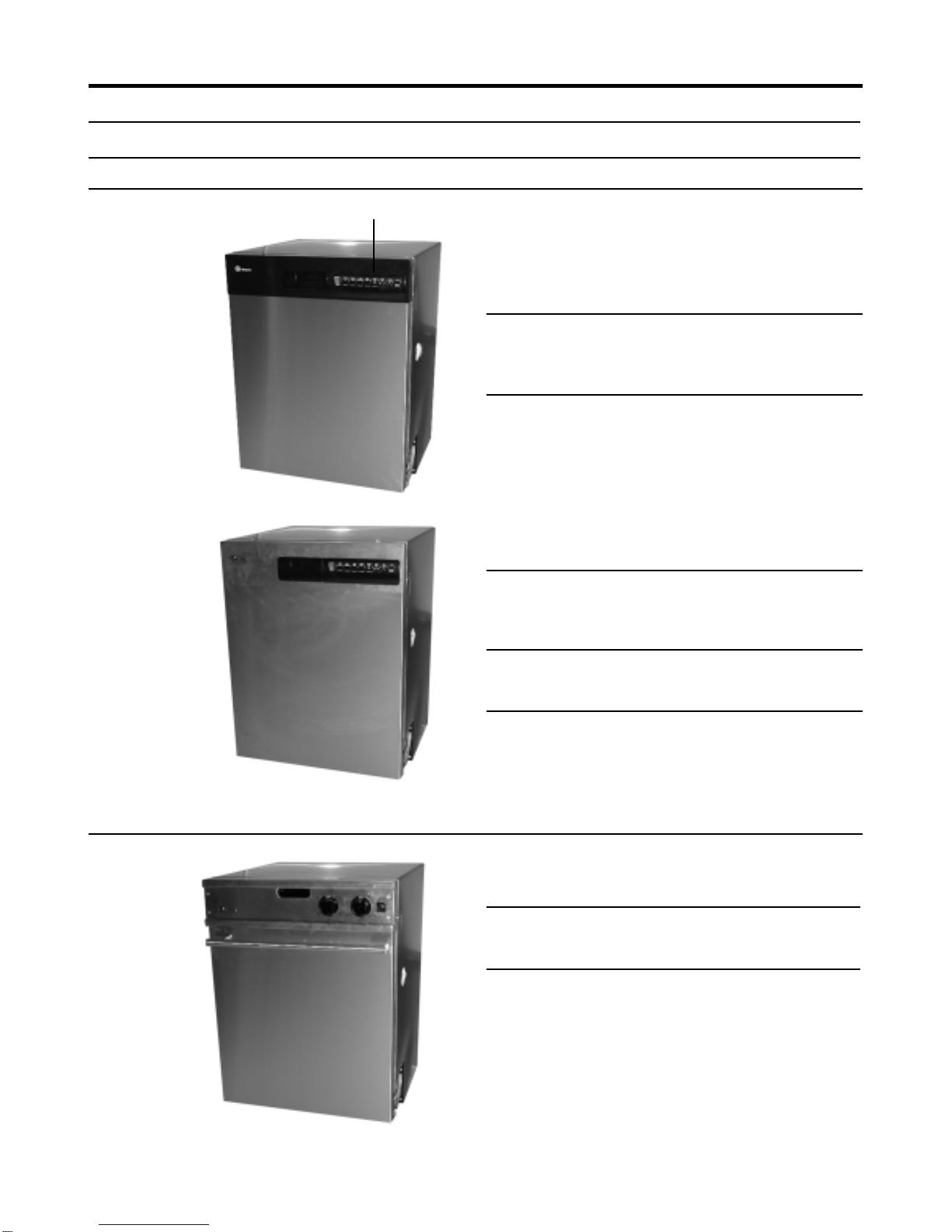
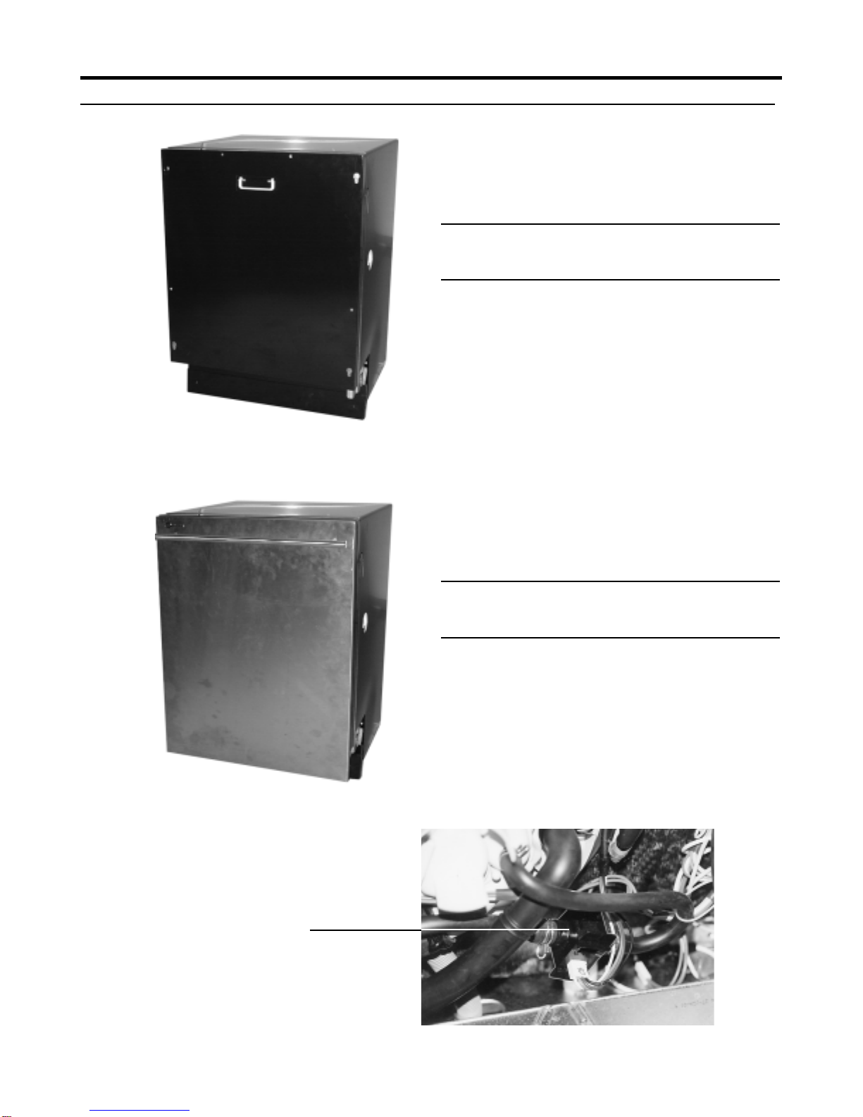
1.1 Description 2
1.2 Model Designation 4
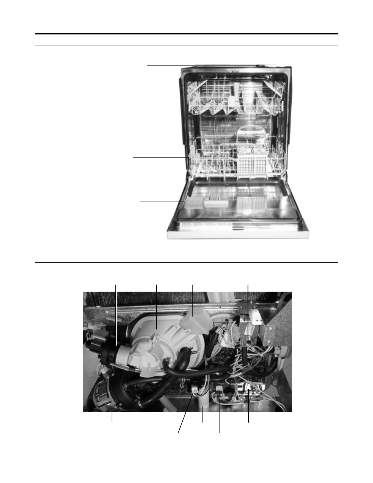
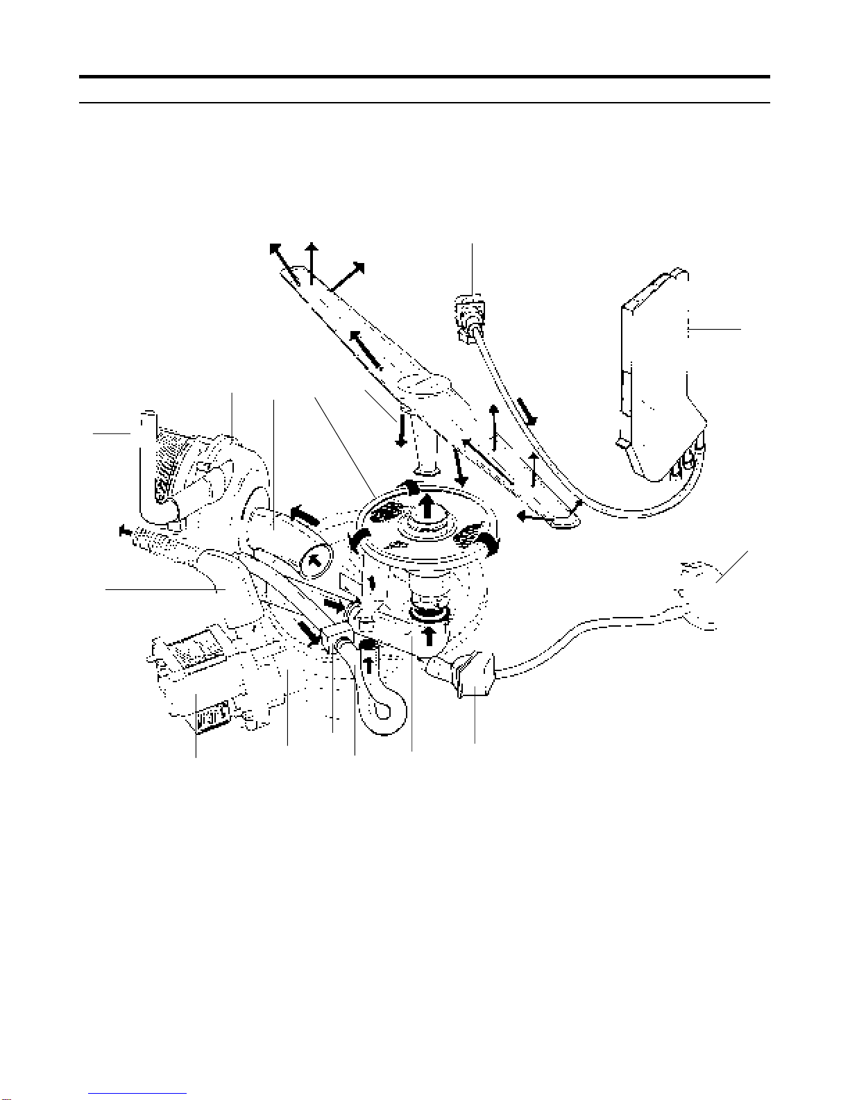
1.3 Major Component Location 6
1.4 Micro Filtration 7
2.0 SAFETY Page 9
2.1 Warning 9
2.2 Safety Practices 9
3.0 SPECIFICATIONS Page 10
3.1 General Specifications 10
4.0 FAULT DIAGNOSIS Page 14
4.1 Fault Indication Models 6400/6500, 6905, 7000 14
4.2 Fault Indication Models 6600, 6605 15
4.3 Not Heating 17
4.4 Over Temperature 17
4.5 Not Filling 17
4.6 Not draining 17
4.7 Overfill 17
4.8 Turbidity Sensor Failure 17
4.9 Door Thermistor Failure 17
4.10 Test Facilities 18
4.11 General Diagnostics 27
5.0 SERVICE PROCEDURES Page 32
5.1 General Access 32
5.2 Procedures 33
5.2.1 Door Latch 33
5.2.2 Door Panel 6400,6500,6600,6605 33
5.2.3 Door Panel 6700,6900,6905 33
5.2.4 Door Panel 7000,7005,7100,7105 34
5.2.5 Control Panel 6400, 6500, 6600, 6605 35
5.2.6 Power Control Panel 35
5.2.7 Control Panel 6400, 6500 37
5.2.8 Cabinet trims & Wrap Removal 38
5.2.9 Door Hinge, Spring & Support Rods 39
5.2.10 Stainless Steel Door Liner 39
5.2.11 Remove Door Hinges 40
5.2.12 Door Seal 40
5.2.13 Upper Venturi Assembly 41
5.2.14 Upper Venturi Assembly - Dismantle 42
5.2.15 Upper Venturi Assembly - Reassemble 42
5.2.16 Upper Venturi Assembly - Reinstall 42
5.2.17 Upper Basket Rail & Wheel Guides 42
5.2.18 Upper Basket Feed Pipe 43
5.2.19 Siphon Break 43
5.2.20 Drain Cup Filter 45
5.2.21 Perforated Stainless Steel LH side Wash Filter 45
5.2.22 Micro-mesh Barrel Wash Filter 45
5.2.23 Recuperative By-pass Filter 45
5.2.24 Lower Spray Arm Support 46
5.2.25 Perforated Stainless Steel RH side Wash Filter 46
5.2.26 General View beneath the Cabinet 47
5.2.27 Pressure Switch 48
INDEX
5.2.28 Capacitor - Wash Motor 48
5.2.29 Thermostat - Overtemperature 49
5.2.30 Heating Element 50
5.2.31 Turbidity Sensor 51
5.2.32 Air dome 51
5.2.33 Water Inlet Solenoid Valve 52
5.2.34 Drain Pump - Removal 52
5.2.35 Wash Motor Pump Assembly removal 53
5.2.36 Sump 56
5.2.37 Sump Base plate/Non-return Flap Valve 56
5.2.38 Interior Light 57
5.2.39 Detergent and Rinse Aid Dispenser 58
5.2.40 Drying Assist Fan 58
5.2.41 Door Handle 6400, 6500, 6700, 6900, 6905 59
5.2.42 Door Handle Cover Plate 6400, 6500, 6700,
6900, 6905 60
5.2.43 Door Lock Microswitch 6400, 6500, 6700,
6900, 6905, 6600, 6605 60
5.2.44 Door Lock Microswitch 7000, 7005,
7100, 7105 61
5.2.45 Door Lock Microswitch Lever 6400, 6500, 6700,
6900, 6905, 6600, 6605 61
6.0 PROGRAM & CIRCUIT INFORMATION
6.1.1 Programs - 6400 & 6500 Models 62
6.1.2 Programs - 6600 Rotary Model 63
6.1.3 Programs - 6605 Pots Rotary Model 64
6.1.4 Programs - 6700, 6900 & 7000 Models 66
6.1.5 Programs - 6905 Model 66
6.2 Circuit Diagram - Electronic Controller 67

6000 & 7000 Series DISHWASHERS
PAGE 2
1.0 PRODUCT INFORMATION
1.1 DESCRIPTION
1.1.1 Electronic Control Panel Models
Control Panel
Electronic Model 6400
All white door, cabinet, and control panel,
or all black door, cabinet, and control panel
Electronic Model 6500
Stainless steel door, black cabinet and control panel
1.1.2 Electronic Rotary Control Models
Electronic Rotary Model 6600
Stainless steel door and control panel, black cabinet,
Electronic Rotary Model 6605
Black cabinet, stainless steel door and control panel
No Turbity Sensor
Electronic Model 6700
All white door, control panel and cabinet,
or all black door, control panel and cabinet
Electronic Model 6900
Stainless steel door, black control panel and cabinet
Electronic Model 6905
Stainless steel door, black control panel and cabinet
No turbidity sensor

6000 & 7000 Series DISHWASHERS
PAGE 3
1.1.3 Electronic Integrated Models
Electronic Integrated Model 7000
Black cabinet, black door
Electronic Integrated Model 7005
Black cabinet, black door, no turbidity sensor
Electronic Integrated Model 7100
Black cabinet, stainless steel door
Electronic Integrated Model 7105
Black cabinet, stainless steel door, no turbidity sensor
Turbidity sensor

6000 & 7000 Series DISHWASHERS
PAGE 4
Detergent and
Rinse Aid
Dispenser
Lower Basket
Upper Basket
1.1.4 Interior, all Models
Light - All Models except 6400 & 6500
1.1.5 General view beneath the cabinet
Wash Motor / Pump Assembly Capacitor Heating Element
Turbidity Sensor (not on 6905, 6605) Overtemperature Thermostat
Drain Pump Sump Air Dome Water Inlet Solenoid Valve

6000 & 7000 Series DISHWASHERS
PAGE 5
1.2 Model Designation
Model 6400 6700 6905 6600 6605 7000 7005 7100 7105
6500 6900
Control Panel Type Electronic Electronic Electronic Electronic Electronic Electronic Electronic Electronic Electronic
Rotary Rotary Integrated Integrated Integrated Integrated
Door Finish
White 6400 6700 No No No No No No No
Black 6400 6700 No No No Yes Yes No No
Stainless 6500 6900 Yes Yes Yes No No Yes Yes
Programs
Rinse Only Yes Yes Yes Yes Yes Yes Yes Yes Yes
Speed Wash No No No Yes Yes No No No No
China Chrystal Yes Yes No Yes No Yes Yes Yes Yes
NormalWash YesYesNo YesNo YesYesYesYes
Pots&Pans YesYesNo YesNo YesYesYesYes
Pots Light No No Yes No Yes No No No No
Pots Normal No No Yes No Yes No No No No
Pots Heavy No No Yes No Yes No No No No
Options
Normal Temp Yes Yes Yes Yes Yes Yes Yes Yes Yes
Sani Temp Yes Yes Yes Yes Yes Yes Yes Yes Yes
Super Sani Temp No Yes Yes No No Yes Yes Yes Yes
Delay Start Yes Yes Yes No No Yes Yes Yes Yes
Heated Dry Yes No No Yes Yes No No No No
Smart Dry No Yes Yes No No Yes Yes Yes Yes
Clear Button Yes Yes Yes No No Yes Yes Yes Yes
Start/Clear Button No No No Yes Yes No No No No
Features
Fan Assisted Dry Yes Yes Yes Yes Yes Yes Yes Yes Yes
Turbidity Sensor Yes Yes No Yes No Yes No Yes No
Overfill Protection Yes Yes Yes Yes Yes Yes Yes Yes Yes
Interior Light No Yes Yes Yes Yes Yes Yes Yes Yes
Place Settings 10 10 10 10 10 10 10 10 10
Upper Basket
Height Adjustment Levels 222222222
Fold Down Cup Racks Yes Yes No Yes No Yes Yes Yes Yes
Fold Down Plate Racks No Yes No Yes No Yes Yes Yes Yes
Lower Basket
Fold Down Plate Racks Yes Yes No Yes No Yes No Yes Yes
Pots Wash Racks No No Yes No Yes No Yes No No
Cutlery Basket Covers Yes Yes No Yes No Yes No Yes Yes
Largest Plate (Inches) 12.2 12.2 12.2 12.2 12.2 12.2 12.2 12.2 12.2

6000 & 7000 Series DISHWASHERS
PAGE 6
1.3 Major Component Location
The diagram below illustrate the location of the major components. Refer to Section 5.1
1. Upper basket feed pipe
2. Drying assist fan
3. Door microswitch
4. Interior light (except 6400 & 6500)
5. Electronic controller
6. Siphon break
7. Light switch (except 6400 & 6500
8. Door hinge, spring and push rod guide
9. Pressure switch
10. Air dome
12 4
6
7
5
17
19
16
15
12
11. Water inlet solenoid valve
12. Turbidity sensor (except 6905, 6605, 7005 & 7105)
13. Sump
14. Drain pump
15. Overtemperature thermostat
16. Wash motor pump
17. Heating element
18. Wash motor capacitor
19. Detergent and rinse aid dispenser
20. Condensate duct
18
8
9
10
11
3
20
14 13

6000 & 7000 Series DISHWASHERS
PAGE 7
1.4 Micro-Filtration
1.4.1 Level 4 Micro-Filtration
These models have a 4 level micro-filtration stainless steel filtering system.
Level 1 -
Drain Cup Filter
Level 2 -
Perforated Stainless Steel Filters
Level 3 -
Micro-mesh Barrel Filter
Level 4 -
Recuperative By-pass Filter
Lower Spray Arm

6000 & 7000 Series DISHWASHERS
PAGE 8
1.4.2 Water flow - 4 Level System
The diagram below illustrates the water flow and identifies the main components in a 4 level micro-filtration system.
Note:The sump is drawn in dotted lines for illustration purposes.
1
10
10
2
3
4
8
9
1314
15
7
651112
1. Water solenoid inlet valve
2. Siphon break
3. Pressure switch
4. Air dome
5. Wash pump water inlet via sump
6. Wash pump
7. Wash pump water outlet to upper spray arm
8. Wash pump water outlet to lower spray arm
9. Wash pump water outlet to by-pass filter
10. Various lower spray arm water jets
11. Lower spray arm water jets to by-pass filter
12. Recuperative by-pass filter
13. Drain pump water inlet via sump
14. Drain pump
15. Water outlet to drain
16. Turbidity sensor
16

6000 & 7000 Series DISHWASHERS
PAGE 9
2.1WARNING
All work on electrical or plumbing systems must be carried
out by persons so qualified and in accordance with the
Federal, State or local authority legislation which applies.
Always ensure that the power supply box for the unit has
correct polarity and is within sight and reach of the unit being
serviced.
2.2 SAFETY PRACTICES
Ensure that the unit is ELECTRICALLY SAFE and there are
no WATER LEAKS before and after carrying out any service
work. When electrical power is required to be connected for
diagnosis or test purposes, disconnect the power immedi-
ately after use.
When carrying out tests on unit, ensure that high voltages do
not come into contact with low voltage circuit.
Do not operate unit with any panels removed other than the
kick panel and front panel.
At the beginning and/or end of each service procedure, the
appropriate icons below will appear as a reminder to
observe safe practices when servicing the unit.
Turn water supply off at main or isolating valve
.
Test for water leaks before leaving.
Switch off electrical power supply.
2.0 SAFETY
Reassemble dishwasher in reverse order.
Operate and test dishwasher before leaving.

6000 & 7000 Series DISHWASHERS
PAGE 10
3.1 GENERAL SPECIFICATIONS
3.1.1 Control System
All control and interface boards operate at 120v.
3.1.1.1 6400 & 6500 Models
The controller has eight surface mounted switches.
The control switches are:
Nine surface mounted green LED’s illuminate and display the
actual wash, water temperature, dry, and delay mode.
Five surface mounted green LED progress indicators illumi-
nate and display the actual wash mode as follows.:
SENSING WASHING RINSING DRYING CLEAN
All off board components are triac controlled, except the
wash motor relay and the heating element for heating and
drying which is also relay controlled.
3.1.1.2 6700 & 6900 Models
The controller has eight surface mounted switches.
The control switches are:
Ten surface mounted green LED’s illuminate and display the
actual wash, water temperature, dry, and delay mode.
Five surface mounted green led progress indicators illumi-
nate and display the actual wash mode as follows:
SENSING WASHING RINSING DRYING CLEAN
All off board components are triac controlled, except the
wash motor relay and the heating element for heating and
drying which is also relay controlled.
3.1.1.3 6905 Model
The controller has eight surface mounted switches.
The control switches are:
Ten surface mounted green LED’s illuminate and display the
actual wash, water temperature, dry, and delay mode.
Five surface mounted green LED progress indicators illumi-
nate and display the actual wash mode as follows:
SENSING WASHING RINSING DRYING CLEAN
All off board components are triac controlled, except the
wash motor relay and the heating element for heating and
drying which is also relay controlled.
3.0 SPECIFICATIONS
3.1.1.4 6600 Model
The controller has two large surface mounted rotary encod-
ers for wash cycles and heat options and a smaller surface
mounted switch for push button start.
The control switches are:
Two surface mounted red LED’s illuminate and display the
actual wash cycle and heat option selected.
All off board components are triac controlled, except the
wash motor relay and the heating element for heating and
drying which is also relay controlled.
3.1.1.5 6605 Model
The controller has two large surface mounted rotary encod-
ers for wash cycles and heat options and a smaller surface
mounted switch for push button start.
The control switches are:
Two surface mounted red LED’s illuminate and display the
actual wash cycle and heat option selected.
All off board components are triac controlled, except the
wash motor relay and the heating element for heating and
drying which is also relay controlled.
3.1.1.6 7000, 7005, 7100, & 7105 Models
The controller has eight surface mounted switches.
The control switches are:
Ten surface mounted green LED’s illuminate and display the
actual wash, water temperature, dry, and delay mode.
All off board components are triac controlled, except the
wash motor relay and the heating element for heating and
drying which is also relay controlled.

6000 & 7000 Series DISHWASHERS
PAGE 11
3.1.2 Water Circulating System
3.1.2.1 Wash Motor Capacitor
370V AC, 60Hz, 15µF.
Type - metallized Polypropylene.
Electrical connection - 2 x 1/4" x 1/32" Quick Connect tabs.
For usage 120V, 60Hz @ 185°F
3.1.2.2 Water Capacities
The Water Solenoid Inlet Valve is rated at a nominal 1.25 US
gallons per minute.The factory setting results in a nominal fill
of 1.17 to 1.95 US gallons subject to supply water pressure.
Water consumption: 6.0 US gallons (on fast wash)
Actual program selected will vary water consumption.
3.1.2.3 Solenoid Water Inlet 60Hz
Operating Supply Pressure Range:
- Static Cold: 20 psi minimum – 120 psi maximum
- Static Hot: 20 psi minimum – 120 psi maximum
Maximum inlet supply water temperature - 160°F
Nominal delivery flow rate from valve - 1.25 US gallons per
minute.
120V AC, 60Hz.
Solenoid DC resistance 750/950 ohms
Electrical connection - 2 x 1/4" x 1/32" Quick Connect tabs.
3.1.2.4 Drain Pump
Rated Input - 30W, 0.25A, 120V AC, 60Hz.
Resistance of Field Winding @ 68°F - 35 ohms ±10%.
Insulation - Class F.
Nominal RPM - 3000, 2 pole motor.
Motor temperature protector field winding - 338°F trips open.
Outlet Drain equipped with non-return flap valve.
Nominal Discharge Rate - 3.96 - 5.28 US gallons/minute @
3.25Ft/head.

6000 & 7000 Series DISHWASHERS
PAGE 12
3.1.2.5 Wash Motor/Pump Assembly
120V AC, 60Hz, 1.7A.
110W, MCR CS&R, 3250 rpm.
Class F
Capacitor 15µF 370V
WARNING: Motor is fitted with internal auto reset overload
and may restart without warning.
Resistance of windings @ 68°F ±5%
Terminals A & C = 11.6 ohms
Terminals B & C = 5.9 ohms
Motor Plug
3.1.3 Switches/thermostats
3.1.3.1 Thermostat - Overtemp
Identification - Blue Dot.
Mounting - Gasket in Tub base.
Electrical connection -1/4" Quick Connect tabs.
125V/250V.
Temperature specification: - Open 185°F ± 38°F.
- Reset 113°F ± 41°F.
3.1.3.2 Switch-Light
All Models except 6400 & 6500
240V/120V AC, 5A.
Circuit - normally Open.
Electrical connection - 2 x 1/4" Quick Connect tabs.
3.1.3.3 Microswitch - Door Lock
General Purpose Type approved by UL.
250/125V AC, 21A.
Pin Plunger Actuator SPST.
Normally open with common terminal at bottom.
Electrical connection - 1/4" Quick Connect tabs.
3.1.3.4 Pressure Switch - Level 1
Main Contact Load - 16A, 240/125V AC.
Electrical connection - 1/4" Quick Connect tabs.
Nominal Calibration - set 2 3/16" water
- reset 19/32" water
Operating Temperature - 185°F maximum.
UL Approved.
3.1.3.5 Pressure Switch - Level 2
Main Contact Load - 16A, 250/125V AC.
Electrical connection - 1/4" Quick Connect tabs.
Nominal Calibration - set 3 13/16" water
- reset 3 1/32" water
Operating Temperature - 185°F maximum.
UL Approved.

6000 & 7000 Series DISHWASHERS
PAGE 13
3.1.4 Miscellaneous
3.1.4.1 Detergent & Rinse Aid Dispenser
Single actuator type with gravity latch/lock mechanism.
110 - 240V AC, 60 Hz.
Total capacity of detergent chamber - 1.4 fl.oz.
Normal level detergent chamber - 0.9 fl.oz.
Total capacity Rinse Aid tank - 140cc (4.2 fl.oz).
Six Rinse Aid settings ranging from 4cc - 0.12 fl.oz.
3.1.4.2 Interior Lamp - All Models except 6400 & 6500
120V AC, 60 Hz
Lamp Globe - 120V, 15W (max) B15
Electrical Connections - 2 x 3/16" Quick Connect tabs.
Lamp Housing - 21/4" x 0.08" pitch buttress right hand
thread.
Ring gasket seal incorporated in lens.
Lens marked - maximum 15 watts.
3.1.4.3 Element - Heating
120V AC, 60 Hz, 1200W.
12 ohms 3 @ 68°F.
Insulation resistance - 1 meg ohms (minimum).
Element sheath material - 304 & 321 stainless steel.
Mounting - stainless steel (type 302)
Flange and stud - 1/4" stainless steel (type 302-304).
Ends of sheath sealed with epoxy-epirez 324A.
Electrical connection - 1/4" Quick Connect male stainless
steel (type 302-304) spade terminals.
3.1.4.4 Drying Assist Fan
Single phase 2 pole motor
120V 60Hz
Fan speed 2000rpm at free air
Coil:- wire dia. 0.132mm
No of turns 4000
DC resistance 292 ohms ± 10%
3.1.4.5 Turbidity sensor
All models except 6605, 6905, & 7105
Operating voltage 5V DC ± 5%
Output frequency 50Hz to 150 KHz
Operating temperature 50°F to 180°F
3.1.4.6 Dimensions
The diagram below illustrates the cupboard space required.

6000 & 7000 Series DISHWASHERS
PAGE 14
4.0 FAULT INDICATION
4.1 Models 6400/6500, 6700/6900, 6905, 7000 Series.
To assist with the diagnosis of dishwasher faults, any faults
that are detected during a wash cycle are saved in nonvola-
tile memory. These fault codes can then be accessed later on
during a service call.
4.1.1 Fault Identification methods for faults detected
during a wash cycle:
If a Not filling and/or Not draining fault is detected during a
wash cycle, then the respective fault codes are to be dis-
played when detected, and remain on if the door is opened.
If a Not Filling fault code is detected during a wash cycle, then
the China Crystal or Light Wash LED will flash, at a rate of 0.5
second on, 0.5 second off.
If a Not Draining fault code is detected during a wash cycle,
then the Rinse Only or Sani Wash LED will flash, at a rate of
0.5 second on, 0.5 second off.
These fault codes can only be cleared from the display by
pressing and holding the START/CANCEL button for 3 sec-
onds at the end of the wash cycle, or by starting a new wash
cycle.
(The fault codes stored in nonvolatile memory will not
be cleared).
4.1.2 Other Fault Identification methods:
Activating the Fault Indication mode:
If a fault has been detected by the Field Test Cycle, or by the
Factory Test Cycle, then the Fault Indication mode will be
automatically activated, and the fault will be reported as
indicated below.
To manually recall the saved fault codes, press the buttons in
the following sequence:
6400/6500 6700/6900
#5 Heated Dry #5 Smart Dry
#2 Normal Wash #2 Normal Wash
#4 Sani Wash #4 Rinse Only
#5 Heated Dry #5 Smart Dry
#6 Water Temp #6 Water Temp
6905 7000 Series
#5 Smart Dry #6 Smart Dry
#2 Normal Wash #2 Normal Wash
#4 Rinse Only #4 Rinse Only
#5 Smart Dry #6 Smart Dry
#6 Water Temp #5 Water Temp
Notes: The buzzer will then sound for 1 second to indicate
that the Fault Indication mode has been accessed. Note:
Buzzer silencing mode has no effect in this mode.
If no fault codes were saved, the control is to return to the
stand-by (off) state with no LEDs illuminated.

6000 & 7000 Series DISHWASHERS
PAGE 15
4.1.4 Exiting the Fault Indication mode:
To exit the fault indication mode, and clear any saved fault
codes from memory, press and hold down the START/
CANCEL button for 3 seconds. The control will then go into a
standby (off) state with all LEDs off.
Note:The Average Clean
Water Turbidity (ACWT) value will also be cleared.
To exit the fault indication mode, without clearing the saved
fault codes, repeat the button pressing sequence shown
above, or remove power.
4.2 Rotary Models 6600 and 6605.
To assist with the diagnosis of dishwasher faults, any faults
that are detected during a wash cycle are saved in nonvola-
tile memory. These fault codes can then be accessed later on
during a service call.
4.2.1 Fault Identification methods for faults detected
during a wash cycle:
If a Not filling and/or Not draining fault is detected during a
wash cycle, then the respective fault codes are to be dis-
played when detected, and remain on if the door is opened.
If a Not Filling fault code was detected during a wash cycle,
then the Wash Cycles indicator LED will flash, at a rate of 0.5
second on, 0.5 second off, .
If a Not Draining fault code was detected during a wash cycle,
then the Heat Options indicator LED will flash, at a rate of 0.5
second on, 0.5 second off.
These fault codes can only be cleared from the display by
pressing and holding the START/CANCEL button for 3 sec-
onds at the end of the wash cycle, or by starting a new wash
cycle.
(The fault codes stored in nonvolatile memory will not
be cleared).
4.2.2 Other Fault Identification methods:
Activating the Fault Indication mode:
If a fault has been detected by the Field Test Cycle, or by the
Factory Test Cycle, then the Fault Indication mode will be
automatically activated, and the fault will be reported as
indicated below.
To manually recall the saved fault codes, carry out the
following sequence:
1. Ensure the dishwasher is in Stand-by (OFF) with no
program LEDs on;
2. Align the WASH CYCLES and HEAT OPTIONS knobs
so that both knobs are horizontal with their position indicators
pointing away from each other;
3. Press and hold the Start/Cancel button for 3 seconds.
Notes:The buzzer will then sound for 1 second to indicate
that the Fault Indication mode has been accessed. Note:
Buzzer silencing mode has no effect in this mode.
If no fault codes were saved, the control is to return to the
stand-by (off) state with no LEDs illuminated.
4.1.3 Identifying any faults that may have occurred:
The fault codes (if any saved) are displayed by flashing the relevant LEDs, (at a rate of 0.5 second on, 0.5 second off, unless
otherwise noted). Refer table below.
Fault detected
Not Heating
Over Temperature
Door thermistor.
Not filling
Not draining
Overfill
Turbidity Sensor
High Signal
No Signal &
Low Signal
Turbidity Temp Sensor
Fault code LED
Normal Wash
Pots & Pans or Heavy Duty indicator LED will flash
at the standard rate (0.5 second on 0.5 second off).
Pots & Pans or Heavy Duty indicator LED will flash
slowly (1 second on, 1 second off).
China Crystal or Light Wash
Rinse Only or Sani Wash
Heated Dry or Smart Dry
Water Temp HIGH or SANI.
Delay Start 2hr
Delay Start 4hr
Condition
< 9 deg F in 15 minutes
Greater than 180ºF, (but less than 210°F).
Open circuit thermistor, (temperature sensed
is below 32°F) or short circuit thermistor,
(temperature sensed is above 210°F).
Not filled after selected fill time
Not drained in 5 minutes
Leak Detection switch closed or 2nd level
pressure switch
Count is greater than 65,279 in 0.4 seconds
Counter did not receive pulses from sensor
Count is less than 50 in 3 seconds
Thermistor shorted ,open or constant

6000 & 7000 Series DISHWASHERS
PAGE 16
4.2.5 HEAT OPTIONS
knob position.
6600 6605 Fault type to check for: Heat Options indicator LED will be
illuminated (fault detected) if:
Normal Normal
Open or short circuit
Temperature sensed was below 32°F
Door thermistor.
or above 210°F.
Normal & Normal &
Open or short circuit
Temperature sensed was below 32°F
Heat Dry. Heat Dry.
Door thermistor.
or above 210°F.
Turbidity Sensor
Sanitize. Sanitize.
High Signal
Count was greater than 65,279 in 0.4 seconds
High Temp. & High Temp. &
No Signal &
Counter did not receive pulses from sensor.
Heat Dry. Heat Dry.
Low Signal
Count was less than 50 in 3 seconds.
High Temp. High Temp.
Turbidity Temp Sensor
Thermistor was shorted ,open or constant.
4.2.6 Exiting the Fault Indication mode:
To exit the fault indication mode, and clear any saved fault
codes from memory, press and hold down the START/
CANCEL button for 3 seconds. The control will then go into a
stand-by (off) state with all LEDs off.
Note: The Average
Clean Water Turbidity (ACWT) value will also be cleared.
To exit the fault indication mode, without clearing the saved
fault codes: Remove power; or carry out the following se-
quence:
1. Align the WASH CYCLES and HEAT OPTIONS knobs
so that both knobs are horizontal with their position indicators
pointing away from each other;
2. Press and hold the Start/Cancel button for 3 seconds.
4.2.4 WASH CYCLES
knob position.
6600 6605 Fault type to check for: Wash Cycles indicator LED will be
illuminated (fault detected) if:
Normal Wash. Normal Wash.
Not Heating
< 9 °F in 15 minutes.
Pots & Pans Heavy Duty.
Over Temperature
Greater than 180ºF, (but less than 210°F).
China Crystal. Light Wash.
Not filling
Not filled after selected fill time.
Rinse Only. Rinse Only.
Not draining
Not drained in 5 minutes.
Speed Wash. Speed Wash.
Overfill
Leak Detection switch closed or
2nd level pressure switch activated.
4.2.3 Identifying any faults that may have occurred:
If a fault has been detected by the Field Test Cycle, or by the
Factory Test Cycle, and hence the Fault Indication mode has
been automatically activated, then the WASH CYCLES and
HEAT OPTIONS LEDs will alternate on and off once every
second, to indicate that a fault has occurred. This will
continue until the first fault is found, (the LEDs will then
behave in the manner specified below, and the Factory/Field
test fault indication buzzer will be silenced if it was still
activated).
To check if a particular fault has been recorded, rotate the
appropriate control knob to the corresponding Fault type to
be checked for. (Refer table below). If the selected fault type
has occurred, then the indicator LED above that knob will
flash, (at a rate of 0.5 second on, 0.5 second off), otherwise
the indicator LED will be off.
Note: As the two knobs operate independently of each
other, two faults can be identified at the same time.

6000 & 7000 Series DISHWASHERS
PAGE 17
with the previous values and this represents one period of
measurement.
There are 4 failure modes:
a. Low signal failure mode- the calibration routine ceases
and the dishwasher system invokes the default wash cycle.
This fault is non-correctable, does not have a fault suspected
mode and the Low signal fault flag is set
b. High signal failure mode - the same like above but the
High signal fault flag is set
Observation: a. & b. occurs when the calibration routine sets.
c. No signal failure mode - occurs when the turbidity sen-
sor outputs no pulses (if the receiver failed or a dishwasher
anomaly disrupts the signal from the receiver; if the LED
failed the receiver could continue to send pulses, less than
200 in the measurement interval)
During the calibration phase if the sensor output is less than
200 pulses in the maximum interval of 3 seconds, then the
Low signal fault is set. This condition is tested for each
turbidity measurement. If fault is suspected, then the routine
starts a counter, which will notify the fault detector when to
check the average count value again. The next check will be
after 4 samples of turbidity causing the detection period to
occur over 8 samples of turbidity. If the new average value is
again below the lower limit then the fault found flag is set and
the system notifies a No signal fault.
d. Turbidity temperature sensor failure mode – when the
control senses constant, abnormal voltages from turbidity
temperature sensor.This condition for sensor fault is checked
during each turbidity measurement.
This is a nonrecoverable fault the system invokes the default
wash cycle.
The following LEDs are used to indicate the faults:
Low signal failure mode - LED 2hr
High signal failure mode - LED High Temp.
No signal failure mode - LED 2hr.
Turbidity temperature sensor failure mode - LED 4hr.
4.9 DOOR THERMISTOR FAILURE
During the wash cycle when door temperature is monitored,
temperature sampling result is to be checked, in order to
identify if the door thermistor is faulty.
If the Temperature sensed is below 32°F, then an Open
Circuit Door Thermistor fault code is to be saved in memory
for fault diagnosis during service.
If the Temperature sensed is above 210°F, then an Short
Circuit Door Thermistor fault code is to be saved in memory
for fault diagnosis during service.
If a door thermistor fault is detected during a wash and heat
step of a cycle, then the heating element relay is to be de-
energized, and wash program operation is to continue until
the maximum time in that heating step has been reached, the
program is then to proceed to the next step.
4.3 NOT HEATING
During a heating cycle, if the water temperature sensed has
not been rising by greater than 9 deg F in 15 minutes, the
heating element relay is to be de-energized and wash
program operation is to continue until the maximum time in
that heating step has been reached, the program is then to
proceed to the next step. A not heating fault code is to be
saved in memory for fault diagnosis during service.
4.4 OVERTEMPERATURE
If at any time water temperature sensed exceeds 180º F,
program operation is to continue as normal, (without affecting
the wash program execution in any way), and an over-
temperature fault code is to be saved in non volatile memory
for fault diagnosis during service.
4.5 NOT FILLING
If the controller has not sensed that the pressure switch has
opened (water present) after the selected fill time, (refer
section 4.10.8 FILL LEVEL), (this is a prerequisite for pump
operation), the fill mode shall continue for a further 15
seconds or until the pressure switch opens, whichever occurs
first. If the pressure switch opens during the 15-second
period, the cycle shall continue, with total fill time remaining
as specified in the wash program.If the pressure switch does
not open after the additional 15 seconds, the control is to turn
off all outputs, indicate a not filling fault code to the user,
(refer section 4.1.3 IDENTIFYING FAULTS), and then save
the not filling fault code in non volatile memory.
4.6 NOT DRAINING
If the controller has not sensed that the machine is empty
after 5 minutes of draining, then the control is to turn off all
outputs, indicate a not draining fault code to the user, (refer
section 4.1.3 IDENTIFYING FAULTS), and then save the not
draining fault code in non volatile memory.
4.7 OVERFILL
Overfill detection is to have a 1-second steady state signal
before implementing.
The drain output is to be continuously monitored by the
control system. Whenever the drain output goes to active
potential other than in a normal drain cycle (i.e.. Leak Detec-
tion Switch or 2nd level pressure switch closed) the control is
to save in nonvolatile memory the overflow fault code and
continue the wash program.
4.8 TURBIDITY SENSOR FAILURE
A two-stage scheme is used for fault detection:
First stage – “fault suspected”: when a fault is first sensed, a
fault suspected flag is set
Second stage – “fault found”: if the fault is sensed again the
fault found flag is set
The second stage decides that the dishwasher system must
run the default wash cycle, but if the fault was not sensed for
a second time then the fault suspected flag is reset and the
fault has been corrected.
To increase the signal to noise ratio of the turbidity measure-
ment each turbidity value is an average of the current value

6000 & 7000 Series DISHWASHERS
PAGE 18
4.10 TEST FACILITIES
Several test functions are to be incorporated into the dishwasher control to facilitate fault finding.
Access to these test functions is via the normal front panel control switches.
Test functions incorporated are:
4.10.1 RELAY / TRIAC OUTPUTTEST
4.10.2 TEMPERATURE CALIBRATION TEST
4.10.3 WATER LEVEL SENSING OPERATION
4.10.4 TURBIDITY INPUT OPERATION
4.10.5 RINSE AID SWITCH INPUT OPERATION
4.10.6 FIELDTEST CYCLE
4.10.7 OVERFILLTEST
4.10.8 WATER FILL LEVEL
4.10.9 FAULT INDICATION
4.10.10 SPECIAL FUNCTIONS
Other manuals for Monogram ZBD6400 Series
3
This manual suits for next models
6
Table of contents
Other GE Dishwasher manuals

GE
GE GSD1350 User manual

GE
GE GDT550HGD0BB User manual

GE
GE GLDA696MSS User manual

GE
GE Monogram ZBD1870 User manual

GE
GE Profile Triton XL PDW7000 Series User manual

GE
GE Profile PDW8700N Manual

GE
GE EDW4000 Series User manual

GE
GE EDW4000 Series How to use

GE
GE Monogram ZBD8920PSS User manual

GE
GE Monogram ZBD7920PSS User guide