Installation Preparation-Electrical Supply
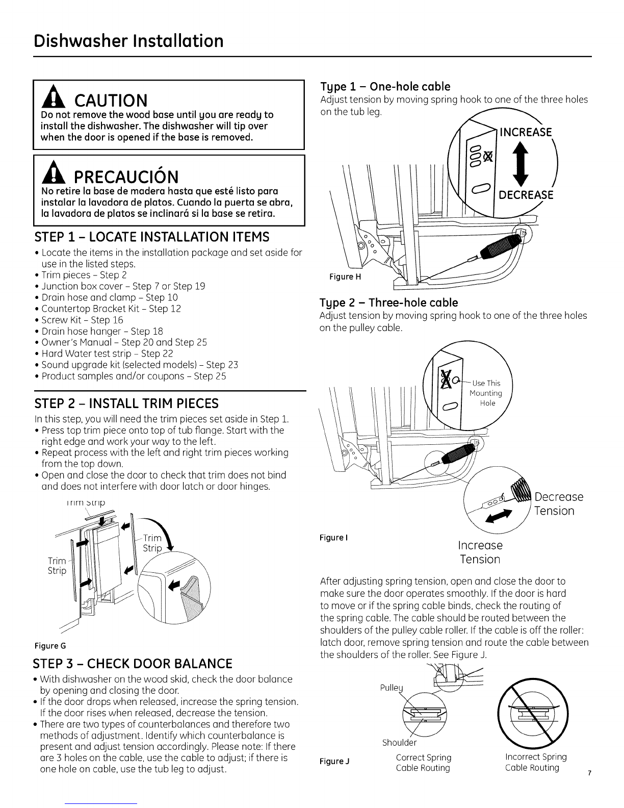
PREPARE ELECTRICAL WIRING
FOR PERSONALSAFETY:Remove house fuse
or open circuit breaker before beginning
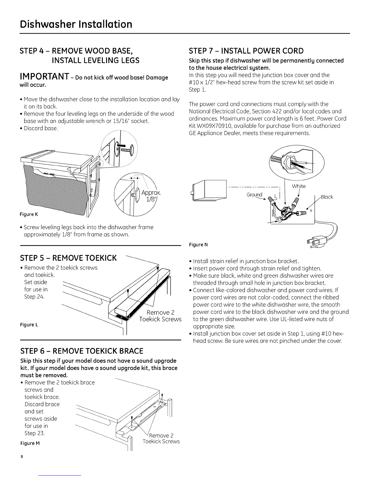
installation. Do not use an extension cord or
adapter plug with this appliance.
PARASEGURIDAD PERSONAL: Retire el
fusible de la casa o abra el interruptor de
circuitos antes de empezar la instalaci6n.
No use un cable de extensi6n o enchufe
adaptador con este aparato.
Electrical Requirements
• This appliance must be supplied with 120V,60Hz.,and
connected to an individual properly grounded branch circuit
protected by a 15- or 20-ampere circuit breaker or time-delay
fuse.
• Wiring must be 2 wire with ground and rated for 75°C (176°F).
• If the electrical supply does not meet the above requirements,
call a licensed electrician before proceeding.
Grounding Instructions-Permanent Connection
This appliance must be connected to a grounded-metal,
permanent wiring system, or an equipment-grounding
conductor must be run with the circuit conductors and be
connected to the equipment-grounding terminal or lead on
the appliance.
Grounding Instructions-Power Cord Models
This appliance must be grounded. Inthe event of a malfunction
or breakdown, grounding will reduce the risk of electric shock
by providing a path of least resistance for electric current.
This appliance isequipped with u cord having an equipment-
grounding conductor and a grounding plug. The plug must
be plugged into an appropriate outlet that is installed and
grounded in accordance with all local codes and ordinances.
The improper connection of the equipment
grounding conductor can result in a risk
of electric shock. Check with a qualified
electrician or service representative if gou
are in doubt that the appliance is properlg
grounded.
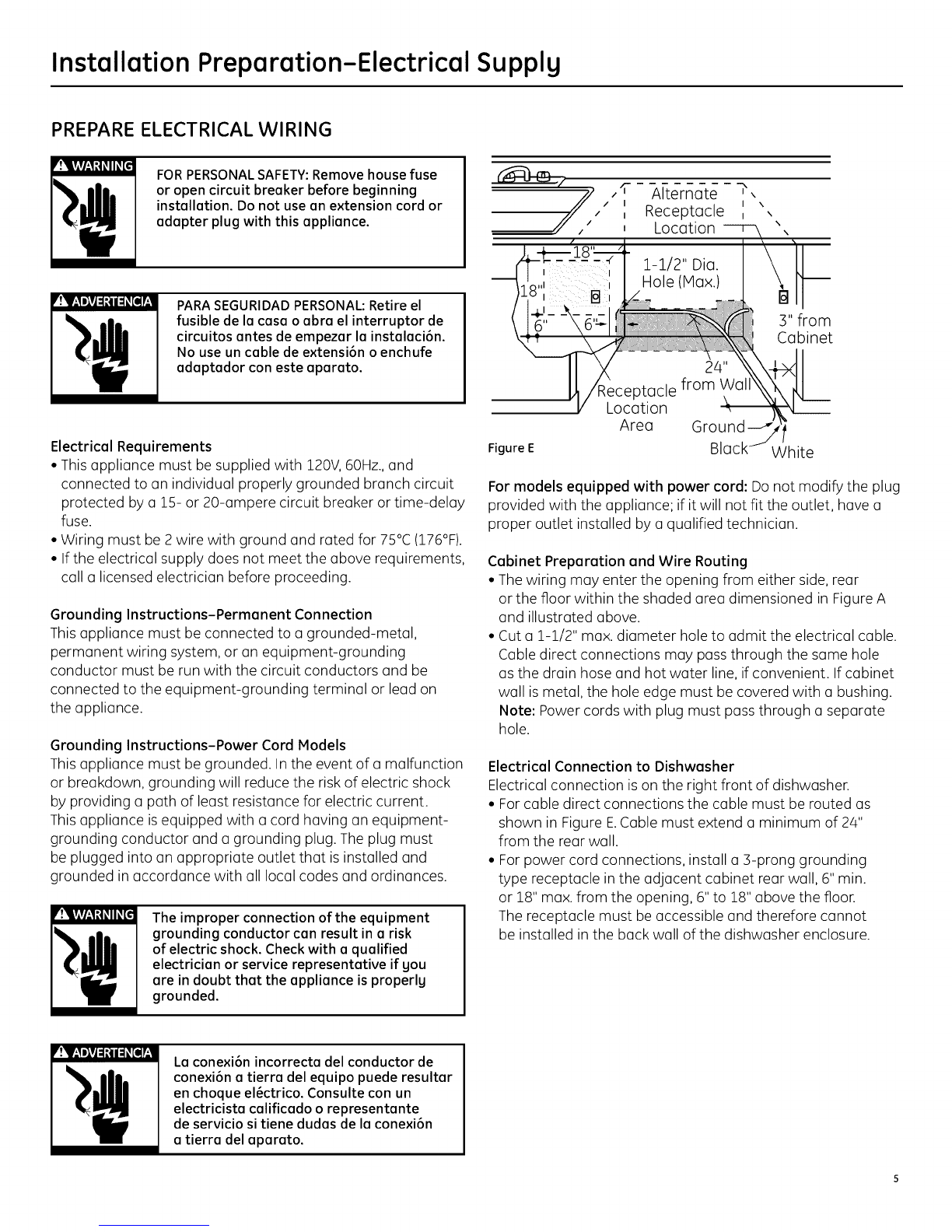
,'T Alternate ?
11 I \
• I \
," _ Receptacle
Location
1-1/2" Oio.
Hole(Max.)
3"from
Cabinet
Location
Area Ground
Figure E White
For models equipped with power cord: Do not modify the plug
provided with the appliance; if it will not fit the outlet, have a
proper outlet installed by a qualified technician.
Cabinet Preparation and Wire Routing
• The wiring may enter the opening from either side, rear
or the floor within the shaded area dimensioned in Figure A
and illustrated above.
• Cut o 1-1/2" max. diameter hole to admit the electrical cable.
Cable direct connections may pass through the some hole
as the drain hose and hot water line, if convenient. If cabinet
wall ismetal, the hole edge must be covered with o bushing.
Note: Power cords with plug must pass through o separate
hole.
Electrical Connection to Dishwasher
Electrical connection is on the right front of dishwasher.
• Forcable direct connections the cable must be routed as
shown in Figure E.Cable must extend a minimum of 24"
from the rear wall.
• Forpower cord connections, install a 3-prong grounding
type receptacle in the adjacent cabinet rear wall, 6" min.
or 18" max. from the opening, 6" to 18" above the floor.
The receptacle must be accessible and therefore cannot
be installed inthe back wall of the dishwasher enclosure.
Le conexi6n incorrecta del conductor de
conexi6n a tierre del equipo puede resultar
en choque el_ctrico. Consulte con un
electricista calificado o representante
de servicio si tiene dudas de le conexi6n
e tierre del epareto.